Deep Space Habitat Configurations Based On International ...
156
Deep Space Habitat Configurations Based On International Space Station Systems David Smitherman 1 and Tiffany Russell 2 NASA Marshall Space Flight Center, Huntsville, Alabama, 35812, USA and Mike Baysinger 3 , Pete Capizzo 4 , Leo Fabisinski 5 , Brand Griffin 6 , Linda Hornsby 7 , Dauphne Maples 8 , Janie Miernik 9 Jacobs Engineering, Science, and Technical Services Contract, Huntsville, Alabama, USA, 35806 A Deep Space Habitat (DSH) is the crew habitation module designed for long duration missions. Although humans have lived in space for many years, there has never been a habitat beyond low-Earth-orbit. As part of the Advanced Exploration Systems (AES) Habitation Project, a study was conducted to develop weightless habitat configurations using systems based on International Space Station (ISS) designs. Two mission sizes are described for a 4-crew 60-day mission, and a 4-crew 500-day mission using standard Node, Lab, and Multi-Purpose Logistics Module (MPLM) sized elements, and ISS derived habitation systems. These durations were selected to explore the lower and upper bound for the exploration missions under consideration including a range of excursions within the Earth- Moon vicinity, near earth asteroids, and Mars orbit. Current methods for sizing the mass and volume for habitats are based on mathematical models that assume the construction of a new single volume habitat. In contrast to that approach, this study explored the use of ISS designs based on existing hardware where available and construction of new hardware based on ISS designs where appropriate. Findings included a very robust design that could be reused if the DSH were assembled and based at the ISS and a transportation system were provided for its’ return after each mission. Mass estimates were found to be higher than mathematical models due primarily to the use of multiple ISS modules instead of one new large module, but the maturity of the designs using flight qualified systems have potential for improved cost, schedule, and risk benefits. 1 Study Lead, Advanced Concepts Office, MSFC/ED04, and AIAA Senior Member. 2 Environments, Advanced Concepts Office, MSFC/ED04, and AIAA Member. 3 Modeling, Advanced Concepts Office, MSFC/ED04, and AIAA Member. 4 Avionics, Advanced Concepts Office, MSFC/ED04, and AIAA Member. 5 Power, Advanced Concepts Office, MSFC/ED04, and AIAA Member. 6 Configurations, Advanced Concepts Office, MSFC/ED04, and AIAA Senior Member. 7 Thermal, Advanced Concepts Office, MSFC/ED04, and AIAA Member. 8 Mass Properties, Advanced Concepts Office, MSFC/ED04, and AIAA Member. 9 Structures and Environmental Controls, Advanced Concepts Office, MSFC/ED04, and AIAA Member.
Transcript of Deep Space Habitat Configurations Based On International ...
Deep Space Habitat Configurations Based On International Space Station Systems
David Smitherman1 and Tiffany Russell2 NASA Marshall Space Flight Center, Huntsville, Alabama, 35812, USA
and
Mike Baysinger3, Pete Capizzo4, Leo Fabisinski5, Brand Griffin6, Linda Hornsby7, Dauphne Maples8, Janie Miernik9 Jacobs Engineering, Science, and Technical Services Contract, Huntsville, Alabama, USA, 35806
A Deep Space Habitat (DSH) is the crew habitation module designed for long duration missions. Although humans have lived in space for many years, there has never been a habitat beyond low-Earth-orbit. As part of the Advanced Exploration Systems (AES) Habitation Project, a study was conducted to develop weightless habitat configurations using systems based on International Space Station (ISS) designs. Two mission sizes are described for a 4-crew 60-day mission, and a 4-crew 500-day mission using standard Node, Lab, and Multi-Purpose Logistics Module (MPLM) sized elements, and ISS derived habitation systems. These durations were selected to explore the lower and upper bound for the exploration missions under consideration including a range of excursions within the Earth-Moon vicinity, near earth asteroids, and Mars orbit. Current methods for sizing the mass and volume for habitats are based on mathematical models that assume the construction of a new single volume habitat. In contrast to that approach, this study explored the use of ISS designs based on existing hardware where available and construction of new hardware based on ISS designs where appropriate. Findings included a very robust design that could be reused if the DSH were assembled and based at the ISS and a transportation system were provided for its’ return after each mission. Mass estimates were found to be higher than mathematical models due primarily to the use of multiple ISS modules instead of one new large module, but the maturity of the designs using flight qualified systems have potential for improved cost, schedule, and risk benefits.
1 Study Lead, Advanced Concepts Office, MSFC/ED04, and AIAA Senior Member. 2 Environments, Advanced Concepts Office, MSFC/ED04, and AIAA Member. 3 Modeling, Advanced Concepts Office, MSFC/ED04, and AIAA Member. 4 Avionics, Advanced Concepts Office, MSFC/ED04, and AIAA Member. 5 Power, Advanced Concepts Office, MSFC/ED04, and AIAA Member. 6 Configurations, Advanced Concepts Office, MSFC/ED04, and AIAA Senior Member. 7 Thermal, Advanced Concepts Office, MSFC/ED04, and AIAA Member. 8 Mass Properties, Advanced Concepts Office, MSFC/ED04, and AIAA Member. 9 Structures and Environmental Controls, Advanced Concepts Office, MSFC/ED04, and AIAA Member.

1 MSFC/ED04 – DSH Configurations Based On ISS Systems FINAL 12-15-2011
David Smitherman / Space Systems Team
Advanced Concepts Office
December 15, 2011
Deep Space Habitat Configurations Based on International Space Station Systems
AES Habitation Project
(Update utilizing HAB and MPLM modules)
2 MSFC/ED04 – DSH Configurations Based On ISS Systems FINAL 12-15-2011
Space Systems Team
• Advanced Concepts Office
– Manager – Reggie Alexander
– Deputy Manager – Les Johnson
– Team Leads
• Space Systems – Jack Mulqueen
• Launch Systems – Ed Threet
• Jacobs Engineering Support – Tracie Bedsole
• Space Systems Team
– Study Lead – David Smitherman
– Configurations – Mike Baysinger
– Mass Properties – Dauphne Maples
– Crew Systems – Brand Griffin
– ECLSS – Janie Miernik
– Structures – Janie Miernik
– Propulsion – N/A
– Power – Leo Fabisinski
– Avionics – Pete Capizzo
– Thermal – Linda Hornsby
– Environmental Protection – Tiffany Russell
3 MSFC/ED04 – DSH Configurations Based On ISS Systems FINAL 12-15-2011
Study Plan Update
• Develop Deep Space Habitat (DSH) concepts based on International Space Station Systems
– Initial sizing range to include
• 4 crew / 60-Day mission
• 4 crew / 500-Day mission
• Investigate use of ISS HAB and MPLM sized modules
• Potential Benefits
– ISS hardware is flight qualified
– Mass may be higher but utilization could reduce overall project cost, schedule, and risk
– Incorporates ISS utilization into the program
– Offers an approach to incorporating International participation
• Include HAT requirements, ground rules & assumptions for the DSH
• Products
– General layouts, interior and exterior
– Mass properties
– Final documentation
HAT – Human Exploration Architecture Team
4 MSFC/ED04 – DSH Configurations Based On ISS Systems FINAL 12-15-2011
Ground Rules & Assumptions
Additional Assumptions
• Design intended to meet HAT missions with modifications as required to utilize current ISS and MPCV systems and technologies
• 60-Day Missions include
– EM L1 and EM L2 Missions
– GEO Satellite Servicing
– ES L2 Missions
– Lunar orbit Missions
– Microgravity Free-flyer
• 500-Day Missions include
– Some near-Earth asteroid missions
– Mars transit and orbital missions
• Sized for Existing Launch Vehicle Systems
– DSH can be broken down into smaller modular elements for EELV launch and/or outfitted at ISS
– SLS utilization not included but should be possible
• Assembled and serviced at ISS
• Propulsion and Control provided by CPS, MPCV, and/or SEP

5 MSFC/ED04 – DSH Configurations Based On ISS Systems FINAL 12-15-2011
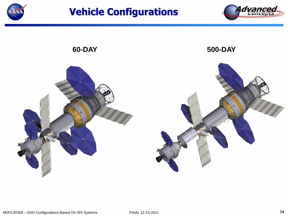
60 & 500-Day Vehicle Configurations
Basic Vehicle Elements
• Cryogenic Propulsion Stage (CPS) to be sized for mission
• HAB module (same size as ISS LAB module)
• Utility Tunnel / Airlock with attached FlexCraft or MMSEV
• Multi-Purpose Crew Vehicle (MPCV)
• Multi-Purpose Logistics Module (MPLM) added for 500-Day mission
60-Day Configuration
500-Day Configuration

6 MSFC/ED04 – DSH Configurations Based On ISS Systems FINAL 12-15-2011
Habitable Volume per Crew Based upon Average of Historical References
0
5
10
15
20
25
30
0 100 200 300 400 500 600
Ha
bit
ab
le V
olu
me
Pe
r C
rew
, m
3
Crewed Duration, days
Held constant at
365 day value
Draft – work in progress
Compiled by – NASA/LaRC/E402/Matt Simon with vehicle data added by ED04/David Smitherman
60-Day Habitat
Configuration
(65 m3)
500-Day Habitat
Configuration
(90 m3)
Stowage volume could be reduced
to increase habitable volume

7 MSFC/ED04 – DSH Configurations Based On ISS Systems FINAL 12-15-2011
Discipline Presentations
Configurations – Mike Baysinger
Mass Properties – Dauphne Maples
Crew Systems – Brand Griffin
ECLSS – Janie Miernik
Structures – Janie Miernik
Power – Leo Fabisinski
Avionics – Pete Capizzo
Thermal – Linda Hornsby
Environmental Protection – Tiffany Russell

8 MSFC/ED04 – DSH Configurations Based On ISS Systems FINAL 12-15-2011
Configuration
Mike Baysinger
December 15, 2011

9 MSFC/ED04 – DSH Configurations Based On ISS Systems FINAL 12-15-2011
Configurations
Docking ports
Radiators
11.5 m
HAB
Docking port
Tunnel
18 m
MPLM
HAB
Tunnel
60-DAY
500-DAY
4.5 m

10 MSFC/ED04 – DSH Configurations Based On ISS Systems FINAL 12-15-2011
60-Day Configuration
ECLSS and other subsystems
are located primarily above
ceiling and below floor
Crew Quarters (4)
Storage
Science Stations
Galley

11 MSFC/ED04 – DSH Configurations Based On ISS Systems FINAL 12-15-2011
500-Day Configuration
HAB
Tunnel /
Airlock
MPLM
500-day DSH:
Pressurized volume = ~ 193 m3
Habitable volume = ~ 90 m3
Stowage volume = ~ 49 m3
ECLSS
Service Tunnel / Airlock:
Pressurized volume = ~ 10 m3
Habitable volume = ~ 9 m3
Crew Quarters (4)
Storage
Science Stations
Galley
Storage
MPLM:
Pressurized volume = ~76 m3
Habitable volume = ~ 25 m3
Stowage volume = ~ 33 m3
HAB:
Pressurized volume = ~ 107 m3
Habitable volume = ~ 56 m3
Stowage volume = ~ 16 m3

12 MSFC/ED04 – DSH Configurations Based On ISS Systems FINAL 12-15-2011
500-Day Configuration
HAB Module MPLM
Tunnel / Airlock
ECLSS
(below floor)
Crew Quarters (4)
WMC
Science Stations
Galley
Opens up to Wardroom area
Storage
Storage in the MPLM includes 2
wall storage areas plus storage
areas in the floor and ceiling
Storage
Avionics and CHECS
Hatch
Habitat Plan View
Subsystems racks are
located primarily above
ceiling and below floor
Subsystems

13 MSFC/ED04 – DSH Configurations Based On ISS Systems FINAL 12-15-2011
Internal Secondary Structure
HAB shell
Secondary
Structure
Support
6 Equal Bays similar
to rack bay spacing
14 MSFC/ED04 – DSH Configurations Based On ISS Systems FINAL 12-15-2011
Vehicle Configurations
60-DAY 500-DAY
15 MSFC/ED04 – DSH Configurations Based On ISS Systems FINAL 12-15-2011
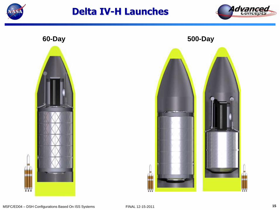
Delta IV-H Launches
60-Day 500-Day
16 MSFC/ED04 – DSH Configurations Based On ISS Systems FINAL 12-15-2011
Mass Summary
Dauphne Maples
December 15, 2011

17 MSFC/ED04 – DSH Configurations Based On ISS Systems FINAL 12-15-2011
Mass Summary: DSH MPLM Concept
Spacecraft Length: 11.5 m
Spacecraft Diameter: 4.5 m
60 Day Case 500 Day Case
Spacecraft Length: 18 m
Spacecraft Diameter: 4.5 m
Due to high TRLs, these designs may reduce cost, production, and flight-readiness schedule.
Average TRL: 7.7
TRL 9 Components: 43%
Average TRL: 7.7
TRL 9 Components: 43%
Dry Mass MGA: 12% Dry Mass MGA: 13.6%
Category Mass (kg)
Structures 14,116
Propulsion -
Power 924
Avionics 1,321
Thermal 2,868
Environment Protection 4,826
ECLSS 6,890
Crew Systems 807
EVA 272
Dry Mass 32,022
Stowed Provisions 2,766
Consumable Fluids 6,187
Non-Propellant Fluids 457
RCS Propellant -
DSH Wet Mass 41,430
Project Mgrs Reserve (PMR) (10%) 4,143
Total Wet Mass w/PMR 45,573
Category Mass (kg)
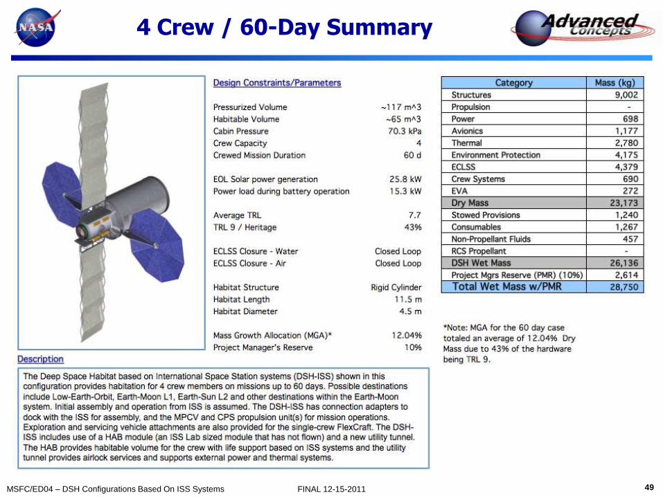
Structures 9,002
Propulsion -
Power 698
Avionics 1,177
Thermal 2,780
Environment Protection 4,175
ECLSS 4,379
Crew Systems 690
EVA 272
Dry Mass 23,173
Stowed Provisions 1,240
Consumables 1,267
Non-Propellant Fluids 457
RCS Propellant -
DSH Wet Mass 26,136
Project Mgrs Reserve (PMR) (10%) 2,614
Total Wet Mass w/PMR 28,750
18 MSFC/ED04 – DSH Configurations Based On ISS Systems FINAL 12-15-2011
GR&A / Reserves
• Ground Rules & Assumptions
– The Margin Growth Allocation (MGA) per component/subsystem will vary, depending on individual Technology Readiness Levels (TRLs)
– Project Manager’s Reserve will be 10% of the predicted mass/total wet mass
• Reserves
– Margin Growth Allocation
• MGA was applied to the basic mass of all subsystems included in Dry Mass
• Subsystem leads determined TRLs per component and applied MGA accordingly
– Project Manager’s Reserve
• PMR was applied to the total wet mass of the DSH
• 10% of the predicted mass (basic mass + MGA) for each category
− Includes DSH mass not considered Dry Mass, such as Stowed Provisions and Consumables

19 MSFC/ED04 – DSH Configurations Based On ISS Systems FINAL 12-15-2011
Crew Systems
Brand Griffin
December 15, 2011

20 MSFC/ED04 – DSH Configurations Based On ISS Systems FINAL 12-15-2011
Habitation and Autonomy 500-Days without resupply
Activity DSH Accommodation
Privacy, personal space Large crew quarters, no through traffic, quiet end of module, acoustic insulation, personal control over temperature/air flow, adjustable lighting, data/power access, private communications
Eating, group meetings Open area to accommodate all 4 crew, restraints for food and crew, one meal together per day
Food Preparation Open area, microwave, refrigerator
Sleeping Crew quarters, weightless restraints, change of bedding, radiation protection (storm shelter)
Exercise Open area, adjustable air flow, easily cleaned, scheduling should not conflict with common meal
Waste Mgt Larger enclosure than ISS, adjustable airflow, easily cleaned
Personal Hygiene Enclosed area for whole body cleansing, hand wash, brushing teeth, personal grooming
Recreation, off-duty time Crew choice, window, exercise, crew quarters or galley wardroom
Mission Operations Science and flight operation workstations
Autonomy DSH Accommodations
Servicing Easy access to ORUs and utilities. Service while operational.
Consumables Bring all consumables for entire mission (plus margin)
Spares Hot spares, stored spares, design for repair or work around
21 MSFC/ED04 – DSH Configurations Based On ISS Systems FINAL 12-15-2011
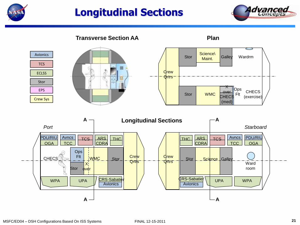
Longitudinal Sections
Avionics
TCS
ECLSS
Stor
EPS
Crew Sys
Longitudinal Sections Port Starboard
TCS THC ARS
CDRA OGA
Avionics
TCC
UPA WPA
Avncs
Crew
Qrtrs
CRS-Sabatier
PDU/RIU TCS PDU/RIU THC ARS
CDRA OGA
Avionics
TCC
UPA WPA
Avncs
Crew
Qrtrs
CRS-Sabatier
Galley Stor Ward
room
Science
Ops
Flt
Stor X
over
Stor WMC CHECS
Crew
Qrtrs
CHECS
(exercise)
Galley
WMC
Ops
Flt
Wardrm
X
over
Stor
CHECS
(med)
Stor
Science\
Maint.
Transverse Section AA Plan
A
A
A
A

22 MSFC/ED04 – DSH Configurations Based On ISS Systems FINAL 12-15-2011
Rack vs. Shell/ORU
Standoff (4)
Structure and Utilities
Rack rotates
to the center
ISSUE: Same size racks do not accommodate different functions
• Crew activities package differently than subsystems • Enclosures
• Multiple crew
• Subsystems have different access requirements • Single layer (don’t have to remove a component to get to another)
• Service while functioning
• Large aisle way • All rack swing against long axis
• Designed around infrequent operation
Deep
Compartment Open
Stow
Stow/
Subsystem
Equip
Pallet
Equip
Pallet
Easy access
utility packaging
(two sides)
Local Vertical
Open web
Longeron
Cable Tray (4)
Flex lines allow racks to
rotate and remain operational
ISS Rack Based Layout Shell/ORU Based Layout
Designed for ORU level Interchangeability Two-sided equipment pallet
Crew activities in wall
Subsystem to ceiling/floor
Dedicated utility interface
Local vertical for crew Head-to-toe air flow
Overhead lighting
Easy access Cable Tray
23 MSFC/ED04 – DSH Configurations Based On ISS Systems FINAL 12-15-2011
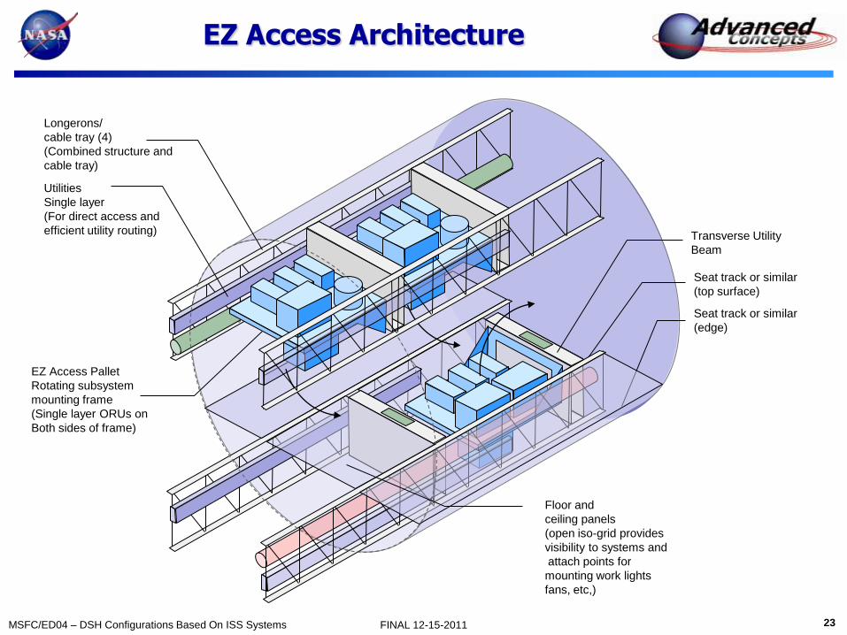
EZ Access Architecture
Longerons/
cable tray (4)
(Combined structure and
cable tray)
Utilities
Single layer
(For direct access and
efficient utility routing)
EZ Access Pallet
Rotating subsystem
mounting frame
(Single layer ORUs on
Both sides of frame)
Transverse Utility
Beam
Seat track or similar
(top surface)
Seat track or similar
(edge)
Floor and
ceiling panels
(open iso-grid provides
visibility to systems and
attach points for
mounting work lights
fans, etc,)

24 MSFC/ED04 – DSH Configurations Based On ISS Systems FINAL 12-15-2011
Utility Layout Comparison
X Over
Racks
Ceiling Floor Wall Wall
Utilities
End X-Over
• Long utility runs
• Larger dia ducts
• Noise
Standoff Lighting
• Two sides
• Easily obscured
•Standoff Air Supply
• Two sides
• Easily obscured
X Over
Ceiling Floor Wall Wall
Utilities
ISS Rack Based Shell/ORU Based
Middle X-Over
• Short utility runs
• Smaller dia ducts
• Less Noise
• More usable length
Central Lighting
• One light
• Good illumination
•Central Air Supply
• One diffuser
• Good distribution
Standoff Standoff Standoff Standoff Cable Tray Cable Tray Cable Tray Cable Tray
No Utilities Transverse
Utilities

25 MSFC/ED04 – DSH Configurations Based On ISS Systems FINAL 12-15-2011
Crew Quarters
Radiation
Protection
Crew Quarters (4)
DSH (~ 4 m3 each) ISS (~2 m3 each)
26 MSFC/ED04 – DSH Configurations Based On ISS Systems FINAL 12-15-2011
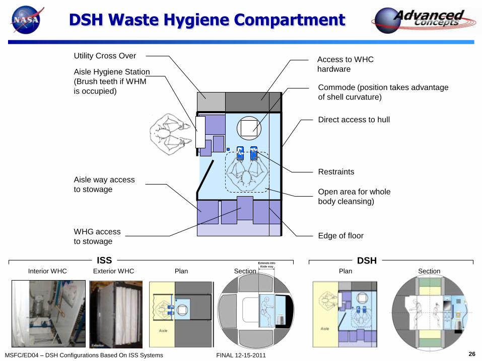
DSH Waste Hygiene Compartment
Utility Cross Over
Aisle Hygiene Station
(Brush teeth if WHM
is occupied)
Access to WHC
hardware
Commode (position takes advantage
of shell curvature)
Direct access to hull
Restraints
Open area for whole
body cleansing)
Aisle way access
to stowage
WHG access
to stowage Edge of floor
ISS DSH Interior WHC Exterior WHC Plan Plan Section Section

27 MSFC/ED04 – DSH Configurations Based On ISS Systems FINAL 12-15-2011
Accessibility Zoning
No immediate
access to hull
Zone Access
A Immediate Physical & Visual
B Indirect
C Infrequent
• No access
behind standoff
• Utilities enclosed
“compartment” depth
less than aisle width
ISS Stowage
ISS Access Shell/ORU

28 MSFC/ED04 – DSH Configurations Based On ISS Systems FINAL 12-15-2011
Stowage Concepts
Front Access Center Hinged Access Refrigerator Door
Side Hinged Access
Combo Combined Refrigerator
and Hinged Access
Combo (upper wedge access)
Combo (two quadrant and hull access)
29 MSFC/ED04 – DSH Configurations Based On ISS Systems FINAL 12-15-2011
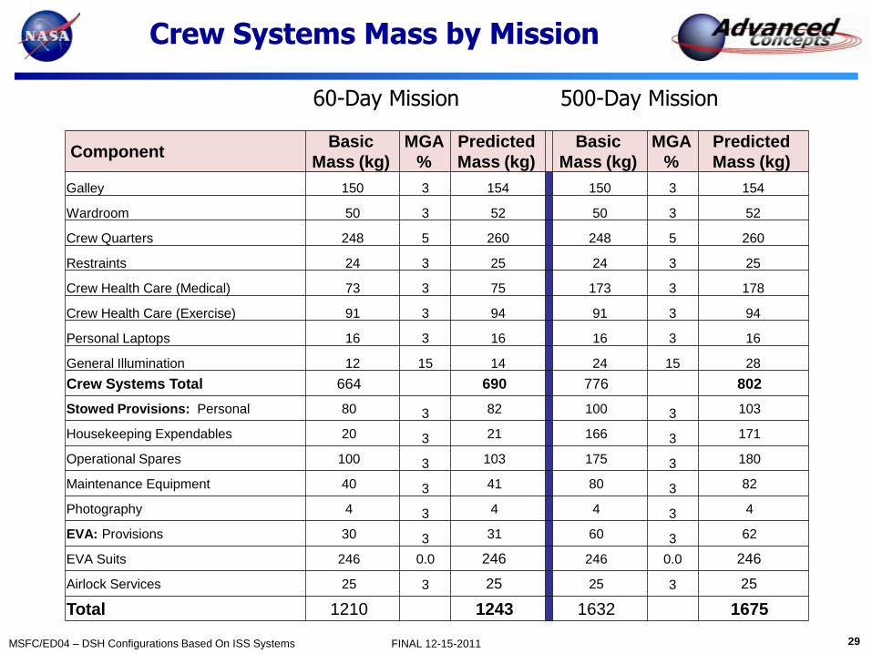
Crew Systems Mass by Mission
60-Day Mission 500-Day Mission
Component Basic
Mass (kg)
MGA
%
Predicted
Mass (kg)
Basic
Mass (kg)
MGA
%
Predicted
Mass (kg)
Galley 150 3 154 150 3 154
Wardroom 50 3 52 50 3 52
Crew Quarters 248 5 260 248 5 260
Restraints 24 3 25 24 3 25
Crew Health Care (Medical) 73 3 75 173 3 178
Crew Health Care (Exercise) 91 3 94 91 3 94
Personal Laptops 16 3 16 16 3 16
General Illumination 12 15 14 24 15 28
Crew Systems Total 664 690 776 802
Stowed Provisions: Personal 80 3 82 100 3 103
Housekeeping Expendables 20 3 21 166 3 171
Operational Spares 100 3 103 175 3 180
Maintenance Equipment 40 3 41 80 3 82
Photography 4 3 4 4 3 4
EVA: Provisions 30 3 31 60 3 62
EVA Suits 246 0.0 246 246 0.0 246
Airlock Services 25 3 25 25 3 25
Total 1210 1243 1632 1675

30 MSFC/ED04 – DSH Configurations Based On ISS Systems FINAL 12-15-2011
ECLSS Summary
Janie Miernik
December 15, 2011
31 MSFC/ED04 – DSH Configurations Based On ISS Systems FINAL 12-15-2011
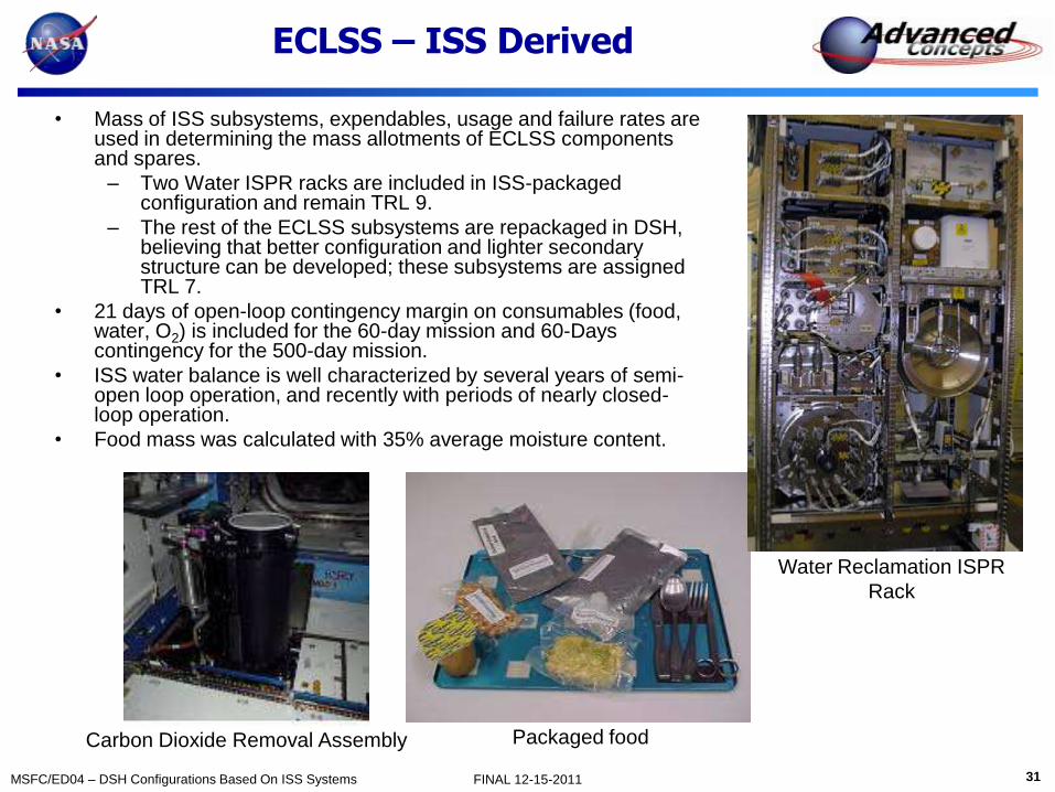
ECLSS – ISS Derived
• Mass of ISS subsystems, expendables, usage and failure rates are used in determining the mass allotments of ECLSS components and spares.
– Two Water ISPR racks are included in ISS-packaged configuration and remain TRL 9.
– The rest of the ECLSS subsystems are repackaged in DSH, believing that better configuration and lighter secondary structure can be developed; these subsystems are assigned TRL 7.
• 21 days of open-loop contingency margin on consumables (food, water, O2) is included for the 60-day mission and 60-Days contingency for the 500-day mission.
• ISS water balance is well characterized by several years of semi-open loop operation, and recently with periods of nearly closed-loop operation.
• Food mass was calculated with 35% average moisture content.
Carbon Dioxide Removal Assembly
Water Reclamation ISPR
Rack
Packaged food

32 MSFC/ED04 – DSH Configurations Based On ISS Systems FINAL 12-15-2011
Comparison of Mission/Mass
60-Day Mission 500-Day Mission
ECLSS Subsystem Basic Mass
(kg)
MGA
%
Predicted
Mass (kg)
Basic Mass
(kg)
MGA
%
Predicted
Mass (kg)
Atmosphere Revitalization Sys (ARS) 337 20 404 562 20 674
Atmosphere Cont & Supply System (ACSS) 400 20 480 1200 20 1440
Temp & Humidity Control (THC) 149 20 179 149 20 179
Waste Hygiene Compartment (WHC) 455 20 546.00 455 20 546
Water Recovery & Man (WRM) 1300 3 1339 1300 3 1314
Atmosphere Regen (OGA/ CO2 Red Assy) 1000 20 1200 1600 20 1860
Fire Detection & Suppression /module 35 30 46 70 30 91
Potable Water Tanks 180 3 185 680 3 700
ECLSS Hardware Total 3856 4379 6016 6890
ECLSS Expendables 200 3 206 500 3 515
ECLSS Spares 730 3 752 1600 3 1648
H2O 634 3 653 2520 3 2596
Food, packaged 337 10 371 2403 10 2643
Atmosphere Regen (O2) 114 3 117 670 3 690
Atmosphere Regen (N2) leakage 122 3 126 250 3 258
Total 5993 6603 13959 15239

33 MSFC/ED04 – DSH Configurations Based On ISS Systems FINAL 12-15-2011
Structures
Janie Miernik
December 15, 2011

34 MSFC/ED04 – DSH Configurations Based On ISS Systems FINAL 12-15-2011
Structures: ISS-Derived
• ISS STA Lab/HAB Module has known mass and is fabricated, not qualified, so is TRL 8.
• MPLM design is used but additional CBM docking port added, TRL drops to 7.
• The interior secondary structure is conservatively estimated at 20% of the mass that must be supported
and is assigned TRL 8.
• The tunnel/contingency airlock structure mass is based on ISS airlock areal mass, is assumed to be
fabricated in a similar manner, and is assigned TRL 7. External secondary structure for radiators, meteor
debris shielding and power systems are estimated at 20% of the mass to be supported.
• All ports will be CBM-sized and use ISS mass for these components. A NASA Docking System (NDS)
adapter will be used for MPCV interface; mass found in NDS documentation.
Multi-Purpose Logistics Module (MPLM)
STA Hab/Lab
MPLM Tunnel ISPR
Length 8.5 m (27.4 m)
6.5m (19 ft)
3.2 m (10.5 ft)
Height 2 m (6.1 ft)
Cylindrical section length
7.2 m (25.6 ft)
4.9 m (15 ft)
3.2 m (10.5 ft)
Width 1.05 m (3.4 ft)
Diameter 4.3 m (14 ft)
4.3 m (14 ft)
2.5 m (7.6 ft)
Max. depth
.86 m (2.8 ft)
Pressurized volume
107 m3
76.4 m3 10 m3 Volume 1.57 m3
Mass of shell incl. CBMs and hatches
3833 kg (8450 lbs)
2502 kg (5516 lbs)
1284 kg (2204 lbs) ~25 kg/m2
areal mass
Mass of 6-post rack
105 kg (230 lbs)
• A new launch adapter
must be developed for EELV
launch to interface ISS
elements and it is not
included in stated mass.
35 MSFC/ED04 – DSH Configurations Based On ISS Systems FINAL 12-15-2011
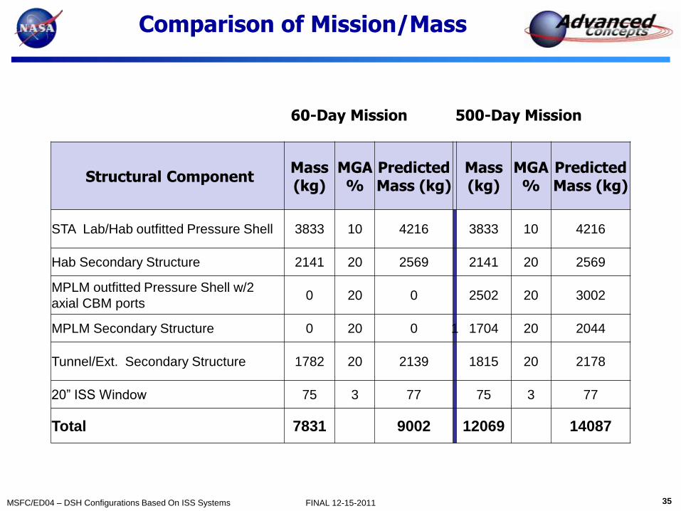
Comparison of Mission/Mass
60-Day Mission 500-Day Mission
Structural Component Mass (kg)
MGA %
Predicted Mass (kg)
Mass (kg)
MGA %
Predicted Mass (kg)
STA Lab/Hab outfitted Pressure Shell 3833 10 4216 3833 10 4216
Hab Secondary Structure 2141 20 2569 2141 20 2569
MPLM outfitted Pressure Shell w/2
axial CBM ports 0 20 0 2502 20 3002
MPLM Secondary Structure 0 20 0 1 1704 20 2044
Tunnel/Ext. Secondary Structure 1782 20 2139 1815 20 2178
20” ISS Window 75 3 77 75 3 77
Total 7831 9002 12069 14087
36 MSFC/ED04 – DSH Configurations Based On ISS Systems FINAL 12-15-2011
Power System
Leo L. Fabisinski
December 15, 2011

37 MSFC/ED04 – DSH Configurations Based On ISS Systems FINAL 12-15-2011
Power System Summary
• Power Requirement:
– 60-Day : 14,136 W
– 500-Day: 18, 824 W
• UltraFlex Arrays with
Inverted Metamorphic
(IMM) Cells
• 120V MPCV-Compatible Bus
• VME Power Electronics Boards
(MPCV Heritage)
• Off-The-Shelf VME Enclosure
for Power Electronics
38 MSFC/ED04 – DSH Configurations Based On ISS Systems FINAL 12-15-2011
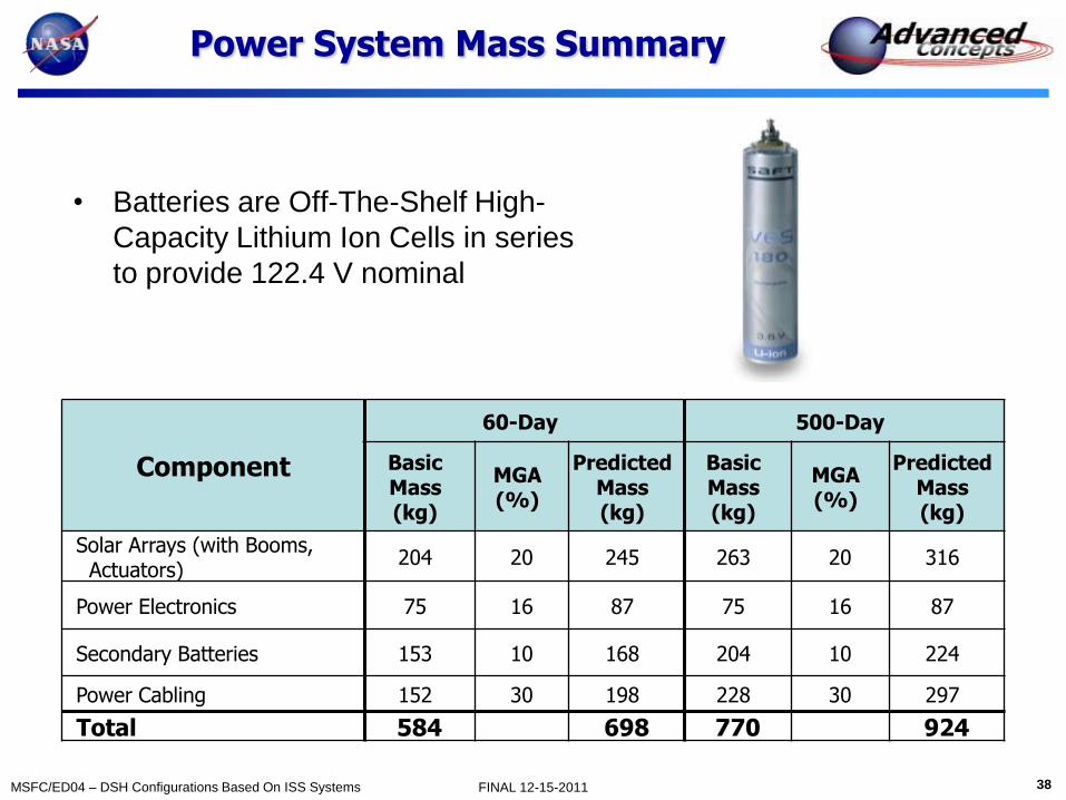
Power System Mass Summary
• Batteries are Off-The-Shelf High-
Capacity Lithium Ion Cells in series
to provide 122.4 V nominal
Component
60-Day 500-Day
Basic Mass (kg)
MGA (%)
Predicted Mass (kg)
Basic Mass (kg)
MGA (%)
Predicted Mass (kg)
Solar Arrays (with Booms, Actuators)
204 20 245 263 20 316
Power Electronics 75 16 87 75 16 87
Secondary Batteries 153 10 168 204 10 224
Power Cabling 152 30 198 228 30 297
Total 584 698 770 924

39 MSFC/ED04 – DSH Configurations Based On ISS Systems FINAL 12-15-2011
Avionics
Pete Capizzo
December 15, 2011

40 MSFC/ED04 – DSH Configurations Based On ISS Systems FINAL 12-15-2011
Avionics – MPCV Derived
• The avionics for the DSH has been based on the MPCV crew vehicle avionics. This was judged to be a practical approach since the MPCV vehicle is largely a habitat vehicle with all the electronics required to operate ECLSS systems and provides a robust communications system with good ground link and local communications capabilities.
• The 500-Day habitat avionics is about the same as the 60-Day configuration, but has a much larger communication dish (1.5 m vs .75 m).
• External cameras are used to assist in Flexcraft/SEV mission operations, or EVAs, from a Hab flight control center.
4 Video cameras:
for monitoring EVAs,
Flexcraft, and SEV operations,
along with vehicle H&S
MPCV RCS provides station
keeping for the stack,
can be manually control from
the Flight Control Center
Ka and S-band HGA
180deg from MPCV HGA
Port
TCSPDU/RIU THCARS
CDRAOGA
Main Avionics
TCC
UPAWPA
Avionics
Crew
Qrtrs
CRS-Sabatier
Ops
Flt
Stor
X
overStorWMC
CHECS
Vehicle
Management
Computer
(VMC)
Communication
components
Power& Data
Unit (PDU)
Remote Interface
Unit (RIU)
Power& Data
Unit (PDU)
Remote Interface
Unit (RIU)
Vehicle Management
Computer (VMC)
Communication components

41 MSFC/ED04 – DSH Configurations Based On ISS Systems FINAL 12-15-2011
Avionics Mass Comparison
Sub-System
60-Day 500-Day
Basic
Mass
(kg)
MGA
(%)
Predicted
Mass
(kg)
Basic
Mass
(kg)
MGA
(%)
Predicted
Mass
(kg)
AR&D System 11 3 11 11 3 11
Command and Data Handling 220 18 260 220 18 260
Displays & Controls 134 18 158 134 18 158
Communications System 159 18 189 187 18 221
Intercom & Video 56 22 69 56 22 69
Instrumentation 45 30 59 54 30 71
IHM System 50 10 55 70 10 55
Avionics Cabling 290 30 376 348 30 453
Total
965 1176 1081 1321
42 MSFC/ED04 – DSH Configurations Based On ISS Systems FINAL 12-15-2011
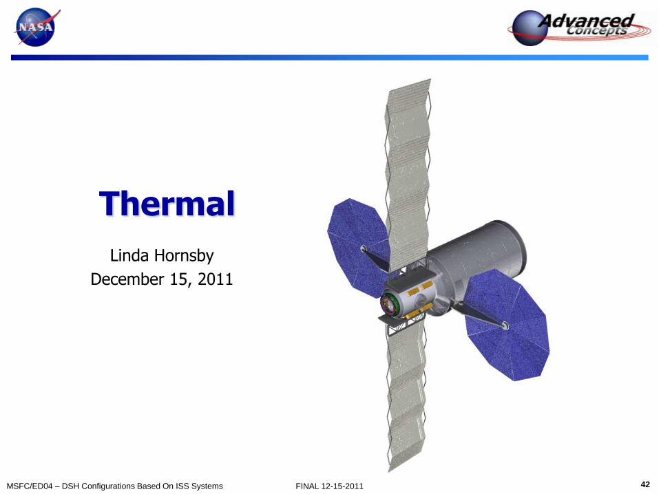
Thermal
Linda Hornsby
December 15, 2011

43 MSFC/ED04 – DSH Configurations Based On ISS Systems FINAL 12-15-2011
Thermal Control
• Active waste heat collection – redundant
internal and external pumped loops with
cold plates and heat exchangers
– DSH 60-Day mission metabolic and
equipment waste heat – 11,970 W
– DSH 500-Day mission metabolic and
equipment waste heat – 12,925 W
• Active waste heat rejection
– Radiators (with redundant loops) –
deployed, non-articulating in flight
• Passive waste heat rejection
– MPLM, HAB, tunnel pressure shell– multi-
layer insulation (MLI)
• Exterior temperature control
– MPLM, HAB, tunnel pressure shell– MLI
and heaters
– Exterior antennas, cameras, and gimbal
shelf– MLI, heaters, louvers, coatings
EEATCS/PVR Radiator ORU
External Passive
Thermal Control
PPA Centrifugal Pump
Rotating Assembly
Manual Flow Control Valve
Regenerative Heat Exchanger Two Way Mixing Valve

44 MSFC/ED04 – DSH Configurations Based On ISS Systems FINAL 12-15-2011
Thermal Mass Comparison by Mission
Subsystem
60-Day 500-Day
Basic
Mass
(kg)
MGA
(%)
Predicted
Mass
(kg)
Basic
Mass
(kg)
MGA
(%)
Predicted
Mass
(kg)
Internal TCS Rack LT/MT 226 20 271 226 20 271
Internal Rack Support 270 20 324 300 20 360
Internal TCS Misc. 30 30 39 30 30 39
External Active TCS 376 15 432 376 15 432
External Passive TCS 155 20 187 199 20 239
External Heat Rejection Sys. 1482 3 1526 1482 3 1526
Total 2539 2780 2613 2868

45 MSFC/ED04 – DSH Configurations Based On ISS Systems FINAL 12-15-2011
Environments Protection
Tiffany E. Russell
December 15, 2011

46 MSFC/ED04 – DSH Configurations Based On ISS Systems FINAL 12-15-2011
Crew Quarters Protection
• Environments Protection System
consists of two main components
– External Micrometeoroid Debris
Protection Shield (MDPS),
MPLM-derived
– Interior Radiation Water Wall
• Nominal 60 and 500-Day water wall:
– 0.55 cm thick polyethylene tank
– 9.9 cm thick water wall
– Total protection = 11 g/cm2
– Mass = 2850 kg
• Water wall provides a storm shelter
during a Solar Particle Event (SPE)
– Current design does not include
protection against Galactic Cosmic
Radiation (GCR)

47 MSFC/ED04 – DSH Configurations Based On ISS Systems FINAL 12-15-2011
Tank Configuration
• Water Wall surrounding crew quarters comprised of several tanks
Crew Quarter
Sub-System
60-Day 500-Day
Basic
Mass
(kg)
MGA
(%)
Predicted
Mass
(kg)
Basic
Mass
(kg)
MGA
(%)
Predicted
Mass
(kg)
Micro-Meteoroid & Debris
Protection System (MPDS) 1121 10 1233 1713 10 1884
Radiation Protection Tanks 332 5 349 332 5 349
Radiation Water 2518 3 2594 2518 3 2594
Total 3971 4176 4563 4827

48 MSFC/ED04 – DSH Configurations Based On ISS Systems FINAL 12-15-2011
Findings & Recommendations
David Smitherman
December 15, 2011
49 MSFC/ED04 – DSH Configurations Based On ISS Systems FINAL 12-15-2011
4 Crew / 60-Day Summary

50 MSFC/ED04 – DSH Configurations Based On ISS Systems FINAL 12-15-2011
4 Crew / 500-Day Summary

51 MSFC/ED04 – DSH Configurations Based On ISS Systems FINAL 12-15-2011
Mass Comparison
• DSH-ISS mass comparison to EXAMINE tool (parametric analysis)
– DSH-ISS utilizes flight hardware with known mass and other components at a high TRL
– 1.0 Structures includes multiple modules with more end-cones and docking mechanisms for the 500-Day case
– 4.0 Avionics includes a spare control station plus controls for robotics and propulsion elements
– 5.0 Thermal is sized for the LEO environment and utilizes more massive ISS thermal systems
– 6.0 Environmental protection includes more radiation shielding for SPE, and micrometeoroid debris shielding for the
LEO environment • Driving mass differences with EXAMINE Tool are in Structures, Avionics, Thermal, and Environmental Protection. The remaining differences are in bookkeeping
methods.

52 MSFC/ED04 – DSH Configurations Based On ISS Systems FINAL 12-15-2011
Future Work Suggestions
• Launch Vehicle Derived:
– SLS 2nd Stage Hydrogen Tank (Skylab II)
– Habitat built inside ELV shroud
• Radiation Protection Concepts:
– ISS sized modules enclosed by SLS 2nd stage hydrogen tank
– Investigate further the combining of water for radiation protection with the contingency water for the 500-Day case
• Artificial Gravity:
– Investigate artificial-gravity configurations with a vertically oriented multi-floor interior (similar to DSH D-RATS 2011 configuration) for end over end rotation of the vehicle
• Reusability:
– Explore mission scenarios that incorporate the DSH into a reusable system operating from the ISS or an Earth-Moon L1 or L2 Station
• Configuration:
– Look at advantages of using ISS STA Lab (HAB) and STA Node (Node 1) configuration, instead of the HAB and MPLM, for better docking arrangements with other elements.
– Consider commercial and international modules in production or available spares

53 MSFC/ED04 – DSH Configurations Based On ISS Systems FINAL 12-15-2011
Backup Materials

54 MSFC/ED04 – DSH Configurations Based On ISS Systems FINAL 12-15-2011
Ground Rules & Requirements
David Smitherman
December 15, 2011
55 MSFC/ED04 – DSH Configurations Based On ISS Systems FINAL 12-15-2011
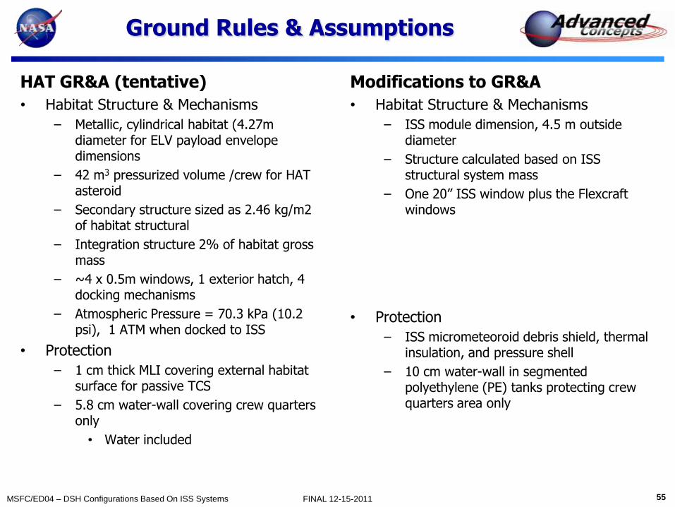
Ground Rules & Assumptions
HAT GR&A (tentative)
• Habitat Structure & Mechanisms
– Metallic, cylindrical habitat (4.27m diameter for ELV payload envelope dimensions
– 42 m3 pressurized volume /crew for HAT asteroid
– Secondary structure sized as 2.46 kg/m2 of habitat structural
– Integration structure 2% of habitat gross mass
– ~4 x 0.5m windows, 1 exterior hatch, 4 docking mechanisms
– Atmospheric Pressure = 70.3 kPa (10.2 psi), 1 ATM when docked to ISS
• Protection
– 1 cm thick MLI covering external habitat surface for passive TCS
– 5.8 cm water-wall covering crew quarters only
• Water included
Modifications to GR&A
• Habitat Structure & Mechanisms
– ISS module dimension, 4.5 m outside diameter
– Structure calculated based on ISS structural system mass
– One 20” ISS window plus the Flexcraft windows
• Protection
– ISS micrometeoroid debris shield, thermal insulation, and pressure shell
– 10 cm water-wall in segmented polyethylene (PE) tanks protecting crew quarters area only
56 MSFC/ED04 – DSH Configurations Based On ISS Systems FINAL 12-15-2011
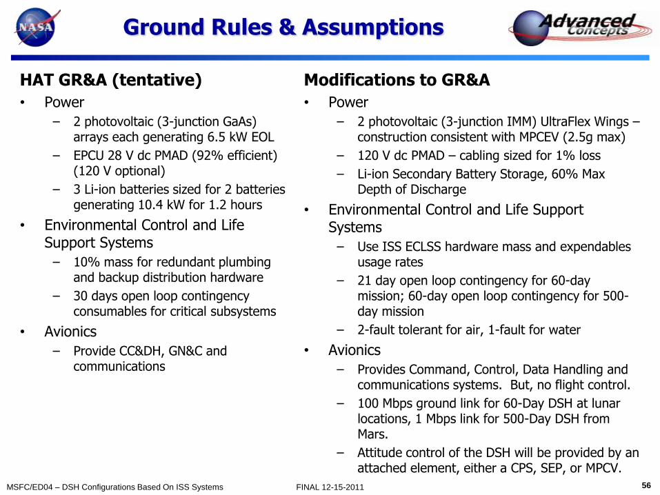
Ground Rules & Assumptions
HAT GR&A (tentative)
• Power
– 2 photovoltaic (3-junction GaAs) arrays each generating 6.5 kW EOL
– EPCU 28 V dc PMAD (92% efficient) (120 V optional)
– 3 Li-ion batteries sized for 2 batteries generating 10.4 kW for 1.2 hours
• Environmental Control and Life Support Systems
– 10% mass for redundant plumbing and backup distribution hardware
– 30 days open loop contingency consumables for critical subsystems
• Avionics
– Provide CC&DH, GN&C and communications
Modifications to GR&A
• Power
– 2 photovoltaic (3-junction IMM) UltraFlex Wings – construction consistent with MPCEV (2.5g max)
– 120 V dc PMAD – cabling sized for 1% loss
– Li-ion Secondary Battery Storage, 60% Max Depth of Discharge
• Environmental Control and Life Support Systems
– Use ISS ECLSS hardware mass and expendables usage rates
– 21 day open loop contingency for 60-day mission; 60-day open loop contingency for 500-day mission
– 2-fault tolerant for air, 1-fault for water
• Avionics
– Provides Command, Control, Data Handling and communications systems. But, no flight control.
– 100 Mbps ground link for 60-Day DSH at lunar locations, 1 Mbps link for 500-Day DSH from Mars.
– Attitude control of the DSH will be provided by an attached element, either a CPS, SEP, or MPCV.

57 MSFC/ED04 – DSH Configurations Based On ISS Systems FINAL 12-15-2011
Ground Rules & Assumptions
HAT GR&A (tentative)
• Thermal Control
– External fluid loop for heat acquisition using ammonia
– Internal fluid loop for heat acquisition using 60% prop glycol/water
– ~13 kW heat acquired from MM cabin & avionics rejected using ISS-type radiators.
– MLI covering external habitat surface for passive TCS.
– ~13 kW heat acquired from MM cabin & avionics rejected using ISS-type radiators w/ 10 mil Ag-teflon coating
• Crew Accommodations
– Standard suite for 60 & 500-Day deep space transfers (ref. Human Spaceflight Mission Analysis & Design)
– Sink(spigot), freezer, microwave oven, hand/mouth wash faucet, washer & dryer, 2 vacuums, laptop, trash compactor, printer, hand tools & accessories, test equipment, ergometer, photography equipment, exercise equipment, treadmill, table
Modifications to GR&A
• Thermal Control
– Active waste heat collection/rejection
• Redundant internal pumped water loop
• Redundant external pumped ammonia loop
• ISS LTL/MTL TCS components (pump package, filters, valves, HX, QDs, etc.)
• ISS External TCS components (pump package, filters, valves, HX, QDs, etc.)
• Deployed, non-articulating ISS PVR radiator.
– Exterior shell thermal control
• 19-layers DAK MLI, Nomex outer layer
• Areal density estimated at .5 kg/m2
• Shell heaters on HAB, MPLM, and tunnel
• Crew Accommodations
– No freezer, shower or washer & dryer for 60-day mission
– Add freezer for 500-day mission.

58 MSFC/ED04 – DSH Configurations Based On ISS Systems FINAL 12-15-2011
Ground Rules & Assumptions
HAT GR&A (tentative)
• Reserves
– Margin growth Allocation - 20% of basic mass
– Project Manager’s Reserve - 10% of basic mass
• Internal bulkhead with airlock services
– For contingent EVAs after NEO ops
• Reusability
– Reusable, 10 year lifetime minimum
• Spares
– 1500 kg spares mass bogey assigned by DRM team needs verification by subsystem experts related to LOC/LOM (unclear what is captured here: EVA Spares?, ECLSS Spares)
Modifications to GR&A
• Reserves
– Margin growth allocation is variable depending on individual component TRLs (Average is 8% for 60-Day case; 6% for 500-Day case)
– Project Manager’s Reserve - 10% of predicted total wet mass
• Internal bulkhead with airlock services
– No internal bulkhead required; contingency airlock in tunnel
• Reusability
– Reusable if transportation system returns to ISS for vehicle refurbishment
• Spares
– Operational spares of ~100 kg estimated for all but ECLSS
– ECLSS spares taken from ISS usage and mass for either mission length.
• ~800 kg for 60-Day case
• ~1800 kg for 500-Day case

59 MSFC/ED04 – DSH Configurations Based On ISS Systems FINAL 12-15-2011
Ground Rules & Assumptions
Additional Assumptions
• Habitat sized for 4 crew, 60-Day missions & 4 crew, 500-Day missions
• 60-Day Missions include
– EM L1 and EM L2 Missions
– GEO Satellite Servicing
– ES L2 Missions
– Lunar orbit Missions
– Microgravity Free-flyer
• 500-Day Missions include
– Some near-Earth asteroid missions
– Mars transit missions
• Sized for Existing Launch Vehicle Systems
– DSH exceeds mass an ELV can place in a 407km by 407km orbit (capability ~23mt)
– DSH can be broken down into smaller modular elements for ELV launch and/or outfitted at ISS
• Assembled and serviced at ISS
• Propulsion and Control provided by CPS, MPCV, and/or SEP
• DSH will provide supporting power, utilities, & ECLSS for attached vehicles during transit mode

60 MSFC/ED04 – DSH Configurations Based On ISS Systems FINAL 12-15-2011
Configuration
Mike Baysinger
December 15, 2011

61 MSFC/ED04 – DSH Configurations Based On ISS Systems FINAL 12-15-2011
60-Day Launches
Xx kg ≤ Mass ≤ xx,000kg

62 MSFC/ED04 – DSH Configurations Based On ISS Systems FINAL 12-15-2011
60-Day Launches
Xx kg ≤ Mass ≤ xx,000kg
63 MSFC/ED04 – DSH Configurations Based On ISS Systems FINAL 12-15-2011
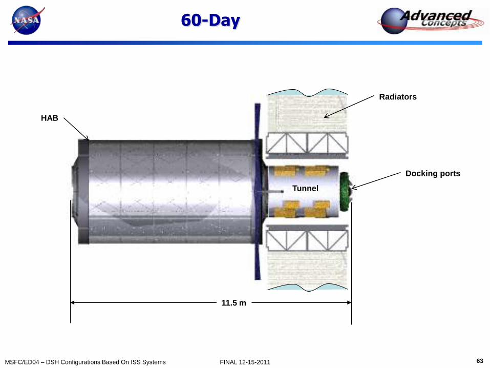
60-Day
HAB
Docking ports
Tunnel
Radiators
11.5 m

64 MSFC/ED04 – DSH Configurations Based On ISS Systems FINAL 12-15-2011
60-Day
Habitable volume=56 m3
Stowage volume= 16 m3

65 MSFC/ED04 – DSH Configurations Based On ISS Systems FINAL 12-15-2011
60-Day
66 MSFC/ED04 – DSH Configurations Based On ISS Systems FINAL 12-15-2011
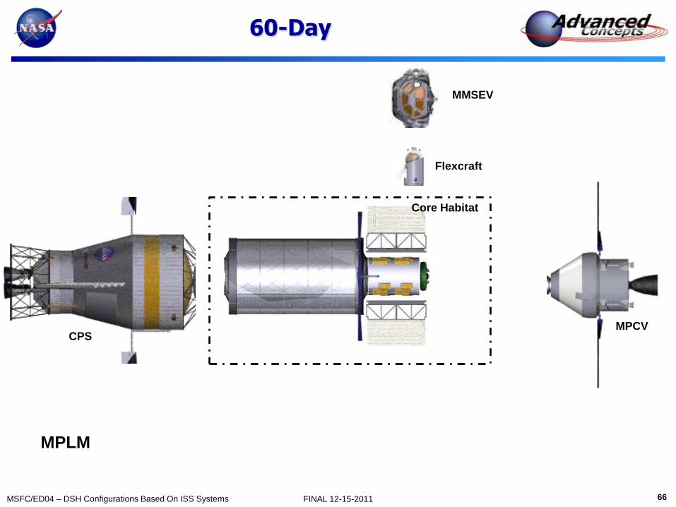
60-Day
MPLM
Core Habitat
MPCV
Flexcraft
MMSEV
CPS

67 MSFC/ED04 – DSH Configurations Based On ISS Systems FINAL 12-15-2011
60-Day

68 MSFC/ED04 – DSH Configurations Based On ISS Systems FINAL 12-15-2011
60-Day

69 MSFC/ED04 – DSH Configurations Based On ISS Systems FINAL 12-15-2011
500-Day Launches
HAB MPLM, Tunnel
Radiators, Solar Arrays
x,000kg ≤ Mass ≤ x,000kg
70 MSFC/ED04 – DSH Configurations Based On ISS Systems FINAL 12-15-2011
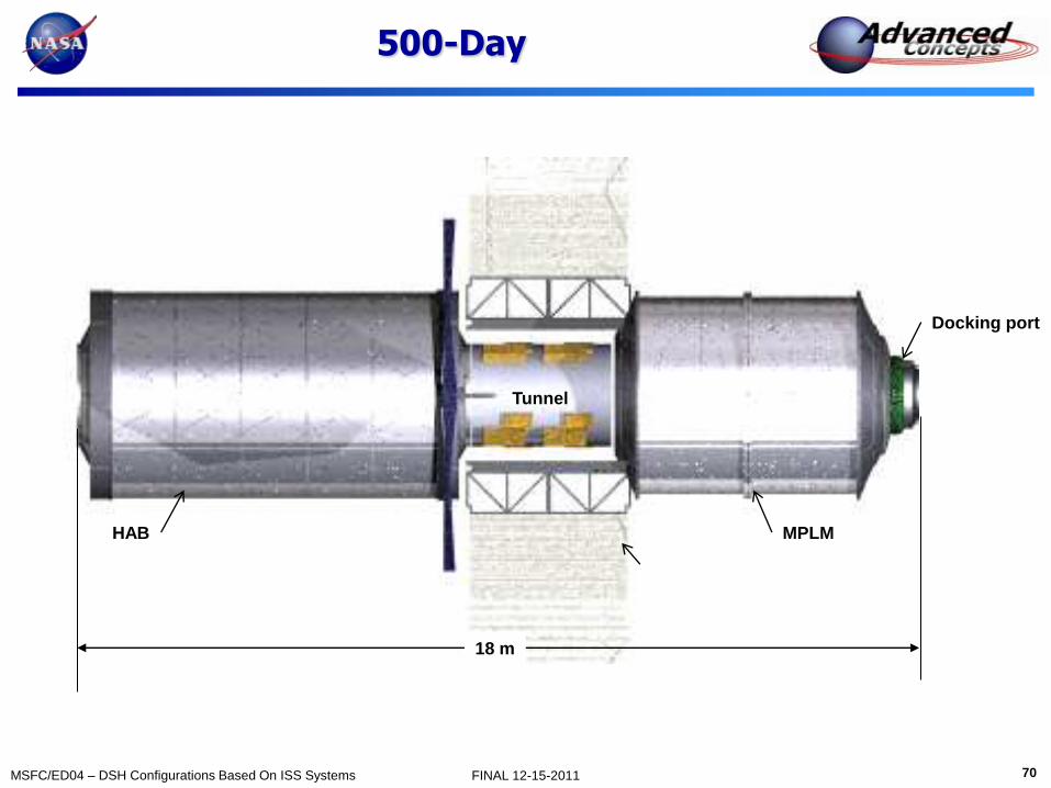
500-Day
HAB
Docking port
Tunnel
18 m
MPLM

71 MSFC/ED04 – DSH Configurations Based On ISS Systems FINAL 12-15-2011
500-Day
HAB
Tunnel
MPLM STA HAB:
Pressurized volume = 107 m3
Habitable volume = 56 m3
Stowage volume = 16 m3
MPLM:
Pressurized volume = 76 m3
Habitable volume = 25 m3
Stowage volume = 33 m3

72 MSFC/ED04 – DSH Configurations Based On ISS Systems FINAL 12-15-2011
500-Day
HAB
Tunnel
MPLM
73 MSFC/ED04 – DSH Configurations Based On ISS Systems FINAL 12-15-2011
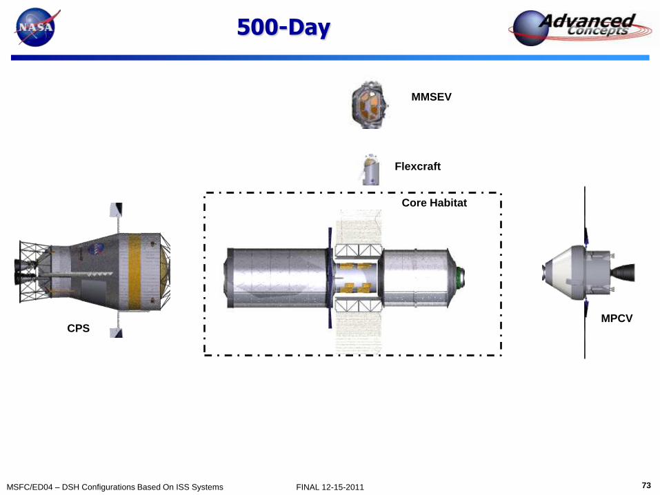
500-Day
Core Habitat
MPCV
Flexcraft
MMSEV
CPS
74 MSFC/ED04 – DSH Configurations Based On ISS Systems FINAL 12-15-2011
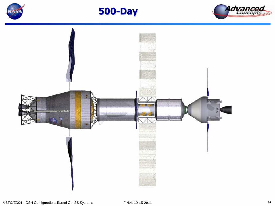
500-Day

75 MSFC/ED04 – DSH Configurations Based On ISS Systems FINAL 12-15-2011
500-Day
76 MSFC/ED04 – DSH Configurations Based On ISS Systems FINAL 12-15-2011
Mass
Dauphne Maples
December 15, 2011

77 MSFC/ED04 – DSH Configurations Based On ISS Systems FINAL 12-15-2011
Mass Summary: 60 Days
Basic Mass (kg) MGA (%) MGA (kg) Predicted Mass (kg)
Mass Breakdown Structure
1.0 7831.30 14.94% 1170.21 9001.51
2.0 0.00 0.00% 0.00 0.00
3.0 584.36 19.46% 113.70 698.06
4.0 964.72 22.03% 212.57 1177.29
5.0 2539.40 9.46% 240.15 2779.55
6.0 3971.00 5.14% 204.24 4175.24
7.0 3856.00 13.57% 523.10 4379.10
8.0 664.00 3.96% 26.32 690.32
9.0 271.00 0.28% 0.75 271.75
20681.78 12.04% 2491.04 23172.81
10.0 1,204.00 3.00% 36.12 1240.12
11.0 1,207.00 4.95% 59.80 1266.80
12.0 415.00 10.00% 41.50 456.50
13.0 0.00 0.00% 0.00 0.00
DSH Wet Mass 22,303.78 26,136.23
Project Manager's Reserve (PMR) 2,613.62
Total Wet Mass w/PMR 28,749.85
Dry Mass
Stowed Provisions
Consumables
Non-Prop Fluids
RCS
MEL - DSH 60 Day Case
Structures
Power
Propulsion
Avionics
EVA
ECLSS
Crew Systems
Environmental Protection
Thermal
78 MSFC/ED04 – DSH Configurations Based On ISS Systems FINAL 12-15-2011
Mass Summary: 500 Days
Basic Mass (kg) MGA (%) MGA (kg) Predicted Mass (kg)
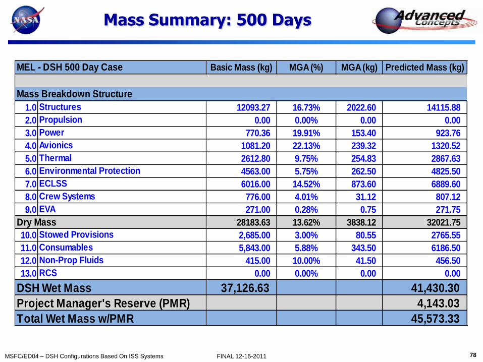
1.0 12093.27 16.73% 2022.60 14115.88
2.0 0.00 0.00% 0.00 0.00
3.0 770.36 19.91% 153.40 923.76
4.0 1081.20 22.13% 239.32 1320.52
5.0 2612.80 9.75% 254.83 2867.63
6.0 4563.00 5.75% 262.50 4825.50
7.0 6016.00 14.52% 873.60 6889.60
8.0 776.00 4.01% 31.12 807.12
9.0 271.00 0.28% 0.75 271.75
28183.63 13.62% 3838.12 32021.75
10.0 2,685.00 3.00% 80.55 2765.55
11.0 5,843.00 5.88% 343.50 6186.50
12.0 415.00 10.00% 41.50 456.50
13.0 0.00 0.00% 0.00 0.00
DSH Wet Mass 37,126.63 41,430.30
Project Manager's Reserve (PMR) 4,143.03
Total Wet Mass w/PMR 45,573.33
Non-Prop Fluids
RCS
ECLSS
Consumables
Environmental Protection
Crew Systems
EVA
Dry Mass
Stowed Provisions
MEL - DSH 500 Day Case
Structures
Mass Breakdown Structure
Propulsion
Thermal
Power
Avionics

79 MSFC/ED04 – DSH Configurations Based On ISS Systems FINAL 12-15-2011
Predicted Mass Comparison: 60 Vs. 500 Days
60 Day 60 Day 500 Day 500 Day
EXAMINE Tool EXAMINE Tool
Mass Breakdown Structure Mass (kg) Mass (kg) Mass (kg) Mass (kg)
1.0 3,820.00 9,001.51 5,629.00 14,115.88
2.0 0.00 0.00 0.00 0.00
3.0 937.00 698.06 1,141.00 923.76
4.0 453.00 1,177.29 453.00 1,320.52
5.0 539.00 2,779.55 699.00 2,867.63
6.0 2,213.00 4,175.24 2,323.00 4,825.50
7.0 2,599.00 4,379.10 8,391.00 6,889.60
8.0 790.00 690.32 2,583.00 807.12
9.0 635.00 271.75 635.00 271.75
23,172.81 32,021.75
10.0 3,271.00 1,240.12 5,512.00 2,765.55
11.0 212.00 1,266.80 1,084.00 6,186.50
12.0 0.00 456.50 0.00 456.50
13.0 0.00 0.00 0.00 0.00
26,136.23 41,430.30
Project Manager's Reserve (PMR) 2,613.62 4,143.03
Total Wet Mass w/PMR 18,448.00 28,749.85 34,391.00 45,573.33
DSH Wet Mass
Consumables
Environmental Protection
RCS
Non-Prop Fluids
Dry Mass
Stowed Provisions
ECLSS
Crew Systems
EVA
Thermal
MEL - DSH Comparison
Avionics
Power
Structures
Propulson
80 MSFC/ED04 – DSH Configurations Based On ISS Systems FINAL 12-15-2011
Crew Systems
Brand Griffin
December 15, 2011
81 MSFC/ED04 – DSH Configurations Based On ISS Systems FINAL 12-15-2011
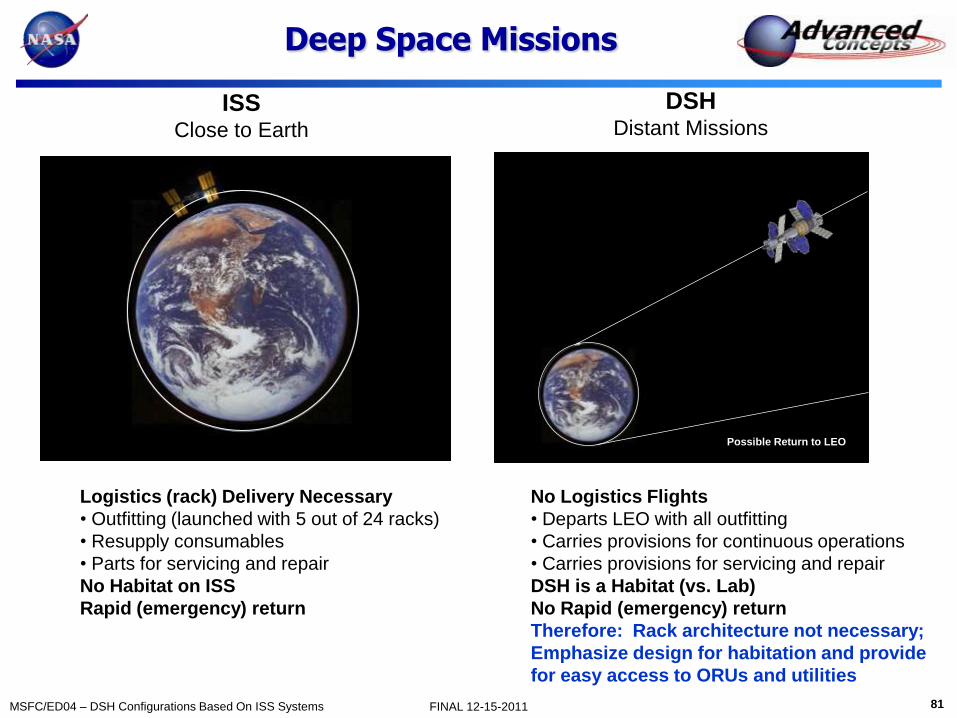
Deep Space Missions
ISS Close to Earth
DSH Distant Missions
Logistics (rack) Delivery Necessary
• Outfitting (launched with 5 out of 24 racks)
• Resupply consumables
• Parts for servicing and repair
No Habitat on ISS
Rapid (emergency) return
No Logistics Flights
• Departs LEO with all outfitting
• Carries provisions for continuous operations
• Carries provisions for servicing and repair
DSH is a Habitat (vs. Lab)
No Rapid (emergency) return
Therefore: Rack architecture not necessary;
Emphasize design for habitation and provide
for easy access to ORUs and utilities
Possible Return to LEO

82 MSFC/ED04 – DSH Configurations Based On ISS Systems FINAL 12-15-2011
Rack vs. Shell/ORU
Standoff (4)
Structure and Utilities
Rack rotates
to the center
ISSUE: Same size racks do not accommodate different functions
• Crew activities package differently than subsystems • Enclosures
• Multiple crew
• Subsystems have different access requirements • Single layer (don’t have to remove a component to get to another)
• Service while functioning
• Large aisle way • All rack swing against long axis
• Designed around infrequent operation
Deep
Compartment Open
Stow
Stow/
Subsystem
Equip
Pallet
Equip
Pallet
Easy access
utility packaging
(two sides)
Local Vertical
Open web
Longeron
Cable Tray (4)
Flex lines allow racks to
rotate and remain operational
ISS Rack Based Layout Shell/ORU Based Layout
Designed for ORU level Interchangeability Two-sided equipment pallet
Crew activities in wall
Subsystem to ceiling/floor
Dedicated utility interface
Local vertical for crew Head-to-toe air flow
Overhead lighting
Easy access Cable Tray

83 MSFC/ED04 – DSH Configurations Based On ISS Systems FINAL 12-15-2011
The Real ISS
Waste Hygiene Compartment
Utility Connections
US Lab (Destiny)
84 MSFC/ED04 – DSH Configurations Based On ISS Systems FINAL 12-15-2011
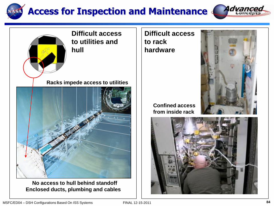
Access for Inspection and Maintenance
Difficult access
to utilities and
hull
No access to hull behind standoff
Enclosed ducts, plumbing and cables
Racks impede access to utilities
Difficult access
to rack
hardware
Confined access
from inside rack

85 MSFC/ED04 – DSH Configurations Based On ISS Systems FINAL 12-15-2011
Habitation and Autonomy 500-Days without resupply
Activity DSH Accommodation
Privacy, personal space Large crew quarters, no through traffic, quiet end of module, acoustic insulation, personal control over temperature/air flow, adjustable lighting, data/power access, private communications
Eating, group meetings Open area to accommodate all 4 crew, restraints for food and crew, one meal together per day
Food Preparation Open area, microwave, refrigerator
Sleeping Crew quarters, weightless restraints, change of bedding, radiation protection (storm shelter)
Exercise Open area, adjustable air flow, easily cleaned, scheduling should not conflict with common meal
Waste Mgt Larger enclosure than ISS, adjustable airflow, easily cleaned
Personal Hygiene Enclosed area for whole body cleansing, hand wash, brushing teeth, personal grooming
Recreation, off-duty time Crew choice, window, exercise, crew quarters or galley wardroom
Mission Operations Science and flight operation workstations
Autonomy DSH Accommodations
Servicing Easy access to ORUs and utilities. Service while operational.
Consumables Bring all consumables for entire mission (plus margin)
Spares Hot spares, stored spares, design for repair or work around

86 MSFC/ED04 – DSH Configurations Based On ISS Systems FINAL 12-15-2011
Weightless Posture
~1.74 m (68”)
Zero g Projected Height
~1.38 m (54”)
95 %ile US Male 5 %ile Female

87 MSFC/ED04 – DSH Configurations Based On ISS Systems FINAL 12-15-2011
Assumed Crew Schedule
Guidelines: Common sleep time
Eat one meal together (dinner)
Dinner is one hour (prep, eat, cleanup)
Two hours exercise
One person at a time for exercise
Exercise does not interfere with meals
Four hours off-duty (not exercise or dinner)
At least one hour off-duty before sleep
Crew 1 2 3 4 5 6 7 8 9 10 11 13 14 15 16 17 18 19 20 21 22 23 24
A
B
C
D
Sleep
Work
Exercise
Dinner
Off Duty
Hour of the Day

88 MSFC/ED04 – DSH Configurations Based On ISS Systems FINAL 12-15-2011
Alternate Cross Sections
ISS-Rack
Symmetrical
2.2 m Aisle
“Small compartments
Complex utilities
Unforgiving
Shell/ORU
Symmetrical
~1.5 m Aisle
Moderate compart.
Two person translation
Good packaging depth
Endcone crew qrtrs
Works with 50” hatch
Shell/ORU
Symmetrical
1.0 m Aisle
Ample compart.
Tight two per. Trans.
Deep packaging
Wall crew qrtrs
May work with 50” hatch
Can be combined
Shell/ORU
Asymmetrical
1.0 m Aisle
Compartment
Generous compart.
Tight two per. Trans.
Good packaging depth
Wall crew qrtrs (inline)
May work with 50” hatch
Shell/ORU
Asymmetrical
1.0 m Aisle
Quadrant
Generous compart.
Tight two per. Trans.
Good packaging depth
Wall crew qrtrs (stakced)
May work with 50” hatch
Favored

89 MSFC/ED04 – DSH Configurations Based On ISS Systems FINAL 12-15-2011
Utility Layout Comparison
X Over
Racks
Ceiling Floor Wall Wall
Utilities
End X-Over
• Long utility runs
• Larger dia ducts
• Noise
Standoff Lighting
• Two sides
• Easily obscured
•Standoff Air Supply
• Two sides
• Easily obscured
X Over
Ceiling Floor Wall Wall
Utilities
ISS Rack Based Shell/ORU Based
Middle X-Over
• Short utility runs
• Smaller dia ducts
• Less Noise
• More usable length
Central Lighting
• One light
• Good illumination
•Central Air Supply
• One diffuser
• Good distribution
Standoff Standoff Standoff Standoff Cable Tray Cable Tray Cable Tray Cable Tray
No Utilities Transverse
Utilities

90 MSFC/ED04 – DSH Configurations Based On ISS Systems FINAL 12-15-2011
EZ Access Architecture
Longerons/
cable tray (4)
(Combined structure and
cable tray)
Utilities
Single layer
(For direct access and
efficient utility routing)
EZ Access Pallet
Rotating subsystem
mounting frame
(Single layer ORUs on
Both sides of frame)
Transverse Utility
Beam
Seat track or similar
(top surface)
Seat track or similar
(edge)
Floor and
ceiling panels
(open iso-grid provides
visibility to systems and
attach points for
mounting work lights
fans, etc,)

91 MSFC/ED04 – DSH Configurations Based On ISS Systems FINAL 12-15-2011
Axial Modularity
ISS US Lab-6 Rack Bays
(24 racks)
~ 1.05 m Repeat
Coupled with utilities
No fractional racks
(large dimension
impacts layout flexibility)
No Rack Bays
Linear structure (e.g., aircraft seat track)
~ 2 cm Repeat
Decoupled with utilities
(small dimension allows layout flexibility)
Seat Track and Attachments
ISS Shell/ORU
92 MSFC/ED04 – DSH Configurations Based On ISS Systems FINAL 12-15-2011
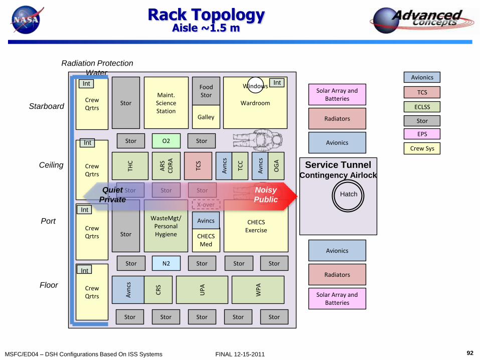
Rack Topology Aisle ~1.5 m
Avn
cs
Wardroom Stor
THC
AR
S C
DR
A
N2
Crew Qrtrs
Galley
CHECS Exercise
WasteMgt/ Personal Hygiene
Ceiling
Floor
Port
Starboard
Crew Qrtrs
Crew Qrtrs
Radiation Protection
Water
Solar Array and Batteries
Radiators
Avionics
Solar Array and Batteries
Radiators
Avionics
Hatch
Service Tunnel Contingency Airlock
Int
Int
Int
Avionics
TCS
ECLSS
Stor
EPS
Crew Sys
Food Stor
UP
A
Windows Int
WP
A
Stor
X-over
Stor
Stor
Stor Stor Stor
O2 Stor Stor
Stor Stor
TCS
Crew Qrtrs
Int
Maint. Science Station
CHECS Med
Avincs
TCC
Avn
cs
CR
S
Avn
cs
OG
A
Stor Stor
Stor Stor Stor Quiet
Private
Noisy
Public

93 MSFC/ED04 – DSH Configurations Based On ISS Systems FINAL 12-15-2011
Layout Rationale Non Rack Based (1.5 m aisle)
Crew Quarters • Individual
• Acoustic and visual privacy
• Quiet end of module
• End cone for extra volume
SPE Radiation Protection • “Shelter” approach (retreat during storm
and surrounds area where crew spends
most time
• Potable water
Local Vertical • Port and starboard racks for crew
functions ( e.g., wardroom, waste mgt)
• Floor and ceiling for subsystems (e.g.,
ECLSS, TCS)
Stowage • Acoustic insulation
• Radiation protection
Wardroom • Open area with window
• Dining and group gathering
CHECS • Open area for exercise
• Adjacent to medical equipment
Suit Stowage (2) • In stowage area
• Used for contingency
Hatches • Hab (50 inch)
• MPCV (LIDS)
• FlexCraft docking
Service Tunnel • Length for ISS radiators
• Diameter (Suits + translation)
• Diameter to allow external
packaging of batteries, arrays,
avionics and radiators
Waste Mgt • Not adjacent to Crew Qrtrs or Galley
• Adjacent to ECLSS racks in ceiling
Utility Crossover • Return air and water
• End-cone location
Maint/Science • Workstation
• Open to aisle

94 MSFC/ED04 – DSH Configurations Based On ISS Systems FINAL 12-15-2011
Longitudinal Sections
Avionics
TCS
ECLSS
Stor
EPS
Crew Sys
Longitudinal Sections Port Starboard
TCS THC ARS
CDRA OGA
Avionics
TCC
UPA WPA
Avncs
Crew
Qrtrs
CRS-Sabatier
PDU/RIU TCS PDU/RIU THC ARS
CDRA OGA
Avionics
TCC
UPA WPA
Avncs
Crew
Qrtrs
CRS-Sabatier
Galley Stor Ward
room
Science
Ops
Flt
Stor X
over
Stor WMC CHECS
Crew
Qrtrs
CHECS
(exercise)
Galley
WMC
Ops
Flt
Wardrm
X
over
Stor
CHECS
(med)
Stor
Science\
Maint.
Transverse Section AA Plan
A
A
A
A

95 MSFC/ED04 – DSH Configurations Based On ISS Systems FINAL 12-15-2011
Crew Quarters
Radiation
Protection
Crew Quarters (4)
DSH (~ 4 m3 each) ISS (~2 m3 each)

96 MSFC/ED04 – DSH Configurations Based On ISS Systems FINAL 12-15-2011
DSH Waste Hygiene Compartment
Utility Cross Over
Aisle Hygiene Station
(Brush teeth if WHM
is occupied)
Access to WHC
hardware
Commode (position takes advantage
of shell curvature)
Direct access to hull
Restraints
Open area for whole
body cleansing)
Aisle way access
to stowage
WHG access
to stowage Edge of floor
ISS DSH Interior WHC Exterior WHC Plan Plan Section Section

97 MSFC/ED04 – DSH Configurations Based On ISS Systems FINAL 12-15-2011
Accessibility Zoning
No immediate
access to hull
Zone Access
A Immediate Physical & Visual
B Indirect
C Infrequent
• No access
behind standoff
• Utilities enclosed
“compartment” depth
less than aisle width
ISS Stowage
ISS Access Shell/ORU
98 MSFC/ED04 – DSH Configurations Based On ISS Systems FINAL 12-15-2011
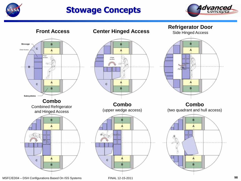
Stowage Concepts
Front Access Center Hinged Access Refrigerator Door
Side Hinged Access
Combo Combined Refrigerator
and Hinged Access
Combo (upper wedge access)
Combo (two quadrant and hull access)

99 MSFC/ED04 – DSH Configurations Based On ISS Systems FINAL 12-15-2011
Crew Systems Mass by Mission
60-Day Mission 500-Day Mission 60-Day Mission 500-Day Mission
Component Basic
Mass (kg)
MGA
%
Predicted
Mass (kg)
Basic
Mass (kg)
MGA
%
Predicted
Mass (kg)
Galley 150 3 154 150 3 154
Wardroom 50 3 52 50 3 52
Crew Quarters 248 5 260 248 5 260
Restraints 24 3 25 24 3 25
Crew Health Care (Medical) 73 3 75 173 3 178
Crew Health Care (Exercise) 91 3 94 91 3 94
Personal Laptops 16 3 16 16 3 16
General Illumination 12 15 14 24 15 28
Crew Systems Total 664 690 776 802
Stowed Provisions: Personal 80 3 82 100 3 103
Housekeeping Expendables 20 3 21 166 3 171
Operational Spares 100 3 103 175 3 180
Maintenance Equipment 40 3 41 80 3 82
Photography 4 3 4 4 3 4
EVA: Provisions 30 3 31 60 3 62
EVA Suits 246 0.0 246 246 0.0 246
Airlock Services 25 3 25 25 3 25
Total 1210 1243 1632 1675

100 MSFC/ED04 – DSH Configurations Based On ISS Systems FINAL 12-15-2011
Environmental Control & Life Support Systems (ECLSS)
Janie Miernik
December 15, 2011

101 MSFC/ED04 – DSH Configurations Based On ISS Systems FINAL 12-15-2011
ECLSS Subsystems
Design Approach, Assumptions, Ground Rules • Closed-loop ECLSS was designed and has been demonstrated for a crew of six on
ISS, so application to a 4-man crew offers some extra margin. Most systems would only run in daily batches, 10 hrs/day.
• Mass of ISS subsystems, expendables, usage and failure rates are used in determining the mass allotments of ECLSS components and spares.
– Two Water ISPR racks are included in ISS-packaged configuration and remain TRL 9.
– The rest of the ECLSS subsystems are repackaged in DSH, believing that better configuration and lighter secondary structure can be developed; these subsystems are assigned TRL 7.
• At least single failure tolerance through spare ORUs, back-up contingency, or a second stowed subassembly is accounted for with spares and expendable mass.
• Open-loop contingency critical life support supplies are included: 21-days for the 60-day mission and 60-Days for the 500-day mission.
• Carbon dioxide removal is 2-fault tolerant for both missions with a spare CRA and LiOH back-up.
102 MSFC/ED04 – DSH Configurations Based On ISS Systems FINAL 12-15-2011
ECLSS Consumables
Design Approach • 21 days of open-loop contingency margin on consumables (food, water, O2) is
included for the 60-day mission and 60-Days contingency for the 500-day mission.
• ISS water balance is well characterized by several years of semi-open loop operation, and recently with periods of nearly closed-loop operation.
• Food mass was calculated with 35% average moisture content for the solid food.
• A daily amount of water is calculated for hygiene, urinal flush and oxygen generation.
• Potable water for make-up and contingency will be stored in ISS qualified bellows tanks that hold/deliver about 70/65 kg of water each. Many tanks will needed for 60-Days contingency on the longer mission.
• Since oxygen generation with the ISS-sized OGA is sufficient to meet the needs of a crew of four, little more than contingency O2 need be carried.
• N2 will be carried for leakage and contingency EVA.
• ECLSS spares, expendables, water, food, and collected waste are “wet” and will provide radiation protection throughout mission.
– Expended urine brine and waste management canisters will be stowed, rather than jettisoned to maintain wet radiation protection.

103 MSFC/ED04 – DSH Configurations Based On ISS Systems FINAL 12-15-2011
ECLSS
Description of Systems
• Air
– Carbon Dioxide Removal Assembly (CDRA)
(ISS Heritage)
• Feeds Sabatier
• Lithium hydroxide (LiOH) canisters are stored for back-
up CO2 removal.
– Temperature and Humidity Control (THC)
(ISS Heritage)
• Feeds WPA
– Trace Contaminant Control System (TCCS)
(ISS Heritage)
– Atmosphere Control and Supply System (ACSS)
(ISS Heritage)
– Oxygen Generation Assembly (OGA) (ISS Heritage)
• Creates O2 (and H2) from H2O; feeds Sabatier
– Carbon dioxide reduction – Sabatier (ISS Heritage)
• Creates H2O from H2 and CO2
• Currently no Vacuum Access on DSH
CDRA

104 MSFC/ED04 – DSH Configurations Based On ISS Systems FINAL 12-15-2011
ECLSS
Description of Systems • Water
– Water Processor Assembly (WPA) (ISS Heritage)
– Urine Processor Assembly (UPA) (ISS Heritage) Together with WPA recovers water for reuse and is called Water Recovery and Management (WRM).
• Waste Hygiene Compartment (WHC) (ISS
Heritage)
– Waste is collected and compacted and has a high water content.
• Expendables and Spares
– Mass derived from ISS mass and usage.
– Spares are mostly for air regeneration systems.
– Expendables are mostly for water regeneration systems.
– Expendables and spares are all “wet” for water regeneration hardware. Water Reclamation Rack
105 MSFC/ED04 – DSH Configurations Based On ISS Systems FINAL 12-15-2011
ECLSS
Description of Systems
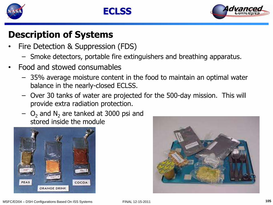
• Fire Detection & Suppression (FDS)
– Smoke detectors, portable fire extinguishers and breathing apparatus.
• Food and stowed consumables
– 35% average moisture content in the food to maintain an optimal water balance in the nearly-closed ECLSS.
– Over 30 tanks of water are projected for the 500-day mission. This will provide extra radiation protection.
– O2 and N2 are tanked at 3000 psi and stored inside the module

106 MSFC/ED04 – DSH Configurations Based On ISS Systems FINAL 12-15-2011
Comparison of Mission/Mass
60-Day Mission 500-Day Mission
ECLSS Subsystem Basic Mass
(kg)
MGA
%
Predicted
Mass (kg)
Basic Mass
(kg)
MGA
%
Predicted
Mass (kg)
Atmosphere Revitalization Sys (ARS) 337 20 404 562 20 674
Atmosphere Cont & Supply System (ACSS) 400 20 480 1200 20 1440
Temp & Humidity Control (THC) 149 20 179 149 20 179
Waste Hygiene Compartment (WHC) 455 20 546.00 455 20 546
Water Recovery & Man (WRM) 1300 3 1339 1300 3 1314
Atmosphere Regen (OGA/ CO2 Red Assy) 1000 20 1200 1600 20 1860
Fire Detection & Suppression /module 35 30 46 70 30 91
Potable Water Tanks 180 3 185 680 3 700
ECLSS Hardware Total 3856 4379 6016 6890
ECLSS Expendables 200 3 206 500 3 515
ECLSS Spares 730 3 752 1600 3 1648
H2O 634 3 653 2520 3 2596
Food, packaged 337 10 371 2403 10 2643
Atmosphere Regen (O2) 114 3 117 670 3 690
Atmosphere Regen (N2) leakage 122 3 126 250 3 258
Total 5993 6603 13959 15239

107 MSFC/ED04 – DSH Configurations Based On ISS Systems FINAL 12-15-2011
Structures
Janie Miernik
December 15, 2011
Multi-Purpose Logistics Module (MPLM)

108 MSFC/ED04 – DSH Configurations Based On ISS Systems FINAL 12-15-2011
Structures
Ground Rules & Assumptions • DSH cabin air pressure = 70.3 kPa (10.2 psi, .7 atm). 1 atm (14.7 psi, 101.3 kPa) when docked to
ISS on 60-Day mission demonstrator.
• ISS STA Lab/HAB Module has known mass and is fabricated, not qualified, so is TRL 8.
• MPLM design is used but additional CBM docking port added, TRL drops to 7.
• The interior secondary structure is conservatively estimated at 20% of the mass that must be
supported and is assigned TRL 8.
• The tunnel/contingency airlock structure mass is based on ISS airlock areal mass, is assumed to be
fabricated in a similar manner, and is assigned TRL 7. External secondary structure for radiators,
meteor debris shielding and power systems are estimated at 20% of the mass to be supported.
• All ports will be CBM-sized and use ISS mass for these components. A NASA Docking System
(NDS) adapter will be used for MPCV interface; mass found in NDS documentation.
• This configuration, layout, and structural mass was not analyzed for EELV launch loads, mass or
center of gravity limitations of the launch platform. A new launch adapter must be developed for
EELV launch to interface ISS elements and it is not included in stated mass.
• The projected mass needed for the missions exceed the cargo launch limitation of the modules,
some of the required DSH stowed mass must be launched to ISS by other means and installed at
ISS.
109 MSFC/ED04 – DSH Configurations Based On ISS Systems FINAL 12-15-2011
Structures
Launch Considerations
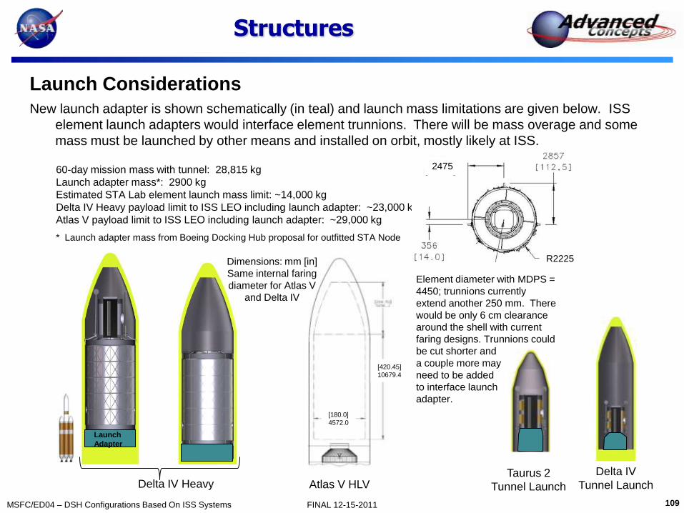
New launch adapter is shown schematically (in teal) and launch mass limitations are given below. ISS
element launch adapters would interface element trunnions. There will be mass overage and some
mass must be launched by other means and installed on orbit, mostly likely at ISS.
Delta IV Heavy Delta IV
Tunnel Launch Taurus 2
Tunnel Launch
60-day mission mass with tunnel: 28,815 kg
Launch adapter mass*: 2900 kg
Estimated STA Lab element launch mass limit: ~14,000 kg
Delta IV Heavy payload limit to ISS LEO including launch adapter: ~23,000 kg
Atlas V payload limit to ISS LEO including launch adapter: ~29,000 kg
* Launch adapter mass from Boeing Docking Hub proposal for outfitted STA Node
Launch
Adapter
[180.0]
4572.0
[420.45]
10679.4
Dimensions: mm [in]
Same internal faring
diameter for Atlas V
and Delta IV
Atlas V HLV
Element diameter with MDPS =
4450; trunnions currently
extend another 250 mm. There
would be only 6 cm clearance
around the shell with current
faring designs. Trunnions could
be cut shorter and
a couple more may
need to be added
to interface launch
adapter.
R2225
2475

110 MSFC/ED04 – DSH Configurations Based On ISS Systems FINAL 12-15-2011
Structures
Description of Modules and Components:
MPLM
• Length –5.5m (18 ft)
• Diameter – 4.5 m (14 ft)
• Power – MPLM currently accommodates 5 powered racks
– Two 1050 W
– Three 598 W
– Power, thermal and avionics will be enhanced for DSH missions.
• Pressurized Volume – 76.4 m3 (2772 cu ft)
• Habitable volume – 32.3 m3 (1144 cu ft)
• Mass, including 16 rack attachment blocks, MDPS, and 1 CBM for the 60-day mission: 3,767 kg (8,304 lbs) (2 CBMs for the 500-day mission)
– Primary Structure - 2770 kg (6108 lbs)
– MDPS - 592 kg (1305 lbs) (carried in Environmental Protection)
– Internal Structure - 404 kg (892 lbs)

111 MSFC/ED04 – DSH Configurations Based On ISS Systems FINAL 12-15-2011
Structures
Description of Modules and International Payload Racks
STA Lab/Hab
MPLM Tunnel ISPR
Length 8.5 m (27.4 m)
6.5m (19 ft)
3.2 m (10.5 ft)
Height 2 m (6.1 ft)
Cylindrical section length
7.2 m (25.6 ft)
4.9 m (15 ft)
3.2 m (10.5 ft)
Width 1.05 m (3.4 ft)
Diameter 4.3 m (14 ft)
4.3 m (14 ft)
2.5 m (7.6 ft)
Max. depth
.86 m (2.8 ft)
Pressurized volume
106 m3
76.4 m3 10 m3 Volume 1.57 m3
Mass of shell incl. CBMs and hatches
3833 kg (8450 lbs)
2502 kg (5516 lbs)
1284 kg (2204 lbs) ~25 kg/m2
areal mass
Mass of 6-post rack
105 kg (230 lbs)

112 MSFC/ED04 – DSH Configurations Based On ISS Systems FINAL 12-15-2011
Comparison of Mission/Mass
60-Day Mission 500-Day Mission
Structural Component Mass (kg)
MGA %
Predicted Mass (kg)
Mass (kg)
MGA %
Predicted Mass (kg)
STA Lab/Hab outfitted Pressure Shell 3833 10 4216 3833 10 4216
Hab Secondary Structure 2141 20 2569 2141 20 2569
MPLM outfitted Pressure Shell w/2
axial CBM ports 0 20 0 2502 20 3002
MPLM Secondary Structure 0 20 0 1 1704 20 2044
Tunnel/Ext. Secondary Structure 1782 20 2139 1815 20 2178
20” ISS Window 75 3 77 75 3 77
Total 7831 9002 12069 14087

113 MSFC/ED04 – DSH Configurations Based On ISS Systems FINAL 12-15-2011
Structural Issues Not Addressed
• Finite Element Analysis (FEA) FEA will be required for element shells and secondary structure because they are being
launch in a different way and used for a different application.
– EELV launch loads and configuration with launch adapter is different from shuttle
bay launch.
– Non-rack-based secondary structure attachment to pressure shell is different in
some locations.
– Non-rack-based secondary structure attachment and access mechanisms to
stowed and installed mass is different.
– Module axial CBM docking ports are modified (added or eliminated)
• Launch Adapter Evolved Expendable Launch Vehicle (EELV) launch will require a new interface to
existing module trunnions to launch these elements to space. The launch adapter mass
is not considered a part of the structural module in this study.
– A launch adapter mass/design developed for the STA Node in the 2010 Boeing
Docking Hub proposal is proposed to get the DSH to ISS for mission outfitting.
– This launch adapter may also have propulsion capability to enable docking to ISS
for mission outfitting.

114 MSFC/ED04 – DSH Configurations Based On ISS Systems FINAL 12-15-2011
Power System Leo L Fabisinski
December 15, 2011

115 MSFC/ED04 – DSH Configurations Based On ISS Systems FINAL 12-15-2011
Design Approach
• Since ISS is 150V and has a distributed power architecture not suitable to DSH, Use MPCV components instead.
• MPCV Power Electronics were adapted from ISS components.
• UltraFlex Arrays and Drive Actuators Scaled from MPCV are suitable for free-flying craft.

116 MSFC/ED04 – DSH Configurations Based On ISS Systems FINAL 12-15-2011
Solar Array Wing
Array Wing is Populated with
Multi-Junction Inverted
Metamorphic (IMM) Solar Cells
currently in development.
These offer Higher Conversion
Efficiency and Lighter Weight
than SOA Cells.

117 MSFC/ED04 – DSH Configurations Based On ISS Systems FINAL 12-15-2011
Solar Arrays
Since the Hab is in the middle of the complete stack, shadowing is a problem for some flight attitudes with respect to the sun, as shown below
If shadowing presents a
problem, deployment of
MPCV arrays may be delayed
and MPCV will require keep-
alive power from Hab or
CPS. Alternatively, MPCV
arrays may be turned edge-
on to the sun to minimize
shadow.

118 MSFC/ED04 – DSH Configurations Based On ISS Systems FINAL 12-15-2011
Power Electronics (MPCV Designs)
• Solar Array Switch Module (SASM) – derived from ISS Array Regulation Unit (ARU)
• 120V Power Switch Card – Derived from ISS Remote Power Control Module (RPCM)
• 120V Umbilical Switch Card – Derived from ISS RPCM
• 28V Power Switch Card - derived from ISS 28V converters
• Battery Controller – Derived from Mars Reconnaissance Orbiter
119 MSFC/ED04 – DSH Configurations Based On ISS Systems FINAL 12-15-2011
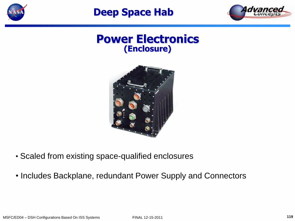
Power Electronics (Enclosure)
Deep Space Hab
• Scaled from existing space-qualified enclosures
• Includes Backplane, redundant Power Supply and Connectors

120 MSFC/ED04 – DSH Configurations Based On ISS Systems FINAL 12-15-2011
Secondary Battery
Deep Space Hab
• Each battery String consists of 34 SAFT VES 180 Cells in series to
achieve 122.4 V nominal potential.
• Mass Packing Factor of 1.35 used to size cell-balance electronics and
Enclosure

121 MSFC/ED04 – DSH Configurations Based On ISS Systems FINAL 12-15-2011
Deep Space Hab Mass Summary
Component
60-Day 500-Day
Basic Mass (kg)
MGA (%)
Predicted Mass (kg)
Basic Mass (kg)
MGA (%)
Predicted Mass (kg)
Solar Arrays (with Booms, Actuators)
204 2 245 263 20 316
Power Electronics 75 16 87 75 16 87
Secondary Batteries 153 10 168 204 10 224
Power Cabling 152 30 198 228 30 297
Total 584 698 770 924

122 MSFC/ED04 – DSH Configurations Based On ISS Systems FINAL 12-15-2011
Avionics
Pete Capizzo
December 15, 2011

123 MSFC/ED04 – DSH Configurations Based On ISS Systems FINAL 12-15-2011
DSH AES - Avionics
• Avionics Approach – The avionics system provides all command, control, data handling, and communications systems for the habitat.
– The avionics for this DSH has been based on the MPCV crew vehicle avionics. This was judged to be a practical approach since the MPCV vehicle is largely a habitat vehicle with all the electronics required to operate ECLSS systems and provides a robust communications system with good ground link and local comm capabilities.
• None of the MPCV propulsion or GN&C capabilities are included in the habitat.
– Much of the MPCV avionics is already under development and has higher levels of TRL. This approach is then lower risk and coast than new development, and can compliment a short development schedule.
– Using MPCV avionics as a baseline establishes good DSH commonality of avionics hardware with MPCV avionics. Spare parts stored in the habitat can be used in MPCV also.
• Commonality further reduces cost and risk
– It is basically a single hardware redundant system with some dual and triple fault tolerance provided by complementary systems.
• For example, the S-band system can provide the same communication functions as the Ka-band with some reduced performance.
• The two main computers are each a self checking pair system, making each one single fault tolerant itself, providing triple fault tolerances for the complete system.
– Using ISS avionics would mean using old/obsolete technology. ISS avionics was designed for ISS control. The DSH avionics needs to communicate with and control vastly different elements (MPCV, SEP, CPS, MMSEV, etc.)
• The MPCV avionics is better suited to interface with these different elements, and to communicate with ground from great distances.
124 MSFC/ED04 – DSH Configurations Based On ISS Systems FINAL 12-15-2011
DSH AES - Avionics
• Avionics Approach (cont.)
– Primary avionics is packaged into one avionics compartment in the floor.
– Redundant avionics is located in a ceiling compartment to physically separate components.
• It is desirable to have some remote data acquisition and management boxes to reduce cabling and congestion at the main avionics locations.
– It is desirable to have an avionics control center on a wall to maintain a local vertical environment.
• This area is will be the primary habitat control center.
– Its expected that laptop computers will be used by the crew to interface with habitat functions.
• The laptops will communicate commands and receive status data from the VMCs.
• With this capability, for example, a crew member could monitor ECLSS health and status form any location within the habitat, or pan an external camera around while laying in the crew quarters.
– The 500-Day habitat avionics is the same as the 60-Day configuration.
• A couple of extra intercom units are included in the MPLM.
– Its expected that the PDUs in the Hab have enough spare capability to handle power and data loads of the MPLM.
• Large refrigeration systems in the MPLM may require additional power and data management units.

125 MSFC/ED04 – DSH Configurations Based On ISS Systems FINAL 12-15-2011
DSH AES - Avionics
• Avionics Approach (cont.)
– The main avionics components external to the habitat are the antennas and cameras.
– For the 60-Day habitat, a 0.75 meter dish easily provides 100 Mbps ground link to the deep space network from lunar locations.
– A 1.5 meter dish is provided on the 500-Day habitat to maintain 1 Mbps from Mars locations.
– Real-time video will not be possible form these great distances, with up to 20 minutes signal travel time delays.
• However, most Mars reference missions include a communication satellite orbiting Mars which will greatly improve data rate capabilities from Mars.
– The habitat dish is 180 degrees phased from the MPCV dish to provide complimentary viewing angles.
– Four external video cameras are provided for health and status monitoring of the habitat and attached elements.
• The cameras can be used to assist in Flexcraft/SEV mission operations or EVAs.
• The cameras are also phased from each other to provide complete viewing capability of the habitat.

126 MSFC/ED04 – DSH Configurations Based On ISS Systems FINAL 12-15-2011
Port
TCS PDU/RIU THC ARS
CDRA OGA
Main Avionics
TCC
UPA WPA
Avionics
Crew
Qrtrs
CRS-Sabatier
Ops
Flt
Stor
X
over Stor WMC
CHECS
Vehicle
Management
Computer
(VMC)
Communication
components
Power& Data
Unit (PDU)
Remote Interface
Unit (RIU)
Power& Data Unit (PDU)
Remote Interface Unit (RIU)
Vehicle
Management
Computer (VMC)
Communication
components
DSH AES – Avionics Layout
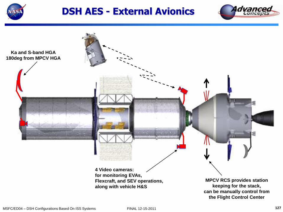
127 MSFC/ED04 – DSH Configurations Based On ISS Systems FINAL 12-15-2011
DSH AES - External Avionics
4 Video cameras:
for monitoring EVAs,
Flexcraft, and SEV operations,
along with vehicle H&S
MPCV RCS provides station
keeping for the stack,
can be manually control from
the Flight Control Center
Ka and S-band HGA
180deg from MPCV HGA

128 MSFC/ED04 – DSH Configurations Based On ISS Systems FINAL 12-15-2011
Sub-System
60-Day 500-Day
Basic
Mass
(kg)
MGA
(%)
Predicted
Mass
(kg)
Basic
Mass
(kg)
MGA
(%)
Predicted
Mass
(kg)
AR&D System 10.8 3.0% 11.2 10.8 3.0% 11.2
Command and Data Handling 219.9 18.3% 260.2 219.9 18.3% 260.2
Displays & Controls 134.0 18.3% 158.5 134.0 18.3% 158.5
Communications System 159.4 18.6% 189.0 187.4 18.1% 221.3
Intercom & Video 55.5 22.2% 67.8 56.4 22.2% 68.9
Instrumentation 45.4 30.0% 58.9 54.4 30.0% 70.7
IHM System 50 10.0% 55.0 70.0 10.0% 77.0
Avionics Cabling 289.7 30.0% 376.6 348.2 30.0% 542.7
Total
964.7 1177.3 1081.2 1320.6
DSH AES – Avionics Mass Summary

129 MSFC/ED04 – DSH Configurations Based On ISS Systems FINAL 12-15-2011
Thermal
Linda Hornsby
December 15, 2011

130 MSFC/ED04 – DSH Configurations Based On ISS Systems FINAL 12-15-2011
Ground Rules & Assumptions
HAT GR&A (tentative)
• Thermal Control
– External fluid loop for heat acquisition using ammonia
– Internal fluid loop for heat acquisition using 60% prop glycol/water
– ~13 kW heat acquired from MM cabin & avionics rejected using ISS-type radiators.
– MLI covering external habitat surface for passive TCS.
– ~13 kW heat acquired from MM cabin & avionics rejected using ISS-type radiators w/ 10 mil Ag-teflon coating
Modifications to GR&A
• Thermal Control
– Active waste heat collection/rejection
• Redundant internal pumped water loop
• Redundant external pumped ammonia loop
• ISS LTL/MTL TCS components (pump package, filters, valves, HX, QDs, etc.)
• ISS External TCS components (pump package, filters, valves, HX, QDs, etc.)
• Deployed, non-articulating ISS PVR radiator.
– Exterior shell thermal control
• 19-layers DAK MLI, Nomex outer layer
• Areal density estimated at .5 kg/m2
• Shell heaters on HAB, MPLM, and tunnel

131 MSFC/ED04 – DSH Configurations Based On ISS Systems FINAL 12-15-2011
DSH Thermal Control System Design Approach
• External TCS System based on ISS design and flight proven through successful mission operations (TRL 9).
• Internal TCS System using ISS flight proven components, removed from racks and redistributed (TRL 8)
• Active waste heat collection – redundant internal and external pumped loops with cold plates and heat exchangers
– DSH 60-Day mission metabolic and equipment waste heat – 11,970 W
– DSH 500-Day mission metabolic and equipment waste heat – 12,925 W
• Active waste heat rejection
– Radiators (with redundant loops) – deployed, non-articulating in flight
• Passive waste heat rejection
– MPLM, HAB, tunnel pressure shell– multi-layer insulation (MLI)
• Exterior temperature control
– MPLM, HAB, tunnel pressure shell– MLI and heaters
– Exterior antennas, cameras, and gimbal shelf– MLI, heaters, louvers, coatings
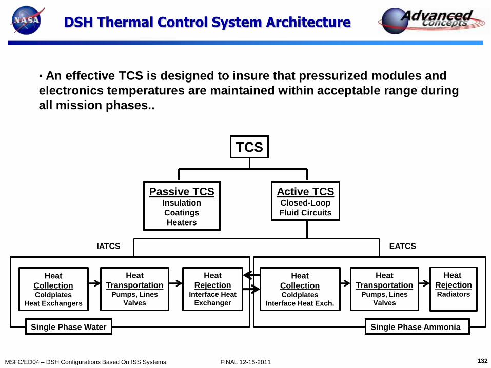
132 MSFC/ED04 – DSH Configurations Based On ISS Systems FINAL 12-15-2011
DSH Thermal Control System Architecture
• An effective TCS is designed to insure that pressurized modules and
electronics temperatures are maintained within acceptable range during
all mission phases..
TCS
Active TCS Closed-Loop
Fluid Circuits
Passive TCS Insulation
Coatings
Heaters
Heat
Collection Coldplates
Heat Exchangers
Heat
Rejection Interface Heat
Exchanger
Heat
Collection Coldplates
Interface Heat Exch.
Heat
Transportation Pumps, Lines
Valves
Heat
Rejection Radiators
Heat
Transportation Pumps, Lines
Valves
Single Phase Water Single Phase Ammonia
EATCS IATCS

133 MSFC/ED04 – DSH Configurations Based On ISS Systems FINAL 12-15-2011
Active Thermal Control Schematic
Active Thermal Control

134 MSFC/ED04 – DSH Configurations Based On ISS Systems FINAL 12-15-2011
DSH Active Thermal Control
Internal Active Thermal Control • Components
-Pump Package Assembly (PPA)
-Coldplates
-Flow Control Valves (FCVs)
-Three-Way Mixing Valves (TWMV)
-Loop Cross-Over Assembly
-Temperature Sensors
•Low Temperature Loop (LTL) -Typically support ECLSS requirements
-Insulated lines, operate below dewpoint
• Moderate Temperature Loop (MTL) •Typically support C&DH, Comm, etc.
•Un-insulated lines, operate above dewpoint
TCS centrally located in
HAB to facilitate line
access to both forward
and aft sections

135 MSFC/ED04 – DSH Configurations Based On ISS Systems FINAL 12-15-2011
DSH Thermal Control Heat Rejection
EEATCS/PVR Radiator ORU Heat
Rejection Capability 7kW -14kW each
Sizing is highly dependent on
environmental heating and radiative
interactions with other spacecraft
surfaces.
Heritage – ISS EEATCS/PVR ORU
Weight - 741 kg each Heat Dissipation to TCS
60/500-Days
Item
Total Heat
Dissipation (W)
C&DH, Instrumentation 1024
Displays & Controls 452
Communications 525/625
Intercom / Video 292
Cabin Lighting 200/240
Circulation Fans 350/450
Heat Transport Pumps 700
Refrigerator/Freezer 540/1080
ECLSS 6373
Metabolic (4 crew) 544
Power Systems 970/1145
Totals 11,970/12,925
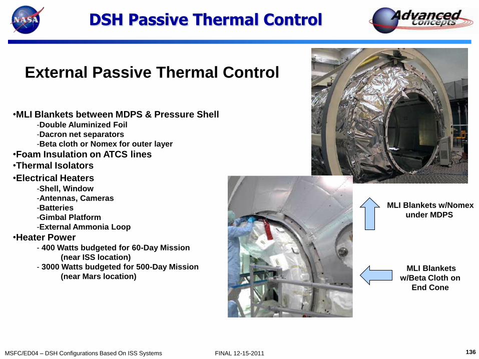
136 MSFC/ED04 – DSH Configurations Based On ISS Systems FINAL 12-15-2011
DSH Passive Thermal Control
External Passive Thermal Control
•MLI Blankets between MDPS & Pressure Shell -Double Aluminized Foil
-Dacron net separators
-Beta cloth or Nomex for outer layer
•Foam Insulation on ATCS lines
•Thermal Isolators
•Electrical Heaters -Shell, Window
-Antennas, Cameras
-Batteries
-Gimbal Platform
-External Ammonia Loop
•Heater Power - 400 Watts budgeted for 60-Day Mission
(near ISS location)
- 3000 Watts budgeted for 500-Day Mission
(near Mars location)
MLI Blankets w/Nomex
under MDPS
MLI Blankets
w/Beta Cloth on
End Cone

137 MSFC/ED04 – DSH Configurations Based On ISS Systems FINAL 12-15-2011
Thermal Mass Comparison by Mission
Subsystem
60-Day 500-Day
Basic
Mass
(kg)
MGA
(%)
Predicted
Mass
(kg)
Basic
Mass
(kg)
MGA
(%)
Predicted
Mass
(kg)
Internal TCS Rack LT/MT 226 20 271 226 20 271
Internal Rack Support 270 20 324 300 20 360
Internal TCS Misc. 30 30 39 30 30 39
External Active TCS 376 15 432 376 15 432
External Passive TCS 155 20 187 199 20 239
External Heat Rejection Sys. 1482 3 1526 1482 3 1526
Total 2539 2780 2613 2868
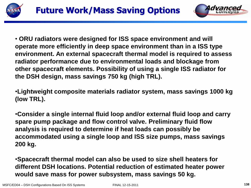
138 MSFC/ED04 – DSH Configurations Based On ISS Systems FINAL 12-15-2011
Future Work/Mass Saving Options
• ORU radiators were designed for ISS space environment and will
operate more efficiently in deep space environment than in a ISS type
environment. An external spacecraft thermal model is required to assess
radiator performance due to environmental loads and blockage from
other spacecraft elements. Possibility of using a single ISS radiator for
the DSH design, mass savings 750 kg (high TRL).
•Lightweight composite materials radiator system, mass savings 1000 kg
(low TRL).
•Consider a single internal fluid loop and/or external fluid loop and carry
spare pump package and flow control valve. Preliminary fluid flow
analysis is required to determine if heat loads can possibly be
accommodated using a single loop and ISS size pumps, mass savings
200 kg.
•Spacecraft thermal model can also be used to size shell heaters for
different DSH locations. Potential reduction of estimated heater power
would save mass for power subsystem, mass savings 50 kg.
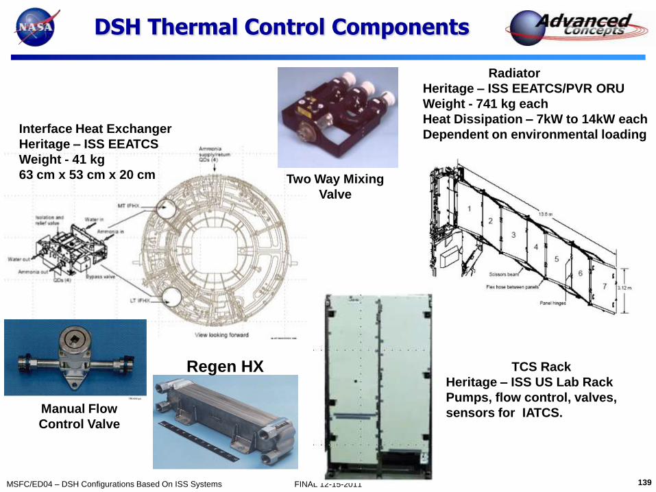
139 MSFC/ED04 – DSH Configurations Based On ISS Systems FINAL 12-15-2011
DSH Thermal Control Components
Radiator
Heritage – ISS EEATCS/PVR ORU
Weight - 741 kg each
Heat Dissipation – 7kW to 14kW each
Dependent on environmental loading Interface Heat Exchanger
Heritage – ISS EEATCS
Weight - 41 kg
63 cm x 53 cm x 20 cm
TCS Rack
Heritage – ISS US Lab Rack
Pumps, flow control, valves,
sensors for IATCS.
Regen HX
Two Way Mixing
Valve
Manual Flow
Control Valve

140 MSFC/ED04 – DSH Configurations Based On ISS Systems FINAL 12-15-2011
Environments Protection
Tiffany E. Russell
December 15, 2011
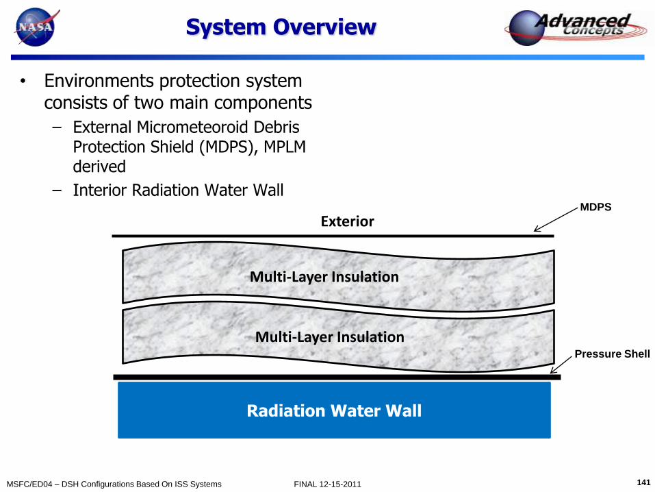
141 MSFC/ED04 – DSH Configurations Based On ISS Systems FINAL 12-15-2011
System Overview
• Environments protection system consists of two main components
– External Micrometeoroid Debris Protection Shield (MDPS), MPLM derived
– Interior Radiation Water Wall
Multi-Layer Insulation
Multi-Layer Insulation
Exterior
Radiation Water Wall
Pressure Shell
MDPS

142 MSFC/ED04 – DSH Configurations Based On ISS Systems FINAL 12-15-2011
Crew Quarters Protection
• Nominal 60 and 500 day case, water wall
– 0.55 cm thick polyethylene tank
– 9.9 cm thick water wall
– Total protection = 11 g/cm2
– Mass = 2850 kg
• Water wall provides a storm shelter during a Solar Particle Event (SPE)
– Current design does not include protection against Galactic Cosmic Radiation (GCR)
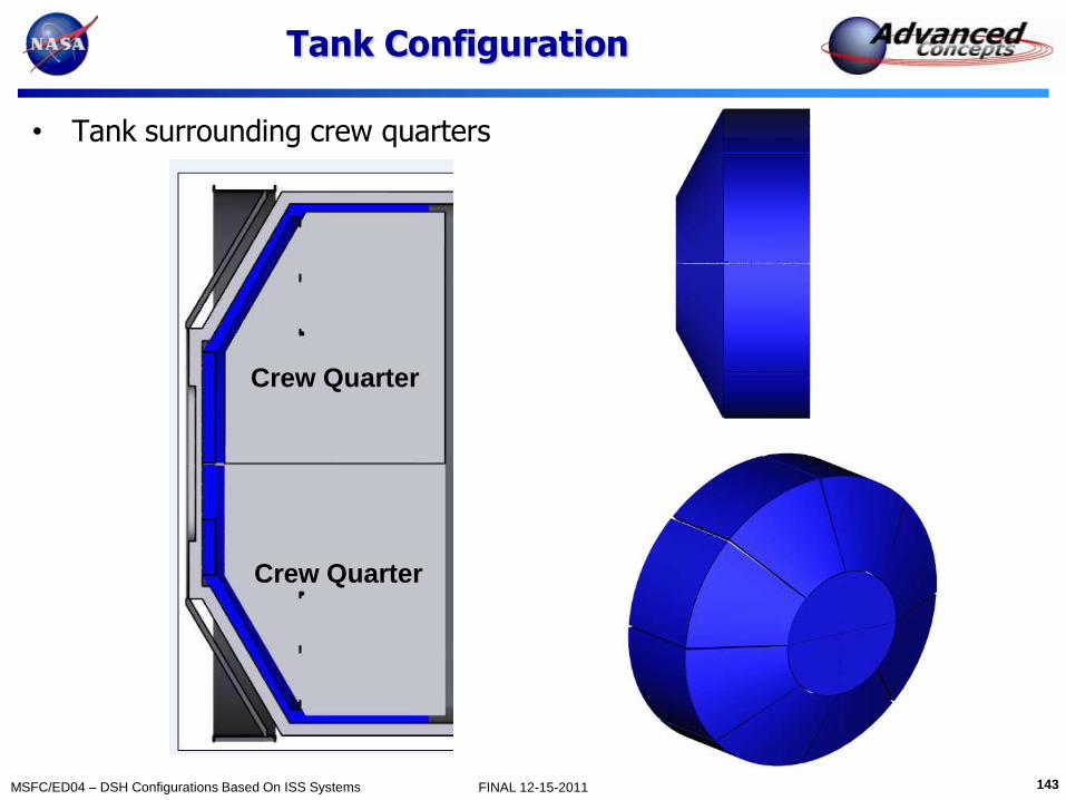
143 MSFC/ED04 – DSH Configurations Based On ISS Systems FINAL 12-15-2011
Tank Configuration
• Tank surrounding crew quarters
Crew Quarter
Crew Quarter

144 MSFC/ED04 – DSH Configurations Based On ISS Systems FINAL 12-15-2011
Tank Configuration
• End Cap Segments • Crew Quarters Segments
1
2
3
4 5
6
8
7
9
1
2
4
3

145 MSFC/ED04 – DSH Configurations Based On ISS Systems FINAL 12-15-2011
Mass Savings
• Dual functioning water tanks
– Water transported on DSH can be used for radiation protection and ECLSS
• ECLSS H2O will bring 504 kg for 60 day and 1440 kg for 500 day
• 60 day mission requires 9.9 cm water wall of protection
• Use food and storage as a shield
• Design storage bags with radiation shielding materials (e.g. polyethylene)
• Replace depleted water tanks with waste water and brine
− Brine available every 30 days
− Refill storage with generated refuse
60 day (kg) 500 day (kg)
MDPS 1121 1713
ECLSS 504 1440
Radiation Water Wall 2850 2850
Dual Water Storage System 2346* 1410*
*These numbers do not include the amount of water produced by ECLSS through out the duration of the mission

146 MSFC/ED04 – DSH Configurations Based On ISS Systems FINAL 12-15-2011
Mass Summary
Sub-System
60 Day 500 Day
Basic
Mass
(kg)
MGA
(%)
Predicted
Mass
(kg)
Basic
Mass
(kg)
MGA
(%)
Predicted
Mass
(kg)
Micro-Meteoroid & Debris
Protection System (MPDS) 1121 10 1233 1713 10 1884
Radiation Protection Tank 332 5 349 332 5 349
Radiation Water 2518 3 2594 2518 3 2594
Total 3971 4176 4563 4827

147 MSFC/ED04 – DSH Configurations Based On ISS Systems FINAL 12-15-2011
Mass Savings
• Reconfigure the internal layout for 500 day mission
– Fill end-cap with wet storage and 4 ECLSS water racks to provide a 25% water mass reduction
– An additional water wall will need to be added to the wall adjacent to the ward room
Crew
Quarters
Crew
Quarters
Ward Room
Rack
Rack
Rack
Rack
Rack
Rack
Permanent Water Wall
Permanent Water Wall
Permanent Water Wall
Storage
2 ECLSS Water Racks
2 ECLSS Water Racks
148 MSFC/ED04 – DSH Configurations Based On ISS Systems FINAL 12-15-2011
Attached Vehicles
David Smitherman
December 15, 2011

149 MSFC/ED04 – DSH Configurations Based On ISS Systems FINAL 12-15-2011
Notional MPCV* Element Description
The MPCV provides crew ascent, entry, and on-orbit support including aborts. It is based on an Orion crew module, service module, and launch abort system. The MPCV carries the crew to LEO, providing ascent abort coverage. It is the active crewed element during the trip from LEO to Earth-Moon L1. It has sufficient delta V to return the crew from L1 in an abort scenario. The MPCV is in a quiescent mode during the trip from L1 to a NEO and during most of the return trip. The MPCV provides EDL to a water landing.
Design Constraints/Parameters
Pressurized volume 19.6 m3
Habitable volume 9.3 m3
Crew size 3-4
Active crewed duration 21.1 days
Quiescent duration 400 days
Main propulsion 1 OME, 33400 N, Isp = 326 s
Auxiliary propulsion 8 R-4D, 490 N, Isp = 308 s
RCS 16 R-1E, 111 N, Isp = 275 s
Delta V requirement 1453 m/s
Propellant tank capacity 8602 kg
Power, uncrewed 2576 W
Power, crewed 3261 W
Solar power generation 10.8 kW max
Total battery energy storage 12608 W-hr
Entry speed < 11.8 km/s
Description
*Analysis anchored to above data with small variances to accommodate differences in consumables and crew
Assumed Design Parameters

150 MSFC/ED04 – DSH Configurations Based On ISS Systems FINAL 12-15-2011
FlexCraft* is a single-person spacecraft designed for servicing /exploration of ISS, NEOs and satellites. It can be piloted or tele-operated. Using the same atmosphere as the host vehicle provides immediate access to space without pre-breathing or airlock. Integral propulsion enables rapid translation to the work site. It is sized for all crew working shirt sleeve operating conventional displays and controls.
Design Constraints/Parameters
Pressurized Vol. 0.62 m3
Crew Size 1
Excursion time < 8hrs
Atmosphere O2/N2 same as host
Pre-breathe None
Operations Shirt sleeve
Design Population One size fits all
Control Piloted or tele-op
Equip/sample bin 1
Propellant GN2 (rechargeable)
Delta-v 21 m/s
Battery energy stor 2700 W-h
ECLSS Repackaged PLSS
Thermal Control SWME
Radiation Protection
No excursions during SPE (mission specific Polyethylene liner)
Category Mass (kg)
121
Propulsion 51
42
Avionics 40
21
44
20
GROWTH 41
DRY MASS 379
1
58
INERT MASS 437
Total Less Propellant 437
14
TOTAL GROSS MASS 452
Propellant
Thermal
ECLSS
Docking Mechanism
Non-Prop Fluids
Manipulators
Structures
Power
Description
08-29-2011
* FlexCraft POC is Brand Griffin/ED04 Advanced Concepts Office
FlexCraft
151 MSFC/ED04 – DSH Configurations Based On ISS Systems FINAL 12-15-2011
Vehicle Sizing References
David Smitherman
December 15, 2011

152 MSFC/ED04 – DSH Configurations Based On ISS Systems FINAL 12-15-2011
ISS Module Internal Volumes
MPLM volume (similar to
Columbus module and
Nodes 2 & 3) • Pressurized: 76.4 m3
• Habitable: 32.3 m3
HAB volume (similar to
US Lab) • Pressurized: 111.51 m3
• Habitable: 34.77 m3
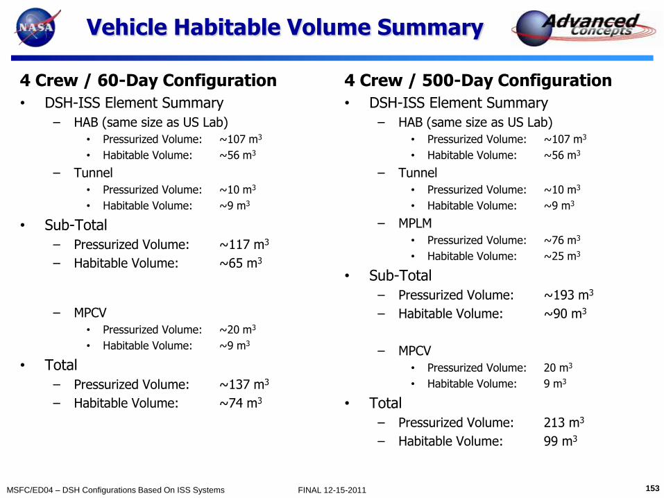
153 MSFC/ED04 – DSH Configurations Based On ISS Systems FINAL 12-15-2011
Vehicle Habitable Volume Summary
4 Crew / 60-Day Configuration
• DSH-ISS Element Summary
– HAB (same size as US Lab)
• Pressurized Volume: ~107 m3
• Habitable Volume: ~56 m3
– Tunnel
• Pressurized Volume: ~10 m3
• Habitable Volume: ~9 m3
• Sub-Total
– Pressurized Volume: ~117 m3
– Habitable Volume: ~65 m3
– MPCV
• Pressurized Volume: ~20 m3
• Habitable Volume: ~9 m3
• Total
– Pressurized Volume: ~137 m3
– Habitable Volume: ~74 m3
4 Crew / 500-Day Configuration
• DSH-ISS Element Summary
– HAB (same size as US Lab)
• Pressurized Volume: ~107 m3
• Habitable Volume: ~56 m3
– Tunnel
• Pressurized Volume: ~10 m3
• Habitable Volume: ~9 m3
– MPLM
• Pressurized Volume: ~76 m3
• Habitable Volume: ~25 m3
• Sub-Total
– Pressurized Volume: ~193 m3
– Habitable Volume: ~90 m3
– MPCV
• Pressurized Volume: 20 m3
• Habitable Volume: 9 m3
• Total
– Pressurized Volume: 213 m3
– Habitable Volume: 99 m3

154 MSFC/ED04 – DSH Configurations Based On ISS Systems FINAL 12-15-2011
4 Crew / 60-Day case EXAMINE Tool
Reference sizing from the EXAMINE tool by LaRC/Matt Simon

155 MSFC/ED04 – DSH Configurations Based On ISS Systems FINAL 12-15-2011
4 Crew / 500-Day case EXAMINE Tool
Reference sizing from the EXAMINE tool by LaRC/Matt Simon