DE - Lamp Tech
28
tAU DE
Transcript of DE - Lamp Tech
tAU DE
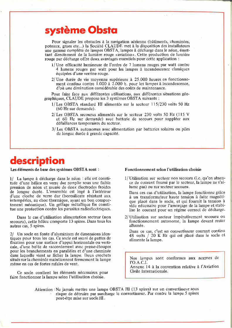
système ObstqPour signaler les obstacles à la navigation aérienne (bâtiments, cheminées;
poteaux, grues etc...) la Société CLAUDE met à la disposition des installateursune gamme complète de lampes OBSTA,lampes à décharge dans le néon, émet-tant directement de la lumière rouge <aviation>. Cette production de lumièrerouge par décharge offre deux avantages essentiels pour cette application :
1/Une efficacité lumineuse de l'ordre de T lumens rouges par watt contre4 lumens rouges par watt pour les lampes à incandescence classiqueséquipées d'une verrine rouge.
2lUne durée de vie moyenne supérieure à 25.000 heures en fonctionne-ment continu contre 1.000 à 2.000 h. pour les lampes à incandescence,d'où une diminution considérable des coûts de maintenance.
Pour faire face aux différentes utilisations, aux différentes situations géo-graphiques, CLAUDE propose les 3 systèmes OBSTA suivants :
1/Les OBSTA standard HI alimentés sur le secteur ll5l230 volts 50 Hz(60 Hz sur demande).
2lLes OBSTA secourus alimentés sur le secteur 230 volts 50 Hz (l15 Vet 60 Hz sur demande) avec batterie de secours pour suppléer auxdéfaillances temporaires du secteur.
3/ Les OBSTA autonomes avec alimentation par batteries solaires ou pilesde longue durée à grande capacité.
descriptionIæs éléments de base des systèmes OBSTA sont :
I I La lampe à décharge dans le néon : elle est consti-tuée d'une hélice en verre dur remplie sous une faiblepression de néon et munie de deux électrodes froidesde longue durée. L'ensemble est logé à l'intérieurd'une cloche de verre dur (borosilicate résistant auxintempéries, au choc thermique, ayant un bon compor-tement mécanique). Un grillage métallique fin consti-tue une protection contre les parasites radioélectriques.
Dans le cas d'utilisation alimentation secteur (nonsecouru), cette hélice comporte 13 spires. Dans tous lesautres cas, 5 spires.
2l Un socle en fonte d'aluminium de dimensions iden-tiques pour tous les cas. Ce socle est muni de pattes defixation pour une surface d'appui horizontale ou verti-cale, d'une boîte de raccordement avec presse-étoupespour les branchements en parallèles et d'une cheminéedans laquelle vient se ficher la lampe. Deux crochetssitués surla cheminée maintiennent fermement la lampemême en cas de fortes rafales de vent.
Ce socle contient les éléments nécessaires pourfaire fonctionner la lampe selon I'utilisation choisie.
Fonctionnement selon I'utilisation choisie
1/ Utilisation sur secteur non secouru (i.c. qu'en absen-ce de courant fourni par le secteur, la lampe ne s'ai-lume pas) ou sur secteur secouru.
Dans ces cas d'utilisation, la lampe fonctionne grâceà un transformateur haute tension à fuite magnétique placé dans le socle, et qui fournit la tension àvide nécessaire pour I'amorçage de la lampe et stabi-lise le courant pour un régime correct de décharge.
2/ Utilisation sur secteur impérativement secouru oufonctionnement autonome, la lampe devant resterallumée.
Dans ce cas, c'est un convertisseur courant continu48 volts I 20 K Hz qui est placé dans le socle etalimente la lampe.
Nos lampes sont conformes aux normes deI'O.A.C.I.Annexe 14 à la convention relative à I'AviationCivile lnternationale.
Attention :Ne jamais mettre une lampe OBSTA HI (13 spires) sur un convertisseursousrisque de détruire par surcharge le convertisseur. Par contre la lampe 5 spirespeut€t1e mise sur socleHI.
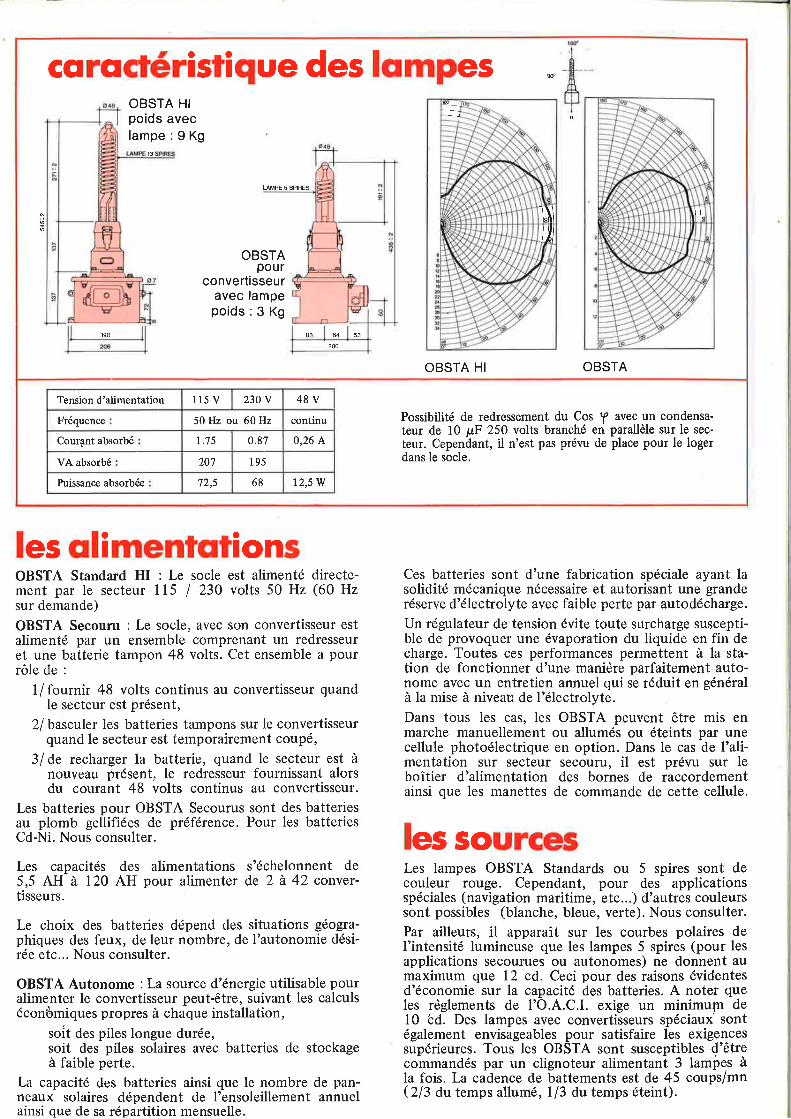
cqrqctéristique des lompesOBSTA HIpoids aveclampe : 9 Kg
13
UMPE 5 SPIRES
OBSTApour
convertisseuravec lampepoids : 3 Kg
190 a3 64 53
OBSTA HI OBSTA
200
----j
T-\\
t/lt
t\,
Possibilité de redressement du Cos f avec un condensa'teur de 10 pF 250 volts branché en parallèle sur le sec-
teur. Cependant, il n'est pæ prévu de place pour le logerdans le socle.
Tension d'alimentation 115 V 230 V 48V
Fréquence 50 Hz ou 60 Hz continu
Courant absorbé r.'15 0.87 0,26 A
VA absorbé 20'1 195
Puissance absorbée 72,s 68 12,5 W
les qlimentqtionsOBSTA Standard HI : Le socle est alimenté directe-ment par le secteur I 15 / 230 volts 50 Hz (60 Hzsur demande)
OBSTA Secouru : Le socle, avec son convertisseur estalimenté par un ensemble comprenant un redresseuret une batterie tampon 48 volts. Cet ensemble a pourrôle de :
1/fournir 48 volts continus au convertisseur quandle secteur est présent,
2/ basculer les batteries tampons sur le convertisseurquand le secteur est temporairement coupé,
3/ de recharger la batterie, quand le secteur est ànouveau présent, le redresseur fournissant alorsdu courant 48 volts continus au convertisseur.
Les batteries pour OBSTA Secourus sont des batteriesau plomb gellifiées de préférence. Pour les batteriesCd-Ni. Nous consulter.
Les capacités des alimentations s'échelonnent de5,5 AH à 120 AH pour alimenter de 2 à 42 convertisseurs.
Le choix des batteries dépend des situations géogra-phiques des feux, de leur nombte, de I'autonomie dési-rée etc... Nous consulter.
OBSTA Autonome :La source d'énergie utilisable pouralimenter le convertisseur peut-être, suivant les calculséconùmiques propres à chaque installation,
soit des piles longue durée,soit des piles solaires avec batteries de stockageà faible perte.
La capacité des batteries ainsi que le nombre de pan-neaux solaires dépendent de I'ensoleillement annuelainsi que de sa répartition mensuelle.
Ces batteries sont d'une fabrication spéciale ayant lasolidité mécanique nécessaire et autorisant une granderéserve d'électrolyte avec faible perte par autodécharge.
Un régulateur de tension évite toute surcharge suscepti-ble de provoquer une évaporation du liquide en fin decharge. Toutes ces performances permettent à la sta-tion de fonctionner d'une manière parfaitement auto-nome avec un entretien annuel qui se réduit en généralà la mise à niveau de l'électrolyte.Dans tous les cas, les OBSTA peuvent être mis enmarche manuellement ou allumés ou éteints par unecellule photoélectrique en option. Dans le cas de I'ali-mentation sur secteur secouru, il est prévu sur leboîtier d'alimentation des bornes de raccordementainsi que les manettes de commande de cette cellule.
les sourcesLes lampes OBSTA Standards ou 5 spires sont decouleur rouge. Cependant, pour des applicationsspéciales (navigation maritime, etc...) d'autres couleurssont possibles (blanche, bleue, verte). Nous consulter.Par ailleurs, il apparaît sur les courbes polaires del'intensité lumineuse que les lampes 5 spires (pour lesapplications secourues ou autonomes) ne donnent aumaximum que 12 cd. Ceci pour des raisons évidentesd'économie sur la capacité des batteries. A noter queles règlements de I'O.A.C.I. exige un minimuln del0 bd. Des lampes avec convertisseurs spéciaux sontégalement envisageables pour satisfaire les exigencessupérieures. Tous les OBSTA sont susceptibles d'êtrecommandés par un clignoteur alimentant 3 lampes àla fois. La cadence de battements est de 45 coups/mnQB au temps allumé, l/3 dutemps éteint).

NN
IÉU
zI
o\oal
\o&
Département Applications Professionnelles
r alllngolohstacles$gn
toaulatlon
f
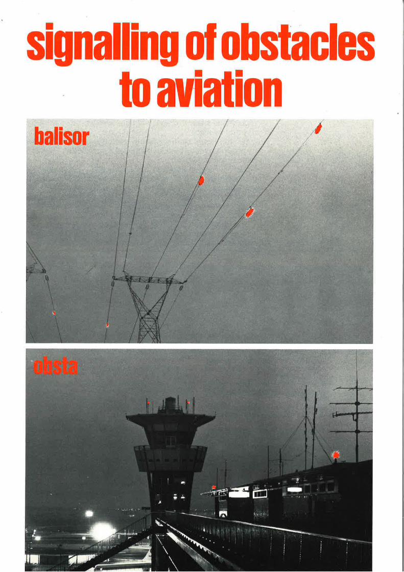
balisorThe development of air traffic necessitates increased
safety measures for aircraft, particularly in the vicinity ofairports.
ln view of this fact, many countries have adopted regulationslaying down measures to be taken and, in particular, makingit compulsory for any obstacles which might constitute adanger in such areas to be indicated by warning signals.
Sections of electric power lines which are subject to theseregulations have to carry warning signals visible both byday and by night.
For the hours of daylight the lines are rendered visibleby attaching metal balls to them, but the problem of lightingthem at night remains.
The H.T. lines in question are usually distant from centresof population, so that there can be no question of using LT.for lighting them, and there are considerable difficultiesabout transforming the HJ. current locally; a simple solutionto the problem was discovered by CLAUDE as far backas 1937, using the "BALISOR" lighting device.
The "BALISOR-CLAUDE" device is merely a simple andeconomic means of taking the small amount of powerrequired direct from the H.T lines to be illuminated.
operating principleA power line sets up around itself an electro-
static field. ln the case of alternating current, if weplace near it an insulated auxiliary line, there is adifference of potential between the main andauxiliary lines capable of supplying a judiciouslyselected source of light.
the source of lightThe "BALISOR" lamp is designed to function at
the high tensions of several thousands volts bet-ween the principal and auxiliary lines. lt consistsof a tube discharging into a neon atmosphere andhas the following advantages:o gredt flexibility as regards the supply voltage,o negligible consumption owing to its high degreeof luminous efficacity,. can be worked into any shape required: the tubeis in spiral form so as to increase the intensity oflight emitted,o it gives a red light (neon luminescence), which isthe colour normally used as a sign of danger. ltslong expectation of life, which is characteristic ofneon tubes, renders it adaptable to the safetyconditions governing the operation of power lines.
description of the balisor lampThis consists of a neon tube 7 mm (aboulO.27")
in diameter, rolled into a spiral, fitted with two coldelectrodes and mounted in a protective tubeclosed at each end by a metal plug.
The whole is housed in a cylindrical pyrexcontainer, of 50 mm (about 2") external diameter,which is filled with a liquid absorbing both shocksand radio interferences.
The two plugs are sealed so as to render themimpervious to the liquid, and each contains a resis-tance in series with the lamp to stabilize the dis-charge, and prevent high frequency radiations.Thelamp is suspended from the principal and auxiliarylines by two flexible connectors, which absorb theshock of any vibrations in the lines themselves.Thus protected, the lamp has excellent propertiesof mechanical resistance.
auxiliary lineThe difference of potentialbetween the principal
and auxiliary lines should be sufficient to start thelamp.
Moreover, for a given tension between the princi-pal line and earth, there is a linear relation betweenthe capacity of the auxiliary line and the strengthof current passing through the light, and thus thebrilliancy emitted.
Lastly, to attain a given degree of brilliancy, thelength of auxiliary line required is in inverse propor-tion to the tension of the principal line.
The "CLAUDE" type of auxiliary line, the efficacityof which has been confirmed in numerous caseswhere it has been installed, consists of one or moretubular conductor elements of treated aluminium,each 4 meters (about 13 feet) long.
These elements are joined together and attachedto collars clamped on the principal line by means ofinsulators.
The following table shows the number of elementsand accessories required for a minimum brillianceof 10 candle-power at the various line voltagesgenerally used.
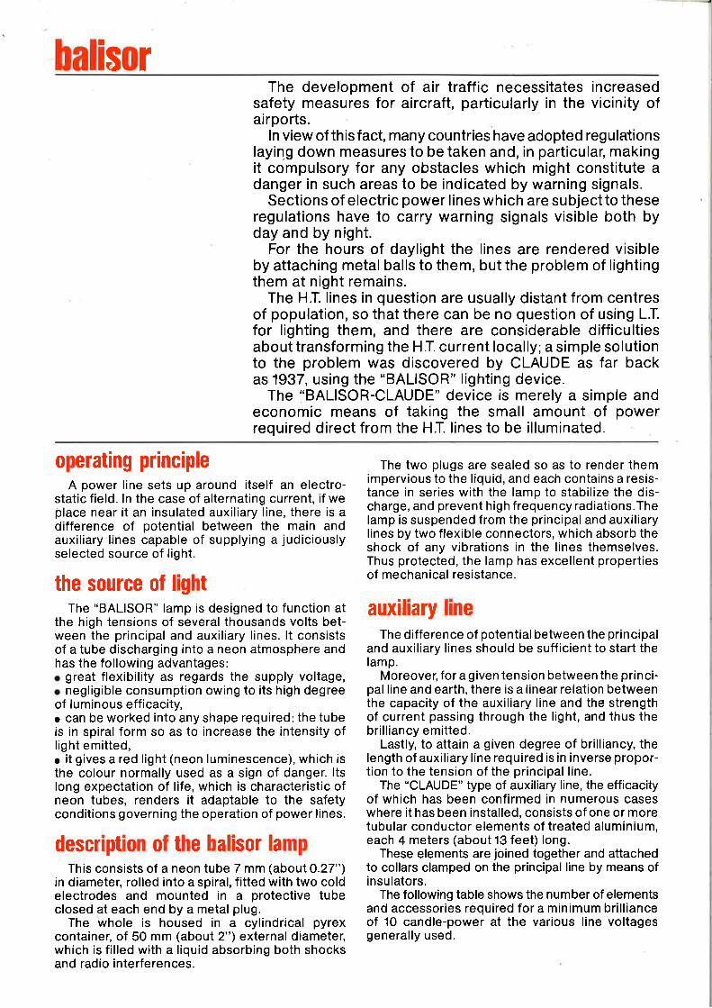
Gomposition of balisor units for different voltagesdescription number of parts according to tension (kV)
60 90 150 220 380weightof part(kg)
BALISOR HIG or N3G LAMP.
END BRACKET
FLEXIBLE CONNECTOR
CAPACITANCE ELEMENT
INSULATOR WITH COLLARS
COLLAR LINERS
BALISOR 380 LAMP
BEARING SWINGLE BAR 380 KV
END SWINGLE BAR 380 KV
EQUIPED INSULATOR 380 KV
CAPACITANCE ELEMENT 380 KV
GRIPPING-JAWS (for brace A 32)
GASKET 380 KV
1
1
2
7
8
17
1
1
2
4
5
11
1
2
1
3
1
3
1
1
2
2
4
2
4
1
1
2
2
3
7
3.100
0.250
0.650
1 .100
2.350
4.100
2.140
1.560
1.800
0.670
2.000
0.200
NB.:When placing an order, please indicate the diameter of the wire
"BALISOR" references:French civil and military airportso ORLYo LE BOURGETr ROISSY-EN-FRANCEo MARSEILLE
All over the worldo EUROPEo EAST EUROPEo AFRICAo LATIN AMERICA
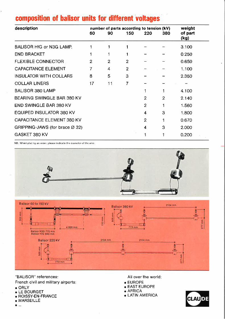
obstaApart from power lines, the obstacles covered
by aviation safety regulations include buildings ofabove what is considered a dangerous height, suchas factory chimneys, pylons, water towers, etc.,all of which have to be fitted with warning lights.
Such buildings are to be found in the vicinity of alow tension supply, to which the warning lights caneasily be connected.
Forthis purpose, CLAUDE has devised awarninglight based on the principle of discharge tubes.This is known as "OBSTA'i and since it has a longlife, maintenance is reduced to a minimum-animportant consideration with devices which are noteasily accessible.
The "OBSTA" consists of :
o a combined junction box and transformer housedin a watertight casing fitted to the pole or pylon.The junction box is threeway and incorporates a
fuse. The secondary winding of the transformerprovides the current for the special lamp, while theprimary may be fed either with 110 or 220 volts.o a red (neon), green, white or blue (fluorescence)lamp consisting of a discharge tube in spiral formcontained in a glass protecting sleeve, and with aplug at one end for fixing the lamp to the junction box.
Red "OBSTA" lamps are fitted with a deviceacting as a Faraday cage to protect them againststatic discharges. The device is fitted inside theglass containing the spiral tube.
Consumption:69 W.Weight of complete unit: 6.75 kg (14 lb 12 oz).
For OBSTA Lamp delivering "flickering light",p/ease consu/t us.
O
o
206 mm
EENo6
2o0 mm
.
''l
@7mm
EENts
190 mm
6.8 -t
r'a
Claude soci6t6 anonymeau capital de 30.497.670 F
siege social . 27,29, rue de Sevres921 03 Bou logne-B illancourttel. : 604 91 84 - telex 26080
B.P 406 - R.C. Paris 55 B 10925
the Obstq systemContributing to safety in civil air traffic CLAUDE supplies a whole range
of beacons for signalling obstacles in the flight path.The main common feature of these beacons is a neon discharge lamp, giving outdirectly aviation red light. This red discharge light has two basic advantagesnamely :
1/Luminous efficiency of about 7 rcd lumens per watt compared with4 red lumens per watt for classic incandescent lamps equipped with redfilter.
2l Average life of more than 25.000 hours continuous operation as against1.000 to 2.000 hours for incandescent lamps, hence a considerabledecrease in maintenance cost.
In order to meet different utilisations in various geographical situationsCLAUDE suggests the following 3 OBSTA systems :
l/The Standard HI OBSTA powered by the mains 1l5l23} Volts 50 Hz(60 Hz upon request).
2/ OBSTA models wilh built-in reserve powered by the mains I l5/230 Volts50 Hz (115 V 6O Hz upon request) with a buffer battery to take overtemporary mains failures.
3/ Autonomous OBSTA powered by Solar panels or long life, high capacitychemical batteries.
descriptionThe basic elements of OBSTA systems are :
I I A neon discharge lamp : it is composed of a heavyduty, hard glass helicoidal low pressure discharge tubeequipped with two long life cold cathodes. All this ismounted within a hard glass outer sleeve (Borosilicateglass withstanding bad weather, thermal shocks andmechanical stress). A fine metal mesh guards againstRF perturbations.
In the case of mains supply (without energyreserve) this tube is composed of l3 turns. In all othercases 5 turns.
2l A base in aluminium cast of the same dimensionsfor every case. This base is fixed to horizontal orvertical supporting surfaces by means of anchorflanges.
There is a connecting box with watertight seal forparallel connexions of several units.
There is also a chimney-shaped lamp-holder. Onescrew on the side of the chimney maintains the lampfirmly in position even in case of strong gusts of wind.
This base houses the necessary elements to operatethe lamp.
LAMP OPERATION.
ll Utilisation on the mains, without power reserye(i.e. in case of mains failure the lamp does not light)or on the mains with auxiliary generator.
This transformer supplies the proper open voltageto ensure the striking of the discharge and stabilizesthe current for a correct discharge value.
2l Utilisation on mains, or operating autonomously,when the lamp must in no account stop lighting :
In this case a converter D.C.48V120 kHz is placedin the base and powers the lamp.
Our beacons fulfill the requirements & re-commendations issued by the ICAO.
Annex 14 to the Convention relative to theInternational Civil Aviation.
Caution : Never overload the DC-AC convetter by matching a high power consumingl3 turn HI lamp onto it.On the contrary a 5 turn low power lamp may be.perfectly matched to thestandard HI transformer.
rd
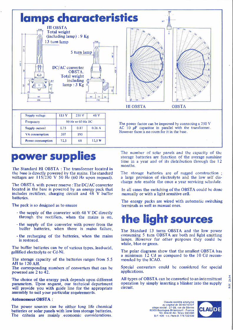
lqmps chqrqcteristics #fiHI OBSTA
Total weight(includinglamp):9Kg
13 turn lamp
5 turn lamp
DC/AC converterOBSTA.
Total weightincluding
lamp :3 Kg
r90 64 53
HI OBSTA OBSTA
2@
(3
o
I[\til
il\,
The power factor can be improved by connectinga2SOYAC l0 pF capacitor in parallel with the transformer.However there is no room for it in the base.
Supply voltage 115 V 230 V 48V
Frequency 50 Hz or 60 Hz DC
Supply current 1.7 5 0.87 0.26 A,
VA consumption 207 195
Power consumption 7 2,5 68 12.5 W
power suppliesThe Standard HI OBSTA : The transformer located inthe base is directly powered by the mains. The standardvoltages are I l5l23O V 50 Hz (60 Hz upon request).
The OBSTA with power reserve :The DC/AC converterlocated in the base is powered by an energy pack thatincludes rectifiers, charging circuit and 48 V bufferbatteries.
The pack is so designed as to ensure
- the supply of the converter with 48 V DC directlythrough the rectifiers, when the mains is on,
- the supply of the converter with power from thebuffer batteries, when there is mains failure,
- the recharging of the batteries, when the mainsis restored.
The buffer batteries can be of various types,lead-acid,gellified electrolyte or Cd-Ni.
The storage capacity of the batteries ranges from 5.5AH to 120 AH.The corresponding numbers of converters that can bepowered are 2 to 42.
The choice of the energy pack depends upon differentparameters. Upon request, our technical departmentwill provide you with guide line for the appropriateassembly to suit your particular requirements.
Autonomous OBSTA :
The power sources can be either long life chemicalbatteries or solar panels with low loss storage batteries.The criteria are mainly .economic considerations.
The number of solar panels and the capacity of thestorage batteries are function of the average sunshinetime in a year and of its distribution through the 12months.
The storage batteries are of rugged construction ;
a large provision of electrolyte and the low self dis-charge rate enable the once a year servicing schedule.
In all cases the switching of the OBSTA could be donemanually or with a light sensitive cell.
The energy packs are wired with automatic switchingterminals as well as manual ones.
the light sourcesThe Standard 13 turns OBSTA and the low powerconsuming 5 turn OBSTA are both red light emittinglamps. However for other purposes they could bewhite, blue or green.
The polar diagrams show that the smallest OBSTA hasa minimum 12 Cd as compared to the l0 Cd recom-mended by the ICAO.
Special converters could be considered for specialapplications.
All types of OBSTA can be converted to an intermittentoperation by simply inserting a blinker into the supplycircuit.
Claude societe anonymeau capital de 30497670 F
sidge social : 27-29, rue de Sevres92103 Boulogne-Billancourt - France
Tel. 604.91.84 -Telex 260086B.P 406 - rc. Paris B 775722036
sloNi&
CONVERTISSEURSHI
HI OBSrACONVERTERS
Nous disposons dds i prdsent de convertisseurs pluspuissants pour lampes Obsta HI et HIG. Ils sontdestinds au cas of une intensitd lumineuse supdrieured 35 Cd est exigde avec une alimentation secourue.
La consommation dlectrique est de 50 Watts. L'en-combrement est identique d celui de I'Obsta HIsecteur avec un poids restant pratiquement dL 3 Kg.
Les batteries de stockage d'dnergie doivent avoir unecapacitd de 10 AH par lampe d secourir pour assurertoujours une autonomie de 10 heures.
Ainsi :
l'ensemble d'dnergie 48V 10 AH peut alimenter 3 ou4 Obsta avec convertisseurs normaux ou I Obsta avecconvertisseur HI
l'armoire d'dnergie 48V 20 AH permet d'alimenter7 Obsta convertisseurs normaux ou 2 Obsta conver-tisseurs HI
I'armoire d'dnergie 48V 36 AH permet d'alimenterl2 Obsta convertisseurs normaux ou 3 Obsta conver-tisseurs HI.
Up to now, people who require beacons with lightintensity higher than the l0 red light candelas provi-ded by regular Obsta converters have to use the HVtransformer HI Obstas which operate on the mains(ttsl23AV 50Hzl60Hz).
Without the possibility of a stand by D.C. powersupply for emergency.
We are now in a position to supply our customerswith HI converters that operate the High Intensityl3 glass turn HI Obsta lamps ;The power consumption is 50 W. Dimensions are thesame as regular HI Obstas. Lamp and HI convertertogether weight approximately 3 Kg. operating voltage is 48V DCo battery storage capacity must equal l0 AH per
converter
So our :
l0 AH power pack mWatt converters or I 50
ayw
20 AH cabinet may operate 7 regular 12Watt conver-ters or 2 50W HI converter
36 AH cabinet may operate 12 regular 12 Wattconverters or 314 50W HI converter.
operate 3 or 4 regtlar 12HI converter
Division Gomposants
CLAUDE soci6t6 anonyme au capital de 30 497 670 F - siege social 27-2g. rue de Sevres92103 Boulogne-Brllancourt - Tel. . 604.91.84 - T6lex 260 086Boite postale 40tj - R.C. Paris B 775 722036The Claude Component Oivision reserves all right to modify its produds at any lime for improvom6nt purposes,

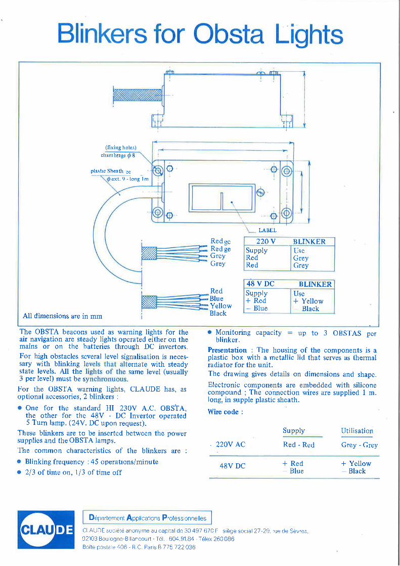
linkers for Obsta Lights
(fixing holes)
chambrage 8
plastic Sheath ss
ext.9-longlm
LABEL
RedgeRed geGreyGrey
All dimensions are in mm
RedBlueYellowBlack
q +I
q +22A V BLINKER
SupplyRedRed
useGreyGrey
48VDC BLINKERSupplv* Red
- Blue
Use* Yellow- Black
The OBSTA beacons used as warning lights for theair navigation are steady lights operated either on themains or on the batteries through DC invertors.For high obstacles several level signalisation is neces-sary with blinking levels that alternate with steadystate levels. All the lights of the same level (usually3 per level) must be synchronuous.
For the OBSTA warning lights, CLAUDE has, as
optional accessories, 2 blinkers :
o One for the standard HI 230V A.C. OBSTA,the other for the 48V - DC Invertor operated5 T'urn lamp. (24Y. DC upon request).
These blinkers are to be inserted between the powersupplies and the OBSTA lamps.
The common characteristics of the blinkers are :
o Blinking frequency :45 operatrons/minuteo 213 of time on, l/3 of time off
o Monitoring capacity : up to 3 OBSTAS perblinker.
Presentation : The housing of the components is aplastic box with a metallic lid that serves as thermalradiator for the unit.The drawing gives details on dimensions and shape.
Electronic components are embedded with siliconecompound ; The cohnection wires are supplied I m.long, in supple plastic sheath.
Wire code :
Supply Utilisation
. 220V AC Red - Red Grey - Grey
48V DC * Red
- Blue* Yellow- Black
Departement Applications Professionnelles
CLAUDE soci6t6 anonyme au capital de 30 497 670 F - siege social 27 -29. rue de Sdvres92103 Boulogne-Billancourt - Tel . 604.91.84 - T6lex 260 086Boite postale 406 - R.C. Paris8775722036
ILAU
clignoteurs Obsta
46
115
1051lryll0+,s -chambrage @ 8 t.
I -l
Tresse Protectrice __lI
i
3i4l
I
ext.9-longlm
50
Y
ETIQUETTES
RougeRougeGrisGris
RougeBleuJauneNoir
w q +I
c +
CLIGNOTANT 22OVAlimentationRougeRouge
UtilisationGrisGris
CLIGNOTANT 48VAlimentation* Rouge
- Bleu
Utilisation* Jaune
- Noir
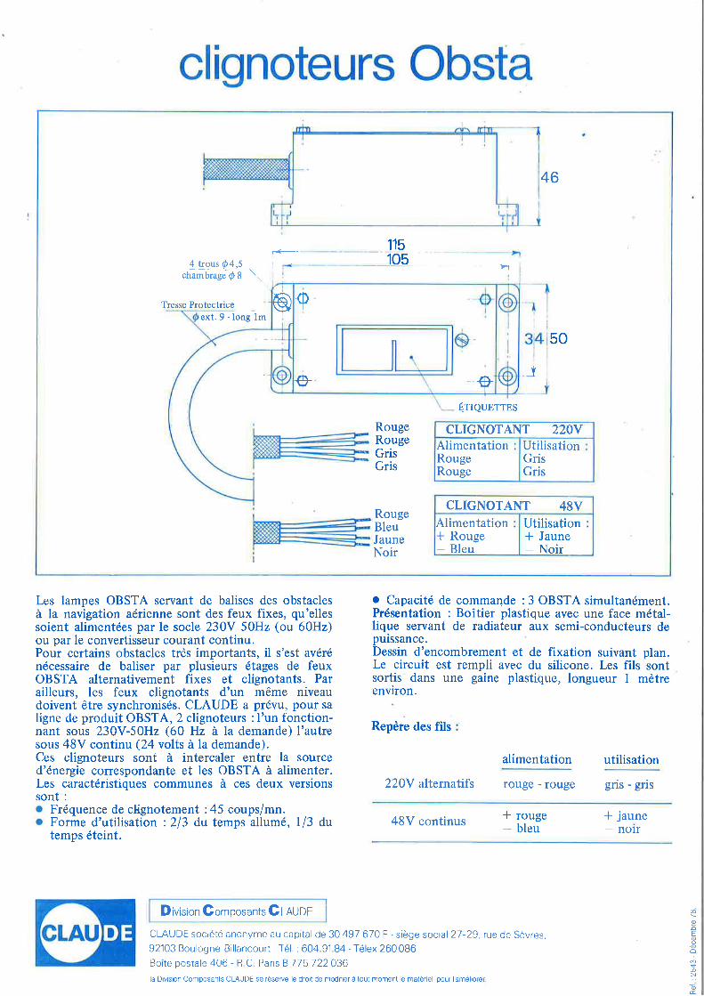
Les lampes OBSTA servant de balises des obstaclesd la navigation adrienne sont des feux fixes, qu'ellessoient alimentdes par le socle 230V 50Hz (ou 60Hz)ou par le convertisseur courant continu.Pour certains obstacles trds importants, il s'est avdrdndcessaire de baliser par plusieurs dtages de feuxOBSTA alternativement fixes et clignotants. Parailleurs, les feux clignotants d'un mdme niveaudoivent 6tre synchronisds. CLAUDE a prdvu, pour saligne de produit OBSTA, 2 clignoteurs :l'un fonction-nant sous 230Y-50H2 (60 Hz i la demande) I'autresous 48V continu (24 volts i la demande).Ces clignoteurs sont d intercaler entre la sourced'dnergie correspondante et les OBSTA i alimenter.Les caractdristiques communes ir ces deux versionssont :
. Frdquence de clighotement :45 coups/mn.
. Forme d'utilisation :213 du temps al1um6, l/3 dutemps dteint.
r Capacit€ de commande :3 OBSTA simultandment.Prdsentation : Boitier plastique avec une face mdtal-lique servant de radiateur aux semi-conducteurs depuissance.Dessin d'encombrement et de fixation suivant plan.Le circuit est rempli avec du silicone. Les fils sontsortis dans une gaine plastique, longueur I mdtreenvrron.
Repdre des fils
alimentation utilisation
220V alternatifs rouge - rouge gris - gris
48V continus * rouge
- bleu* jaune
D ivision Gomposants Gmuor
CLAUDE soci6t6 anonyme au capital de 30 497 670 F - siege social 27 -29, rue de Sdvres.
92103 Boulogne-Billancourt - Tel. : 604.91.84 - T6lex 260 086Boite postale 40tj - R.C. Paris B 775 122036la Division Composants CLAUDE se reserve le droit de modifier a tout moment le mat6riel pour l'ameliorer.
@NIoEo.oo
@I.oE
tCLAU
- nolr
Obsta extension cord
LAMPEOBSTA
H.V. Cdble@ext. 10
1
L.-
I
I
+t-
I\-lt-
\oo\ s
i
lI i
I
tt
I
Irt_.
lt_
6\o OBSTA
BallastI
I
L.
rI
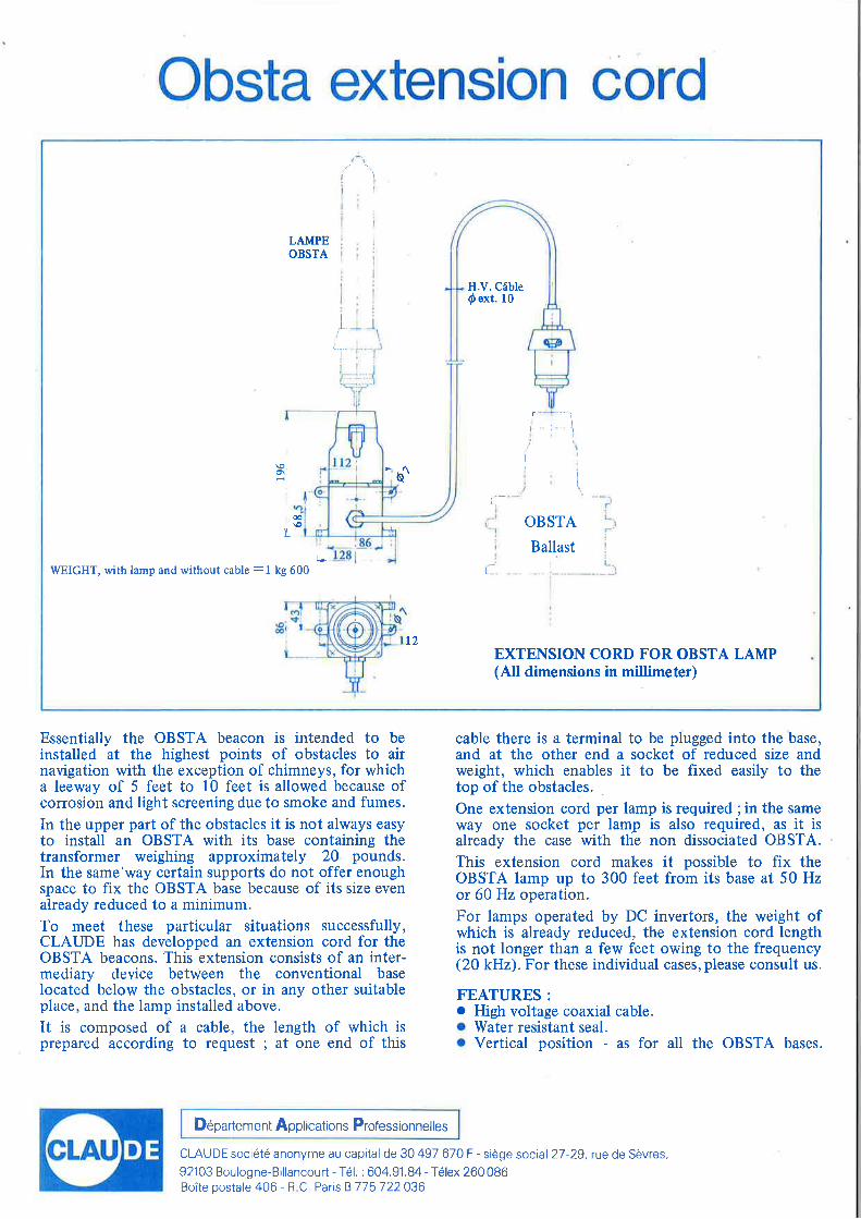
WEIGHT, with lamp and without cable :1 kg 600
l2EXTENSION CORD FOR OBSTA LAMP(All dimensions in millimeter)
Essentially the OBSTA beacon is intended to beinstalled at the highest points of obstacles to airnavigation with the exception of chimneys, for whicha leeway of 5 feet to l0 feet is allowed because ofcorrosion and light screening due to smoke and fumes.
In the upper part of the obstacles it is not always easyto install an OBSTA with its base containing thetransformer weighing approximately 20 pounds.In the same'way certain supports do not offer enoughspace to fix the OBSTA base because of its size evenalready reduced to a minimum.To meet these particular situations successfully,CLAIJDE has developped an extension cord for theOBSTA beacons. This extension consists of an inter-mediary device between the conventional baselocated below the obstacles, or in any other suitableplace, and the lamp installed above.
It is composed of a cable, the length of which isprepared according to request ; at one end of this
cable there is a terminal to be plugged into the base,and at the other end a socket of reduced size andweight, which enables it to be fixed easily to thetop of the obstacles.
.
One extension cord per lamp is required ;in the sarneway one socket per lamp is also required, as it isalready the case with the non dissociated OBSTA.This extension cord makes it possible to fix theOBSTA lamp up to 300 feet from its base at 50 Hzor 60 Hz operation.For lamps operated by DC invertors, the weight ofwhich is already reduced, the extension cord lengthis not longer than a few feet owing to the frequency(20 kHz). For these individual cases, please consult us.
FEATURES :
o High voltage coaxial cable.o Water resistant seal.. Vertical position - as for all the OBSTA bases.
D6partement Applications Professionnelles
CLAUDEsoci6t6 anonyme au capital de 30497 670F - sidge social 27-29,rue de Sdvres,
92103 Boulogne-Billancourt - T6l. : 604.91.84 - T6lex 260 086Boite postale 406 - R.C. Paris B 775 722036
prolongateur Obsta
LAMPEoBs TA
Cdble coaxial@ext. 10
ilIi'i i
rt-)
I€l
O\i tI
l
I
:
I
socle OBSTA
Ballast
I
It_.
)
I
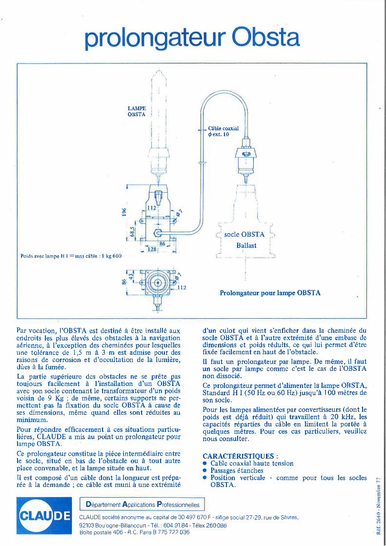
Il*Poids avec lampe H I =sans cdble : I kg 600
\oi00!.t l2
Prolongateur pour lampe OBSTA
Par vocation, I'OBSTA est destind d 6tre installd auxendroits les plus 6lev6s des obstacles i la navigationadrienne, i I'exception des chemindes pour lesquellesune toldrance de 1,5 m i 3 m est admise pour desraisons de corrosion et d'occultation de la lumidre,d0es i la fumde.
La partie sup6rieure des obstacles ne se prdte pastoujours facilement a l'installation d'un OBSTAavec $on socle contenant le transformateur d'un poidsvoisin de 9 Kg ; de m6me, certains supports ne per-mettent pas la fixation du socle OBSTA ir cause deses dimensions, m6me quand elles sont rdduites auminimum.Pour rdpondre efficacement i ces situations particu-lidres, CLAUDE a mis au point un prolongateur pourlampe OBSTA.
Ce prolongateur constitue la pidce intermddiaire entrele socle, situ6 en bas de I'obstacle ou ir tout autreplace convenable, et la lampe situde en haut.Il est composd d'un cdble dont la longueur est prdpa-r6e i la demande ; ce cdble est muni i une extrdmitd
d'un culot qui vient s'enficher dans la cheminde dusocle OBSTA et d I'autre extrdmitd d'une embase dedimensions et poids rdduits, ce qui lui permet d'6trefix6e facilement en haut de l'obstacle.Il faut un prolongateur par lampe. De m€me, il fautun socle par lampe comme c'est le cas de I'OBSTAnon dissoci6.
Ce prolongateur permet d'alimenter la lampe OBSTA,Standard H I (50 Hz ou 60 Hz) jusqu'i 100 mdtres deson socle.
Pour les lampes alimentdes par convertisseurs (dont lepoids est ddji rdduit) qui travaillent d 20 kHz, lescapacitds rdparties du cdble en limitent la port6e iquelques mdtres. Pour ces cas particuliers, veuilleznous consulter.
CARACTERISTIQUES :
o Cable coaxial haute tensiono Passages dtanches. Position verticale - comme pour tous les socles
OBSTA.
D6partement Applications Professionnelles
CLAUDE soci6t6 anonyme au capital de 30 497 670 F - sidge social 27-29, rue de Sdvres,
92103 Boulogne-Billancourt - T6l. : 604.91.84 -T6lex 260086Boite postale 406 - R C. Paris B 775 722036
rro.o
ooz+\oNqi\o&
Autonomous ffied Vffiffi"ffimmg Light
l.C
lf#"r-t;=!,k,:*$
ftl:!
I
*r'1
i
.4i
'"?
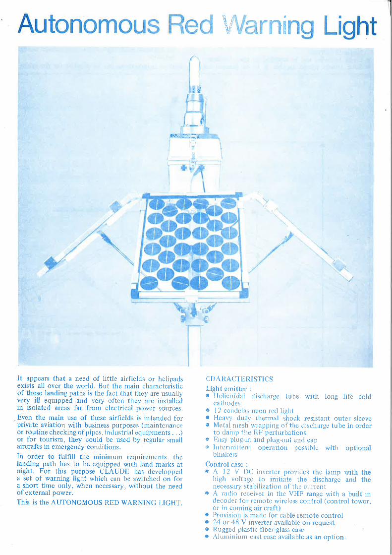
It appears that a need of little airfields or helipadsexists all over the world. But the main characteristicof these landing paths is the fact that they are usuallyvery ill equipped and very often they are installedin isolated areas far from electrical power sources.
Even the main use of these airfields is intended forprivate aviation with business pul'poses (maintenanceor routine checking of pipes, industrial equipmer-rts. ..)or for tourism, they could be used by regular srnallaircrafts in emergency conditions.In order to fulfill the minimum requirements, thelanding path has to be equipped with land marks atnight. For this purpose CLAUDE has developpeda set of warning light which can be switched on fora short time only, when necessary, without tlie needof external power.
This is the AUTONOMOUS RED WARNING LIGHT.
CHARACI'ERISTICSLight ernitter :
o Helicoidal discharge tube with long life coldcathodes
o 1 2 candelas neon red lighto Heavy duty thermal shock resistant outer sleeveo Metal mesh wrapping of the discharge tube in order
to dainp the [tF perturbationso Easy plug-in and ph-rg-out end cap$ lntermittent operation possible with optional
blinicers
Control case :
s A 12 V DC inverter provides the lamp with thehigh voltage to initiate the discharge and thenecessary stabilization of the current
o A raclio receiver in the VHF range with a built indecocler for remote wireless control (control tower,or in coming air craft)
e Provisiotr is made for cable remote controlc 24 or 48 V inverter available on requeste Rugged plastic fiber-glass casec Aluminium cast case available as an option.
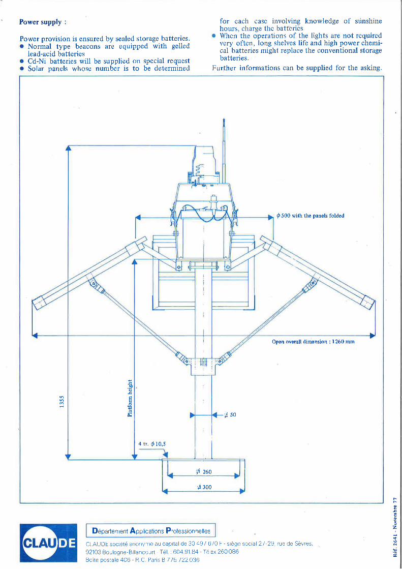
Power supply for each case involving knowledge of srinshinehours, charge the batt'eries
r When the operations of the lights are not requiredvery often, long shelves life and high power chemi-cal batteries might replace the conventional storagebatteries.
Further informations can be supplied for the asking.
Power provision is ensured by sealed storage batteries.. Normal type beacons are equipped with gelled
lead-acid batteries. Cd-Ni batteries will be supplied on special requesto Solar panels whose number is to be determined
I
4 tr. d 10,5
ut)o
trod
il zao
fl 300
0 500 with the panels folded
Open overall dimension : 1260 mm
ds0
D6partement Applications Professionnelles
CLAUDE soci6t6 anonyme au caprtal de 30 497 670 F - sidge soctal 27 29, rue de Sdvres
92'103 Boulogne-Billancourt - Tel. : 604 91.84 - T6lex 260 086Boite postale 406 - R C Paris B 775 722036
rroooo2
+\ocrh\o
il
:i
l-
\
I
l
l" -*
3
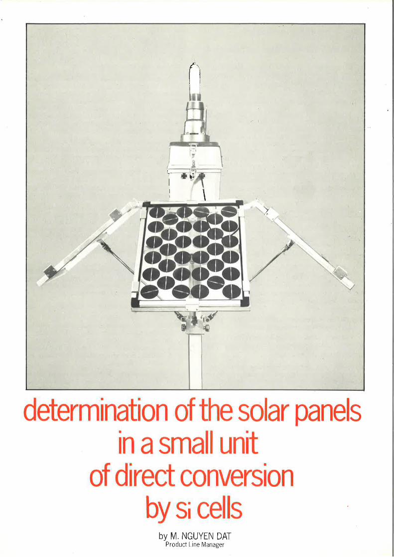
determingtion of the solar panels
in asmall unitof direct conversion
by si cellsby M. NGUYEN DAT
Product Line Manager
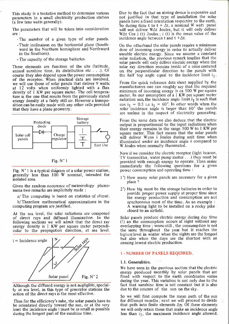
This study is a tentative method to determine variousparameters in a small electricity production station(a few tens watts generally).
The parameters that will be taken into considerationare :
-The number of a given type'of solar panels.
- Their inclinaison on the horizontal plane (South-ward in the Northern hemisphere and Northwardin the Southern).
- The capacity of the storage batteries.
These elements are function of the site (latitude,annual sunshine time, its distribution etc .). Ofcourse they also depend upon the power consumptionof the receptor. When practical data are involved,we will use those of solar panels that deliver 9 wattsat 12 volts when uniformly lighted with a fluxdensity of I KW per square meter. The cell tempera-ture is the one that results from the previously statedenergy density at a fairly still air. However a transpo-sition can be easily made with any other cells providedthat they have a plane geometry.
Protectingdiode
Storagebattery
End Use
Fig. N" I
Fig. N " I is a typical didgram of a solar power station,generally less than 100 W nominal, intended forisolated area.
Given the random occurence of'meteorology pheno-mena two remarks are implicitely made :
a/ The computing is based on statistics of climat.
b/ Therefore mathematical approximations in thecomputing program are justified.
At the sea level, the solar radiations are composedof direct rays and diffused illumination. In thefollowing sections we will admit that the direct rayenergy density is 1 KW per square meter perpendi-cular to the propagation direction, at sea level.
i: Incidence angle N
Solar panel Fig. N'2
Due to the fact that an aiming device is expensive andnot justified in that type of installation the solarpanels have a fixed orientation respective to the earth.So during time t to t * At, a nominal W watt panelwill not deliver WAt Joules, but it will only deliverWAt Cos i (t) Joules ; i (t) is the mean value of theincidence angle between t and t +At.
On the otherhand the solar panels require a minimumdose of incoming energy in order to actually deliveruseable electric energy. Since we assume a constantsolar radiation, the previous remark implies that thesolar panels will only deliver electric energy when thesolar ray direction remains inside of a cone centeredon the perpendicular direction to the panels withthe half top angle equal to the incidence limit i1.
From the quick reference data sheet supplied by themanufacturers one can roughly say that the requiredminimum of incoming energy is ca 500 W per squaremeter. In our assumption of a I KW per square meterradiation sun,the incidence angle limit i1 is such thatcos i,r : 0.5 i,e ir : 60'. In other words when thesolar'incidenc. un'gle is larger than 60" the panelsare useless in the respect of electricity generating.
From the same data we also deduce that the electricoutput is proportionnal to the input radiations whentheir energy remains in the range 500 W to I KW persquare meter. This fact means that the solar panelswill deliver W cos i Joules during unit time whenilluminated under an incidence angle i compared toW Joules when normally illuminated.
Now if we consider the electric receptor (light beacon,TV transmitter, water pump motor . . .) they must beprovided with enough energy to operate. Then araiseimmediately the following questions for a givenpower consumption and operating time :
I ") How many solar panels are necessary for a givenplace ?
2 ") How big must be the storage batteries in order toprovide proper power supply at proper time sincethe energy production and consumption are notsynchronous most of the time. As an example :
A warning light to be installed on a rocky pikeclosed to an airfield.
Solar panels produce electric energy during day time(!) an the consumption occurs at night without anyoverlapping time ; worse still , the consumption is notthe same throughout the year but it reaches thehighest level in winter when the nights are the longestbut also when the days are the shortest with anensuing lowest electric production.
Although the diffused energy is not negligible, special-ly at sea level, in this type of generator stations theaction of the direct rays is the most effective.
Thus for the efficiency's sake, the solar panels have tobe orientated directly toward the sun, or at the veryleast the incidence angle i must be as small as possibleduring the longest part of the sunshine time.
1 . NUMBER OF PANELS REQUIRED
1.1. Generalities.
We have seen in the previous section that the electricenergy produced monthly by solar panels that arefixed with respect to the earth coordinates variesduring the year. This variation is not only due to thefact that sunshine time is not constant but it is alsodue to the courses of the sun on the sky.
So we will first compute the mean path of the sunfor different months; next we will proceed to dividethat path into finite elements An. Ot these elementswe will only retain those that make an incidence angleless than i1, the maximum incidence angle allowed.
-lr- I
TT
Solar cellpanels
Chargeregulator
Thus, for a 24 hour revolution of the sun we willdefine the following quantities (fig. 3)
Sr : ) A4: equal to 24 hours' whole path
Sr:)A?:daytime" Sun abovethe horizon
S2 : ) A4 : useable daY time"cosi)cosi1
54 :.) A4 Cos i : Incidence weighted useable day
cos i ) cos i1 time
The proportion of useable day time for a given monthis then!.r and the equivalent normal incidence time iss4 s;s2
Concerning the actual sunshine time for month n weonly know' the global statistical data supplied bymeteorological organisations such are the worldmeteorological Organisation based in Geneva. Butexcept for particular microclimats we can assumethat the sunshine time for a month is throughoutlyand evenly distributed over the day. (No periode ofthe day is more favored by sunshining than othersregarding its occurence).
Thus from the WMO data one can compute theuseful portion of the sunshine time at a given placefor each month of the year by the relation :
(l) h'n: hnx?A cos i(cosi)cosi1) . : hn x!4
) A4 (sun above the horizon ) " 52
1,2. Mathematical expressions
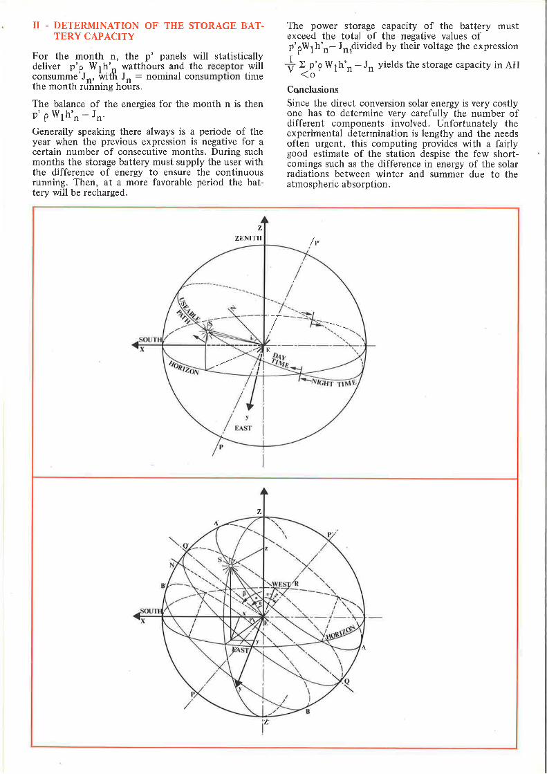
On the fig. 4 is represented the celestial sphere.The earth is located in the center E.
P'P : Direction of the poles.QQ' : Projection of the equatorial circle of the
earth onto the celestial sphere
E,;,f,t' : Direct reference axes.
fr : Zenith of the place.
E; : South direction.
El : East direction.++Ez and EQ' define an angle in the xEz plane. Thisangle is equal to the lg.!i!udq- of the place. We willadont the rule that (82. EO') is counted oositivewtren trO' is on the side oi ilrespective^to Ha ) o for the Northern Hemispherecl ( o for the Southern Hemisphere.
The sun path for each day is an element of a spiralwound on the celestial sphere. In the approximationsof our problem we will consider it to be a circle.Furthermore we only consider a mean circle for eachmonth. One of such a circle is materialized by AA'.The plane that contains AA'is perpendicular to P'P.ER is the distance of the center of AA' to the origineE of the reference axis.
Taking the radius of the celestial sphere to be unit,we easily,find that :
At the equinoxes ER : 0;Sunpath : Circle QQ'At the soltices ER : + sin 23" 27' ; Circle AA' or BB'.
Eo:r the other months of 'the year we will admit thatER varies as a sine function of time. So the generalexpression of ER is represented by.
(2) ER : sin n' zr sin 23" 27' with6
n being the rank of the month,+
From the obvious symetrical pattern ER is locatedin the xEz plane and its coordinates are :
n': n - 3 if n23n':n+9 ifn(3
+ sin 23' 27' sin n0sin 23' 27' sin n
7r'cos-{zr sin6
(n-a)
(r-a)(3) en
x,y,z, being the coordinates of the sun S.the twoequuiions ihat represent the path of the 3un are :
_++(4) ER.RS : 0 (The sun is on ttr: plane perpendiElar
to FF at ttre distance ER)'
(5) x2 I y' I z2 : | (The sun is on the Celestial sphere)++ -+ -+ --> +_+
(6) Since ER.RS : ER (ES - ER) : ER.ES - ERz
(4) and (5) became :
(7) x sin 23' 27' sin n' ?r cos Qr - at) *z sin 23" 27'6
sin n' zr sin (tr - a ) - sin2 23' 27' sin2 n'zr - 066
(8) x2 *y'*22 : I
Obvously the symetry of the figure suggests that thesolar paqgl eris N is to be on the xEz plane. p is the346rIe'(ET, N) with the same sign rule as for o. SoEN is represented by :
sin p0cos p.
The condition that the solar rays fall on the panel inthe useful range is expressed by :
--++(9) cos (ES,EN) ) cos i1
or(10) x sin B *z cos p ) cos i1
1.3. Practical micro-computer procedure.
As we can see one possible program that has beenwritten on Serie 2200 Wang micro computer, themain steps to follow are :
First, one has to enter,o , latitude of the place consi-dered, and B the angle between the solar panels andthe horizontal plane.
The panels will be facing Southward in the NorthernHemisphere and conversely Northward in the Sou-thern Hemisphere.
Next the computer is to be fed with the maximumincidence angle tolerated, either by its value i1 or byits cosine function cos i1. This parameter -is theexpression of the lowest'energy density that willactivate the solar panels. In the case of usual cellsit will be cos il : 0.5.
In order to calculate the ratio between the actuallyuseful time and the total sunshine time, the followingitems will be computed in the stated order :
- Determination of fr vali;e corresponding tothe month n.
ER : sin 23' 27' sin n'
-+EN
n*9 if n(3n-3 if n23
n7r
T
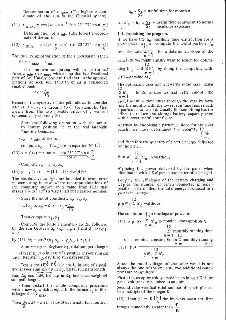
- Determination of z max. (The highest z coor-dinate of the sun in the Celestial sphere).
(l l) z max.: cos [a - sin -t (rin 23" 27' sin n'g)]6
- Determination.of z min (The lowest z coordi-nate of the sun).
(12) z min.: cos [ (r - T - cos-l (sin 23'27'sin n' zr)]26
The total range ofvariation of the z coordinate is then
Az:zmax-zmin
- The iterative computing will be performedfrom z min to z max with a step that is a fractionalpart of Az. Usually one can find that, in the approxi-mations we seek for, 1/50 th of Az is consideredsmall enough.
8z: Az50
Remark : the symetry of the path allows to considerhalf of it only, i.e. from Q to Q' for example. Thatmeans from the two possible values of y we willsystematically choose y > o.
- Start the following operation with the sun atits lowest position, ie at the real midnighttime as a begining.
- zo: z min of the sun
- compute xo : 1(zo); from equation N' (7)
(13) x : f (z) : z tan a - sin 23' 27' sin n' T6cos a
followed1 (x1.v1.
hr, *!^S : useful time for month ns2
an h'r, : hn * !+ : yt.fgl time equivalent to normal, " -' S; incidence exposure.
1.4. Exploiting the program.
If we have the h-. sunshine time distribution for agiven place, *"^c'dn compute the useful portion h'r,
l2and the total ) h'n for a determined slope of the
n: Ipanel (0).We might equally want to search for optimi-
I2zing h'n and ) hfl_ by doing the computing with-- n:ldifferent value of B.
The optimizing does not necessarity mean maximizingt2> hh In Some case we had better smooth then:l
useful sunshine time curve through the year by favo-ring the months with the lowest sun time figures witha particular value of B. Usually this smoothing has foreffect to reduce the storage battery capacity evenwith a lower useful hour figure.
Anyway by choossing a particular slope for the solarpanels, we have determined the quantity 12
rhhn: I
and therefore the quantity ofelectric energy deliveredby the panel:
l2w:wl >n: I
W 1 being the power delivered by the panel whenilluminated with I KW per square meter of solar light.
Let p be the efficiency of the battery charging andlet p' be the number of panels connected in serie -parallel. pattern, then the total energy produced in ayear ls rn average :
t2p pWt ) h'r, watthour
n: I
The condition of 4o shortage of power is12
(16) p p W1 X h'n 2 nominal consumption {n:l nn: I 12
or nominal consumption x X monthly runningn: I time
(17) e).- l2pW1 ) !'nn: I
Since the rated voltage of the solar panel is notalways the one of the end use, two additional condi-tions are compulsory :
First : the receptor voltage must be an integer K if thepanel voltage is to be taken as an unit.Second : the eventual total number of panels p' mustbe a multiple of the integer K.
(18) Then p' : K tftl tfre brackets mean the first
integer immediatly greater ttran IllK
- Compute yo : g (xo,zo)
(14) V : g(x,z): * [I I - (x2 +22)Iltlz
The absolute value signs are intended to avoid errorin computing in case where the approximations ofthe computer induce an x value from ( 13) thatmakes I - (x' *22) avery small but negative number.
- Store the set of coordinate xo, yo,zo.
-Letz1 be zo *6 z: zo+&5U
- Then compute xl,y1- Compute the finite elementary arc Lr1
by.the sun between So (xo, yo, zo) and S,1.)
bV (15) An: cos-l (xl.xo * yl.yo -f zyzo)
- Sum Aq up in Register S 1 , total sun path length
-Test if z1) o in case of a positive answer sum A4up in Register 52, day time sun path length.
--++-Test if cos (EN, ES1) ) cos i1 in case of aposi-
tive answer sum A4 up in 53, useful sun path length ;
Sum A4 co, (fr 6 "O
in 54, incidence weightedsun path length.
- Then restart the whole computing procedureyJh a new zo which is equal to the former zl until z,ls larger than z -u*.Then $ x24: mean value of day length for month n.
si
II - DETERMINATION OF THE STORAGE BAT-TERY CAPACITY
For the month n, the p' panels will statisticallydeliver p'p Wrh'. watthours and the receptor willconsumm-e'Jn, ivitt Jr, : nominal consumption timethe month running hours.
The balance of the energies for the month n is thenP'pW1h'n-Jn'Generally speaking there always is a periode of theyear when the previous expression is negative for acertain number of consecutive months. During suchmonths the storage battery must supply the user withthe difference of energy to ensure the continuousrunning. Then, at a more favorable period the bat-tery will be recharged.
The power storage capacity of the battery mustexceed the total of the negative values ofp'pW1h'n- Jrr.divided by their voltage the expressionI )p'V p Wlh'r, - J' yields the storage capacity in AH(oCqnclusions
Since the direct conversion solar energy is very costlyone has to determine very carefully the number ofdifferent components involved. Unfortunately theexperimental determination is lengthy and the needsoften urgent, this computing provides with a fairlygood estimate of the station despise the few short-comings such as the difference in energy of the solarradiations between winter and summer due to theatmospheric absorption.
E
zZENITH /v'
Z
A
A
z'
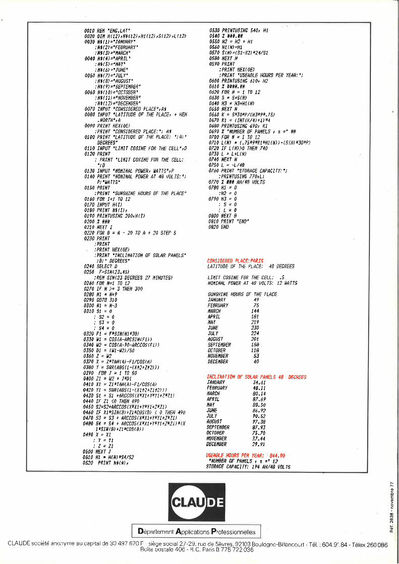
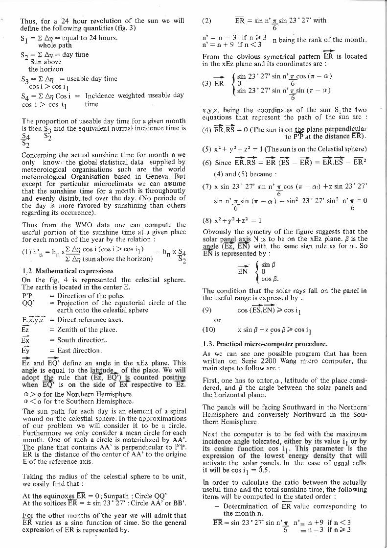
OATO frEII 'ENE.LAT'002A DIil H(121 'JllItil tHt(lil rS(lil tLtl2)0030 lll(l)='trANUARY'
: Nl(il ="FEERUARY': Nl( il ="llAREH'
004A N(il='APRIL': lll(51='llAY': lll{il ='IUNE'
0450 ill(7)='IULY": Nl(il='AUEUS|': Nl(il "'SEPfEllEERu
0080 lll(til="flCfflEER': lll( tl) ='tl0UEllEER': lll( lil.'DEEEIIBEft'
4070 INPAI ." tfltlSIDFrtFO Ftrit'F'rd$0A80 INFUT 'LAIIIUDE 0F fHE PLAtEt + HElt
.llflftTf'tA00la PRIilI HH(|hE)
:FRINI ,EAilSIDEEED PLACE:,i A$AIOO PEIIII 'LAIITUDE OF THE PLAEE; ';A;O
0F0,tFFS'0110 INPUI 'lIlUI C05I/{E FlR IHE CELL"IAO12O FRINI
i PfLYf 'UilIT ClSINE Faft fHE EELL:
'; I)4130 IilPUf "il0ltINAL F0llERt ilAllS"rP0140 PRINI "Np,|fINAL F?UEE Ar 48 VELfS:"i
P;'llAfTS"0150 PRIilt
:PRIII| 'SUIISHIIIE HOUfrS OF THE PLAEE"UEA FOn I=1 l0 120t70 IilPUT H(I)0180 PRINI tll(I)r0190 PRIiltUSIilE ?Ab H ( I)0240 z il##O2IO NEXI I02?0 F0n B = A - ?0 l0 A + 30 SfFP 5OfiA FRIilT
,'FfLVf..FfIilT HEX(OE)jPfLYf 'ItClIiltlIAN 0F S0LAR FAdElS'i8r' ,F6fEES'
0210 sELEtr D
0250 F=tlll(23.45)ifFlt $J,Y(33 OgGfFF.9 27 llIllUTES)
A26A F0,R N.I fA E0270 IF rY '\. J IHFrY J000280 lll . tl+90290 EAru iloN0A Nl = N-34310 Sl = 0
;$3=0.'sJ--0;$4=0
0320 Fl = F*5IN(N1*30)0330 Ul = CASTA-AfttSIN(Fl))4340 ll2 = t09tA-?0-ARCffiS(Fl))A350 Dl = I(l-ll?)/S00360 Z = ll203/0 X = ZrfAil(il-FMt1i(il0380 Y = 50ft(ABS(1-(Xll+ZlU))0310 F0RI.1f0S00400 Zt = Up + IttDl04lA Xl . Il*lAN(A,-FL/tEt(A)0420 YI = SEft(ABS(t-(X112+1,1til))0130 st s 5l +dRcc0${.yfxj+ysrj+JfuJj0140 IF Zt $ IHEN 4v00450 slssl+Ancc05 { xr x | }Y *Y I +zrz I )0460 IF /'1*St1(ilr21*C0S(B] { 0 THEN 4?00470 5I = 53 + AfCC0SrXr{l+yryl+ZrIl]0180 54 = ,94 + AfDC05{X*JI}f*}'I+Z.qJ){(X
I rS.t,V{8, +/I *CrS(8.} )0494 X = Xt
:Y.fl!Z=Z!
0s00-ilExT IASt| Ht = H(1ilx54/520520 PRII{'T llt(ll) r
ASJO PRIIIIUSINE 540' HT
4510 z, il#.##0550 HZ = HP r HI0560 H|(iil=Hl0570 S(M=(51-5il*24/510580 ilEXt N
OSIO FRIliT:PRINI HEX(0.E):PRIIIT "USEAELE HOUfrg PER YEAR:'i
A4AA PEINIUSTNE 6Tb H206IA Z ##il#.##0420 F0R lt = I f0 12n6g 5 x 8+5(tl)0t10 Hi . HI+Hl(ll)06s0 ilExf N06t0 K = s$a*P/(H3r9*.75)0670 RI : ( Iill(lv4)+1)*40i80 PRIil|USINE 49At KtA6?0 Z 'tlUllBER 0F PAIIELS r n =' ##0700F0RN=tf0|t0/10 L(M e (,l$tttlfi*fll ftil ) - (5 (M r30.rP)0710 IF 1ftil)l tuEtt 7400730 L = L+L(N)0/40 ilExt il0750 L . -L/484760 PRItll '5r0'?46F CAPA|IIY:'j
:PRIlllUSIllE 770tLi0770 ? *## AH/48 UuL|SA780 Hl = 0
:H2 = 00710 HJ = 0
,'S=0! L=0
OEOO NEXT BO81O PRITII 'END'O82O END
TOTSIOFfED PLACE: PARISLAII|UDE OF IHE FLATE: {9 DEfRFES
LII,IIT TOSINE F,.R fHE EELL: .5NollIllAL PaUEE AT 4F Utl I$'i 12 UArTs
{,SEABI.E HoURS PEE YEAR: 841,'0'/{UnBEn AF PAIIELS t n z' 12
Sfr,?A6E CAFACIIY: 194 AH44S UILIS
sUilgI/ITF HfiURS OF IHE PLAEE
IANUARY 49FFSFd[',r 75ilAnEH t44APNIT J8IilAY 219TUNE fiAilLY 2?4AUGUST 201sgFIElrSEfr 158OTIOEER JT8NOUEIIFER 53DECEIISER 40
INCLIIIAIIOII OF S0,LAR PANELS 4A DEcREFSTAilUANY 34.61FEBRUAEY 48.17ttARcH 80.14APRTL 87.69IiAY 88.50IUilE 86.?2ilLY ?0.s2AUEUST t/.38$gFrFil8FF 87.?3acl0EER 75.70il'vEilFER 37,14DECEIIBER 2?.91
tsNooEo
coo@Nil'otD6partement Applications Professionnelles
CLAUDE soci6t6 anonyme au capital de 30 497 670 F -.siege social 27 -2.9, rue de sevres, 92103 Boulogne-Billancourt - T6l. : 604.g1.g4 - T6lex 260 0g6Boite postale 406 - R C. Paris B 775 722036
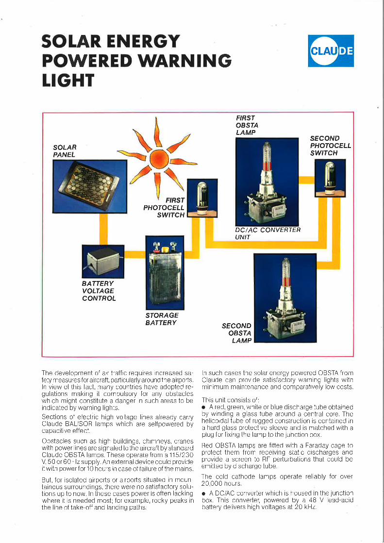
SOIAR. ENER.GYPOWERED WAR.NINGTIGHT
ICLAU
F'RSIOBSIALAMP
SOTARPANEL
SECONDPHOTOCELLswtTcH
PHOTOCELLSWITCH
DC/AC CONYERIERUNIT
BATTERYVOLTAGECONIROT
STORAGEBATTERY SECOND
OBSTALAMP
$gr
The development of air traffic requires increased sa-fety measures for aircraft, padicularly around the airports.ln view of this fact, many countries have adopted re-gulations making it compulsory for any obstacleswhich might constitute a danger in such areas to beindicated by warning lights.
Sections of electric high voltage lines already carryClaude BALISOR lamps which are selfpowered bycapacitive effect.
Obstacles such as high buildings, chimneys, craneswith power lines are signaled to the aircraft by standardClaude OBSTA lamps. These operate from a 1151230V 50 or 60 Hz supply. An externaldevice could provideit with power for 10 hours in case of failure of the mains.
But, for isolated airports or airports situated in moun-tainous surroundings, there were no satisfactory solu-tions up to now. ln these cases power is often lackingwhere it is needed most; for example, rocky peaks inthe line of take-off and landing paths;
ln such cases the solar energy powered OBSTA fromClaude can provide satisfactory warning lights withminimum maintenance and comparatively low costs.
This unit consists of :
o A red, green, white or blue discharge tube obtainedby winding a glass tube around a central core. Thehelicoidal tube of rugged construction is contained ina hard glass protective sleeve and is matched with aplug for fixing the lamp to the junction box.
Red OBSTA lamps are fitted with a Faraday cage toprotect them from receiving static discharges andprovide a screen to RF perturbations that could beemitted by discharge tube.
The cold cathode lamps operate reliably for over20,000 hours.
o A DC/AC converter which is housed in the junctionbox. This converter, powered by a 48 V lead-acidbattery delivers high voltages at 20 kHz.
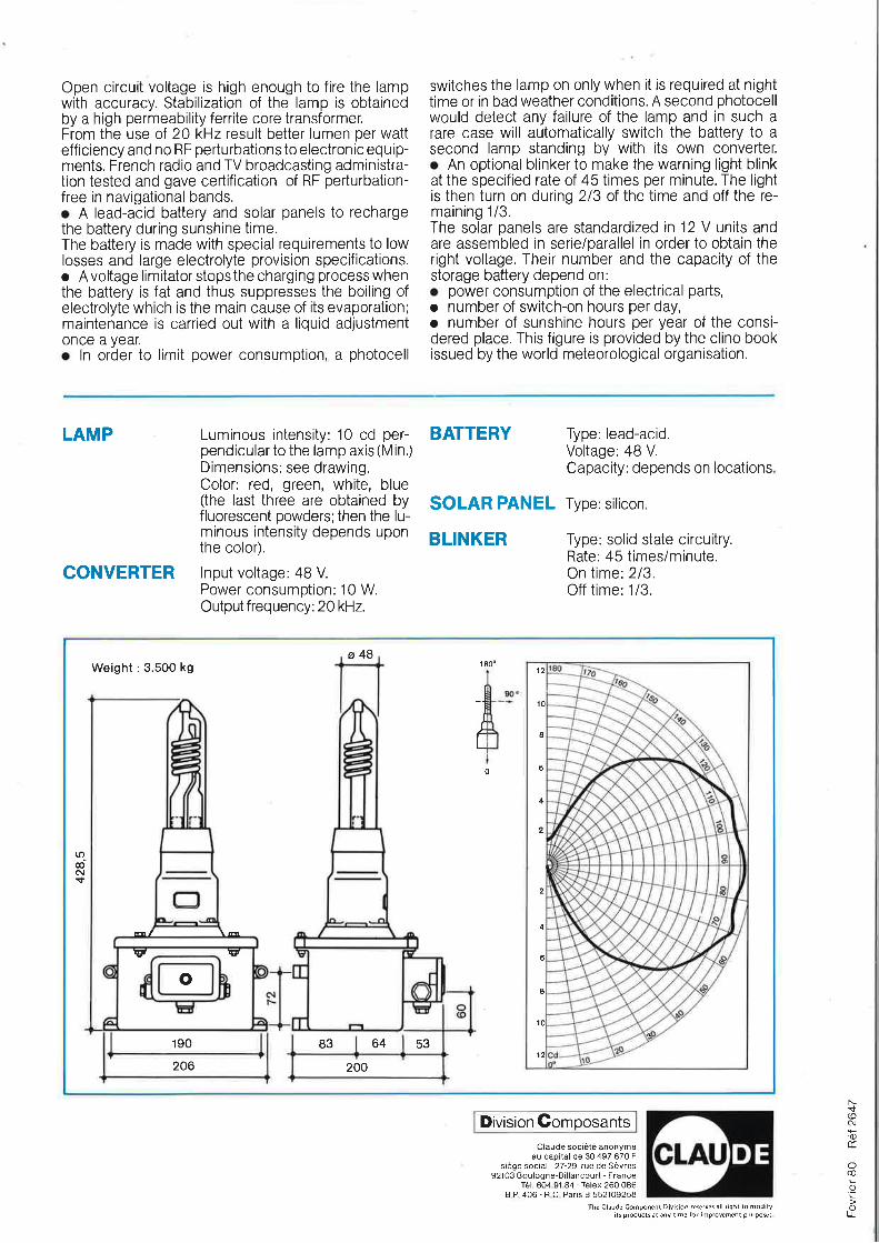
Open circuit voltage is high enough to fire the lampwith accuracy. Stabilization of the lamp is obtainedby a high permeability ferrite core transformer.From the use of 20 kHz result better lumen per watteff iciency and no RF perturbations to electronic equip-ments. French radio and TV broadcasting administra-tion tested and gave certification of RF perturbation-free in navigational bands.o A lead-acid battery and solar panels to rechargethe battery during sunshine time.The battery is made with special requirements to lowlosses and large electrolyte provision specifications.o A voltage limitator stops the charging process whenthe battery is fat and thus suppresses the boiling ofelectrolyte which is the main cause of its evaporation;maintenance is carried out with a liquid adjustmentonce a year.r ln order to limit power consumption, a photocell
switches the lamp on only when it is required at nighttime or in bad weather conditions. A second photocellwould detect any failure of the lamp and in such arare case will automatically switch the battery to asecond lamp standing by with its own converter.o An optional blinker to make the warning light blinkat the specified rate of 45 times per minute. The lightis then turn on during 213 of the time and off the re-maining 1/3.The solar panels are standardized in 12 V units andare assembled in seriei parallel in order to obtain theright voltage. Their number and the capacity of thestorage battery depend on:. power consumption of the electrical parts,o number of switch-on hours per day,r number of sunshine hours per year of the consi-dered place. This figure is provided by the clino bookissued by the world meteorological organisation.
LAMP
CONVERTER
Luminous intensity: 1O cd per-pendicular to the lamp axis (Min.;Dimensions: see drawing.Color: red, green, white, blue(the last three are obtained byfluorescent powders;then the lu-minous intensity depends uponthe color).
lnput voltage: 4B V.
Power consumption: 10 W.Output frequency: 20 kHz.
SOLAR PANEL Type: silicon
BLINKER
Type: lead-acid.Voltage: 48 V.
Capacity: depends on locations
Type: solid state circuitry.Rate: 45 times/minute.On time: 2/3.Off time: 1/3.
BATTERY
a481 800
0
Weight :3.500 kg
190
10
8
6
2
4
2
2
4
0
2
rrOdc\ls
o
\aaf
\P v
200206
83 64 53
Division GomposantsNs(oc\'0)cc
@
0)
.c)LL
Claude soci6te anonymeau capital de 30 497 670'
sidge social : 27-29, rue de Sdvres92103 Boulogne-Billancourt - France
Tel. 604.91.84 - Telex 260 086B.P.406 - R.C. Paris B 552109258
The Claude Component Division reserves all right to modifyitsproductsat any time for improv€ment purposs.
LAI'1PE OBSTA ADF
SYITEME ANTIDEFLAGRANT
mi!e|i1!ri!-$.arnpe d d6charge clans le n6on, cathodes froides,ongue dur6e de vie.
umiere rouge aviation se trouvant clans le domaineetini par
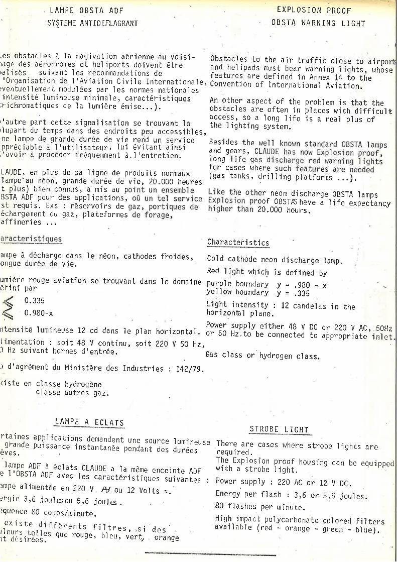
'intensitd lurnineuse minimale, caract6ristjques An other aspect of the problem is that the'richromatiques de la lunridre 6mise...). obstacl., ui* often in places with difficultlautre parr cette sisnatisation se trouvanr ta tf;ltiinni?rl l;l?.;ltt ts a real plus or,lupart du tenrps dans des endroits peu accessibles,
;;,.]:Tff,!"ni?lt?,Hi:,l: YJi [i?t.H? :?;1j.. Besides the weil knou,n standard OBSTA ramps;';5;;i;-;'p'ocoae''iiil;ffi;n;-;.ii.ni..ti.;. iilnni?i:,n::oH?:.l:;n:'1.5-fi]:;l;i ?[f,[;
!:H35'.fi"glx: l:.;1.'Jfli:.05.0;?::'l;.336'il:X.., i;:"ffi;,1'n5i?' iT;i ;i:ll:ffi,'::.neea6rt p'lus) bien connus, a mis au point un ensemble Like the other neon djscharge 0BSTA lampsB$TA ADF pour des applications, o0 un tel service 51nioiion-irmr'ogirA;;;'i tire expectancyst requ'i s . [xs : r6servoi rs de gaz , -port'iques de hi bhe; if.,u[' 20. 000 hours0chargerrent du gaz, plateformes-de-fbrage,affi neries
EXPLOS I ON PROOF
OBS,TA I,IARN ING L ]GHT
,es obstacles d'la nagivation a6r'ienne au voisi- gbstacles to the air traffic close to airporaqe des aerorinornes et heliports doivent 6Lre u;6 h;li;.;; must bear vrarning lights, whos,aljses suivant les recommandations de - featu..r'i.u defined in Annex 14 to the'0rganisatjon de l'Aviation Civjle Internationalu, C;;;;;;;o;'of Intur,national Aviation.rventuel I ement nrodul6es par I es normes nati onal es
e
Characteri sti cs
R0. 335
0.980-x
Cold cathode neon discharge lamp.Red I ight which is def.ined by
PulPle boundary 3l = .980 - xYellor^r boundary 1l = .33S
l-iglt intensity : 12 candelas in thehorizonhl p1ane.
Power supply e,ither 48ntensite lumineuse 12 cd dans le plan horizontal . or 60 Hz.to be connectelimentation : soit 48 V continu, soit 220 V 50 Hz,) Hz suivant bornes d'entr6e.
r d'agr6ment du MinistBre des Industries : t4Z/79.
riste en classe hydrogdneclasse autres gaz.
Gas class or hydrogen class.
V DC or 220 U AC, 50Hzd to appropriate inlet
LA14PE A ECLATSSTROBE L I GHT
rfaings applications demancrent une s0urce lurnineuse
^gl1nd. puissance instantinel-penoant cles durdeseves.
lampe ADF a ecrats cLAuDE a ra mdnre enceinte ADFe l'0BSTA ADF avec rei iiru.toiist'iques suivantes :)nrpe alinrerrtee en 220 V A/ ou 12 Volts =.rrgie 3,6 joul es ou 5,6 joul es .iquence B0 coups/ninute.exi ste dif f 6rents f i I tres, ,si c.les
il'ilp,lEll:' qu. .ors.,'r,r".rl'vert, oranse
There are cases where str:obo f .ights arerequired.The Exp'losion pfogl housing can be equippedwith a strobe tight. --"J
Power supply : ZZ0 AC or 12 V DC.
Energy per flash : 3,6 or 5,6 joules.B0 flashes per minute.Higf- impact polycarbonate colorecl filtersavat tabte (red - orange _ green _ b.lue).
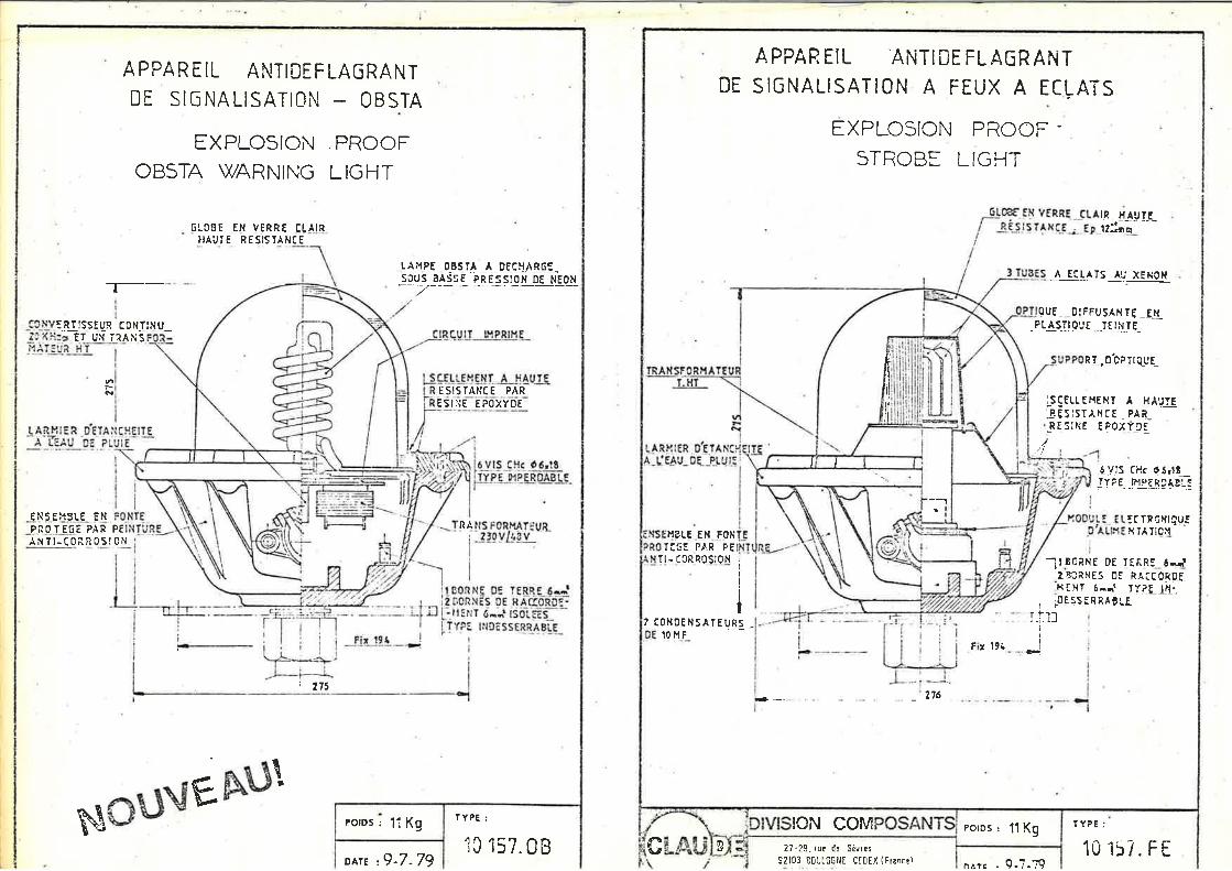
eotog : ll Kg
APPAREIL ANTIDEFLAGRANT
DE SIC NA LISATION OBSTA
EXPLOSIONOBSTA WARNING
PROOF
LIGHT
lRTrsstuR colt-ftltu_ET UN TRA I'i s
F
_qNtEx.3r.E ENPNOTE6E PAR PTANil-C0-n!0il qN
61088 E8 VERRT C-LAlRHAUTE RESISTANCE
F
| 275
r. Ar',tPE 03s.rA _A_D_Eq! g-6_LS|JUS 3A5SE PRESSION DE NEON
E SIS TANT E PARESrse FFoxvbe
-r-.---- -
I
l6vls cHc o6,rELUrl_ryierb_rsre
lrs F0Rr{ArfuL?l! vl_68 v
It4
TYPE:
NE 0E Iq&BE-6!;iNES OE RACIORDq.I 0-j isbl-.es_ -
tNDE ss EBi_48!-E_
\l
NcusEht}lo^tE,9-7-79
ic 157.08 10 i57. F tnroN coM roros ' l't Kg
A PPAR EIL ANTIDE FL AGR ANTDE SIGNALISATION A FEUX A ECLATS
EXPLCSICN PROOF .
STROBE LTGHT
IR HAUTEu::";- ---
-A Ec_t4Tlllv_xlNqN
gut-. _0!FFUSAXTt _!lLPL.AST|QUE
-TE!{,I_E-
g_r*qbpilquE_
LSCELLEHExT A HAUYE
:8!5IST^XCE . PALREsrxE r?oI?_Dq
r,1?rE EN .toxT!6E PAR PE
It - toRFo5!QI
? c0NDENSAT€uR5 _!0 H.F*
1
!I
I
L -.-
Fi, t9{
--lr.2.ti
r.1--rI
I
.6-Y!5 Cl'lc O5rl!Ir?!- !]!F.g!ALf
tc Tn 0xrqu_Er{ tA;iQ,1
tceilE DE T€RRE_ 6n{BCiNES 0E RT.CCoRDJ_EXT 6aJ tYlll!-:E5S€RRA!Lf
TYPE:
_-t4-r.
- --.-. .,
t+"---*"-"--
276
Aq., 27-29,ruz de Sdvres
S2103 B0Ut0Si,li CE0EX {trence}
I I
ili
-'t