De la difficulté d’introduire des polymères et composites...
75
De la difficulté d’introduire des polymères et composites dans l’industrie automobile Gérard Maeder Président de l’Association Française de Mécanique Ancien Directeur de l’Ingéniérie des Matériaux de Renault
Transcript of De la difficulté d’introduire des polymères et composites...
De la difficulté d’introduire des polymères et composites dans
l’industrie automobile
Gérard MaederPrésident de l’Association Française de Mécanique
Ancien Directeur de l’Ingéniérie des Matériaux de Renault
0
2
4
6
8
10
12
14
16
18
2019
61
1968
1969
1972
1975
1976
1978
1982
1984
1985
1988
1990
1992
1993
1994
1995
1998
2000
2001
Wei
ght o
f pol
ymer
mat
eria
ls /
car
(%)
R4 R
6
R5
R12
R30 R14
Sup
er 5
R9
R18
R25
R19
Clio S
afra
ne
Tw
ingo
Lagu
na
Még
ane
Clio
II Lagu
na II
Vel
Sat
is
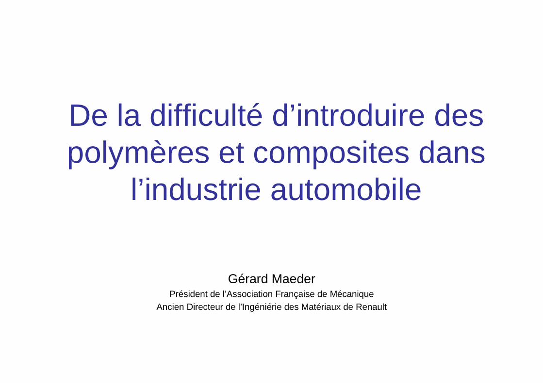
Weight evolution of plastics in Renault cars
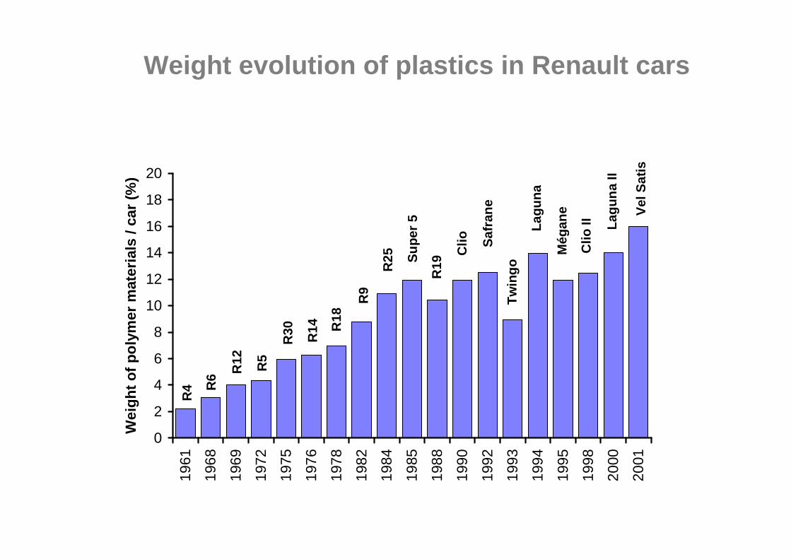
• Un véhicule se décompose en 7 grandes catégories de matériaux. Il est constitué en moyenne de :
• Part métallique / part plastiques
Les matériaux utilisés dans l’automobile
74%
5%3% 3%
12%
1%2%Métaux
Polymères
Elastomères
Verres
Fluides
Matériaux naturels
autres
9%
6%
56%
26%
1%1%
1%
Acier
Aluminium
Fonte
Cuivre
Plomb
autres métaux
autres matèriaux
PE9%
PES6%
ABS5%
PA6%
PUR-E11%
Autres17%
PP46%
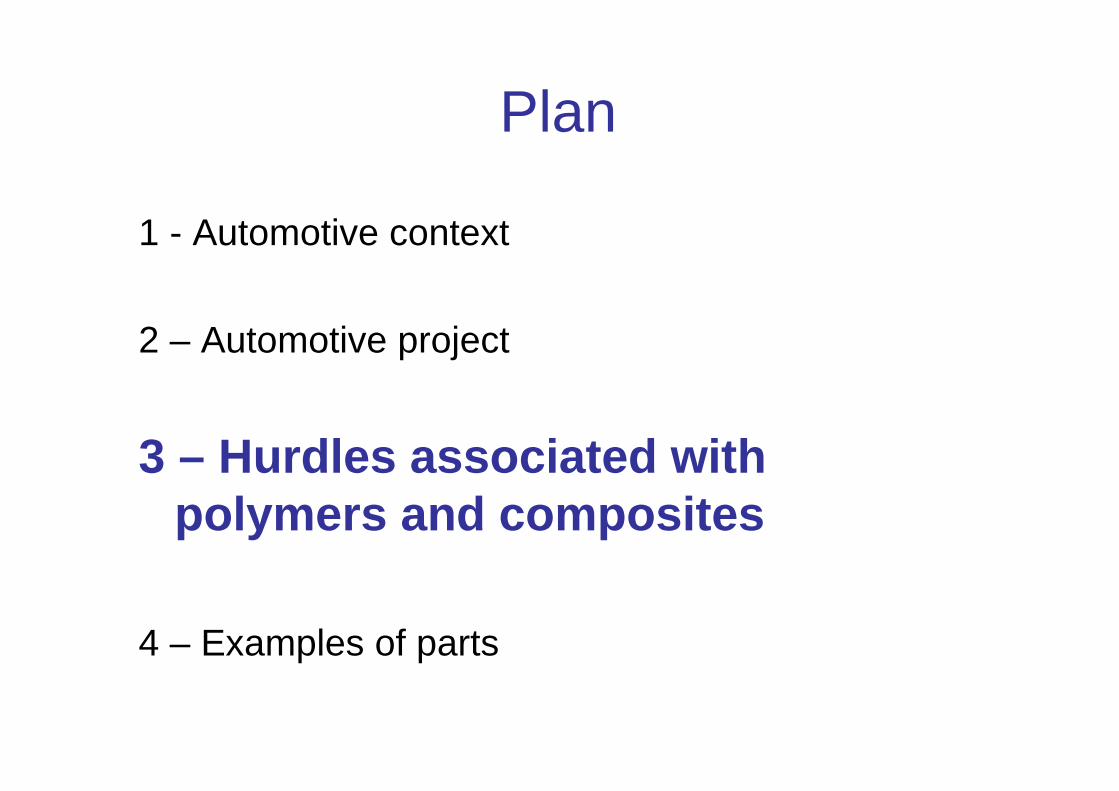
Plan
1 - Automotive context
2 – Automotive project
3 – Hurdles associated with polymers andcomposites
4 – Examples of parts
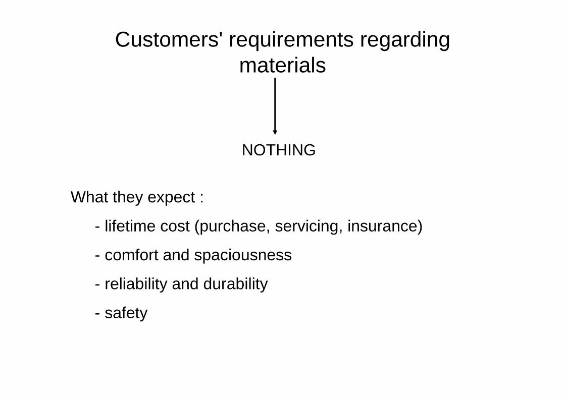
Customers' requirements regarding materials
NOTHING
What they expect :
- lifetime cost (purchase, servicing, insurance)
- comfort and spaciousness
- reliability and durability
- safety
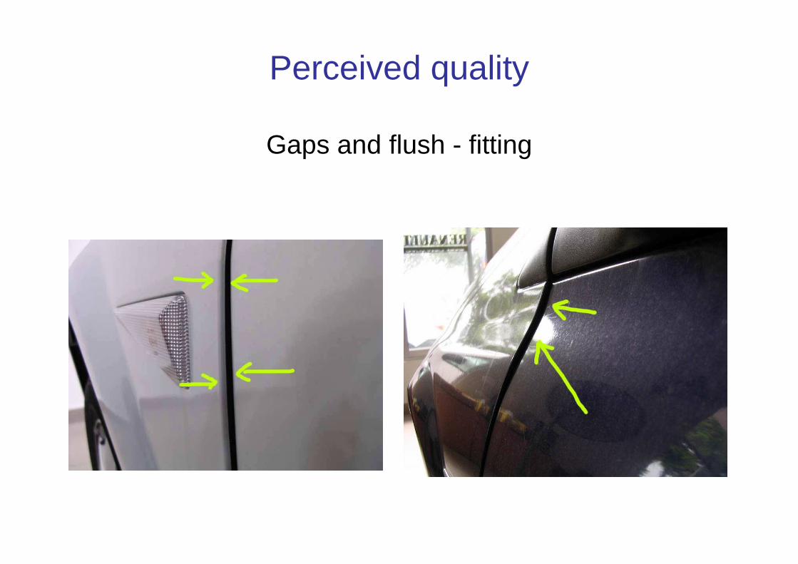
Perceived quality
Gaps and flush - fitting
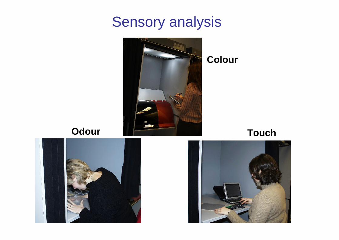
Sensory analysis
Colour
TouchOdour
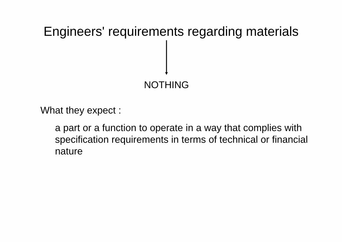
Engineers' requirements regarding materials
NOTHING
What they expect :
a part or a function to operate in a way that complies with specification requirements in terms of technical or financial nature
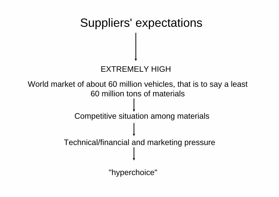
Suppliers' expectations
EXTREMELY HIGH
World market of about 60 million vehicles, that is to say a least 60 million tons of materials
Competitive situation among materials
Technical/financial and marketing pressure
"hyperchoice"
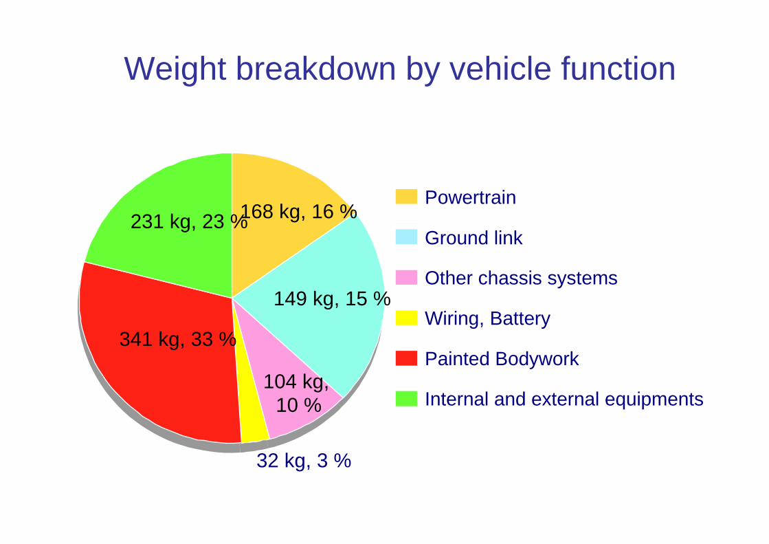
Weight breakdown by vehicle function
32 kg, 3 %
Powertrain
Ground link
Other chassis systems
Wiring, Battery
Painted Bodywork
Internal and external equipments
168 kg, 16 %
149 kg, 15 %
104 kg,10 %
341 kg, 33 %
231 kg, 23 %
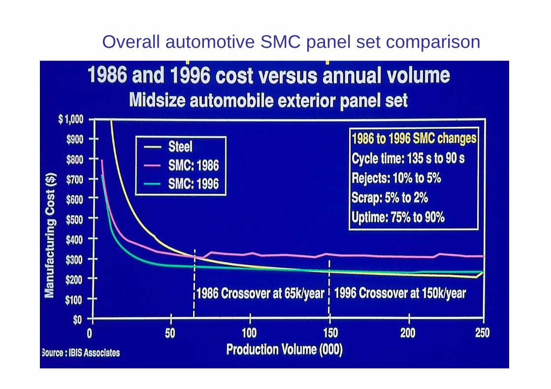
Overall automotive SMC panel set comparison
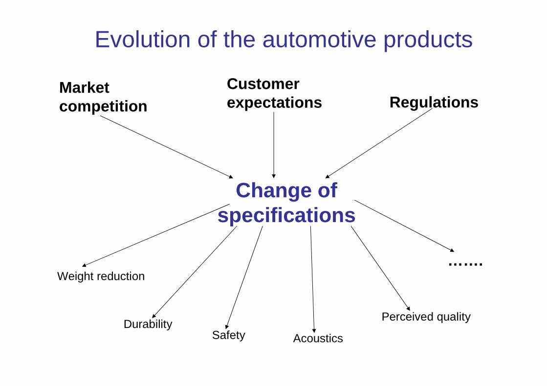
Evolution of the automotive products
Change of specifications
Market competition
Customer expectations Regulations
Weight reduction
Durability Safety Acoustics
Perceived quality
…….
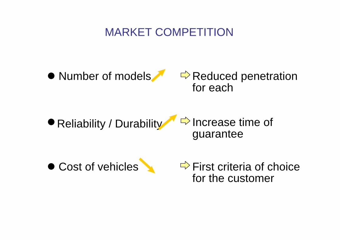
MARKET COMPETITION
Reliability / Durability
� Number of models Reduced penetrationfor each
� Increase time ofguarantee
� Cost of vehicles First criteria of choicefor the customer
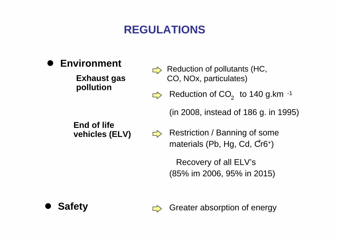
REGULATIONS
� EnvironmentExhaust gaspollution
Reduction of CO2 to 140 g.km -1
(in 2008, instead of 186 g. in 1995)
End of lifevehicles (ELV) Restriction / Banning of some
materials (Pb, Hg, Cd, Cr6+) +
Recovery of all ELV’s(85% im 2006, 95% in 2015)
� Safety Greater absorption of energy
Reduction of pollutants (HC, CO, NOx, particulates)
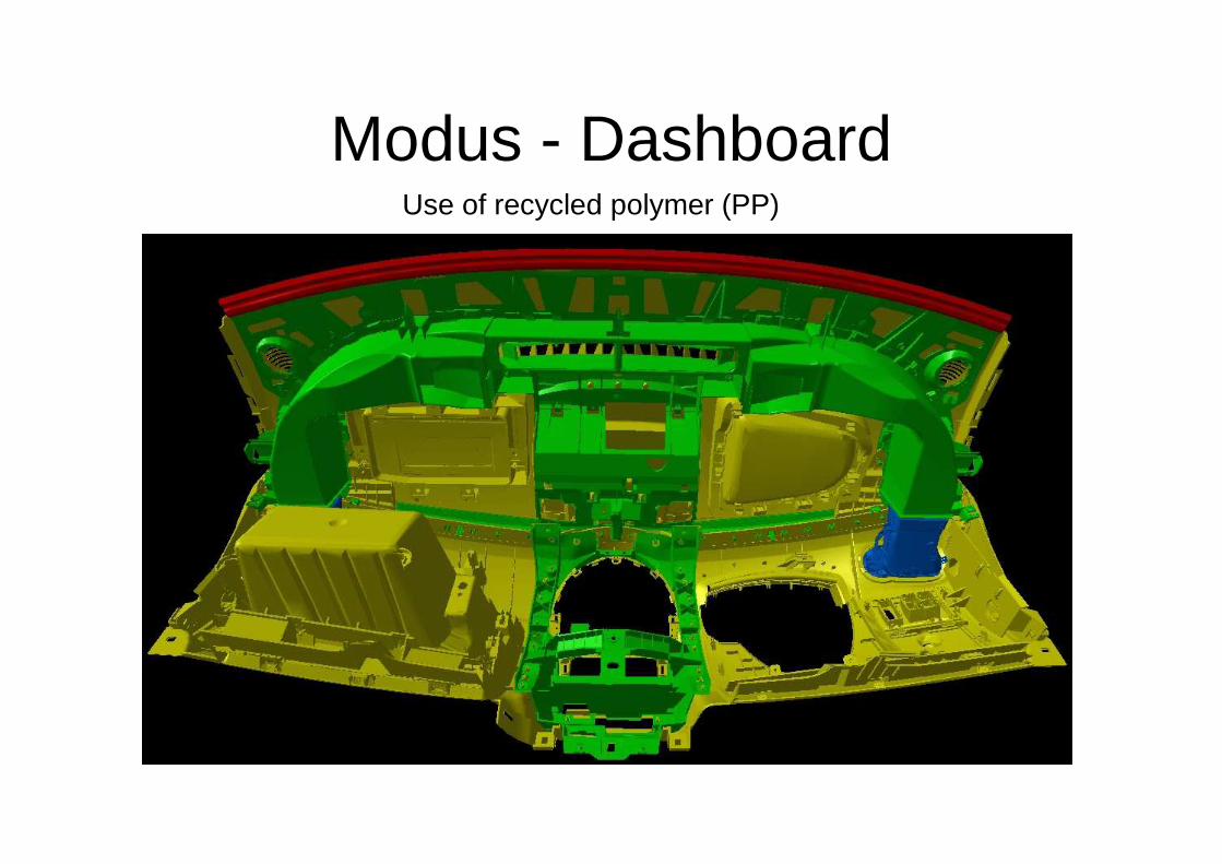
Modus - DashboardUse of recycled polymer (PP)
16
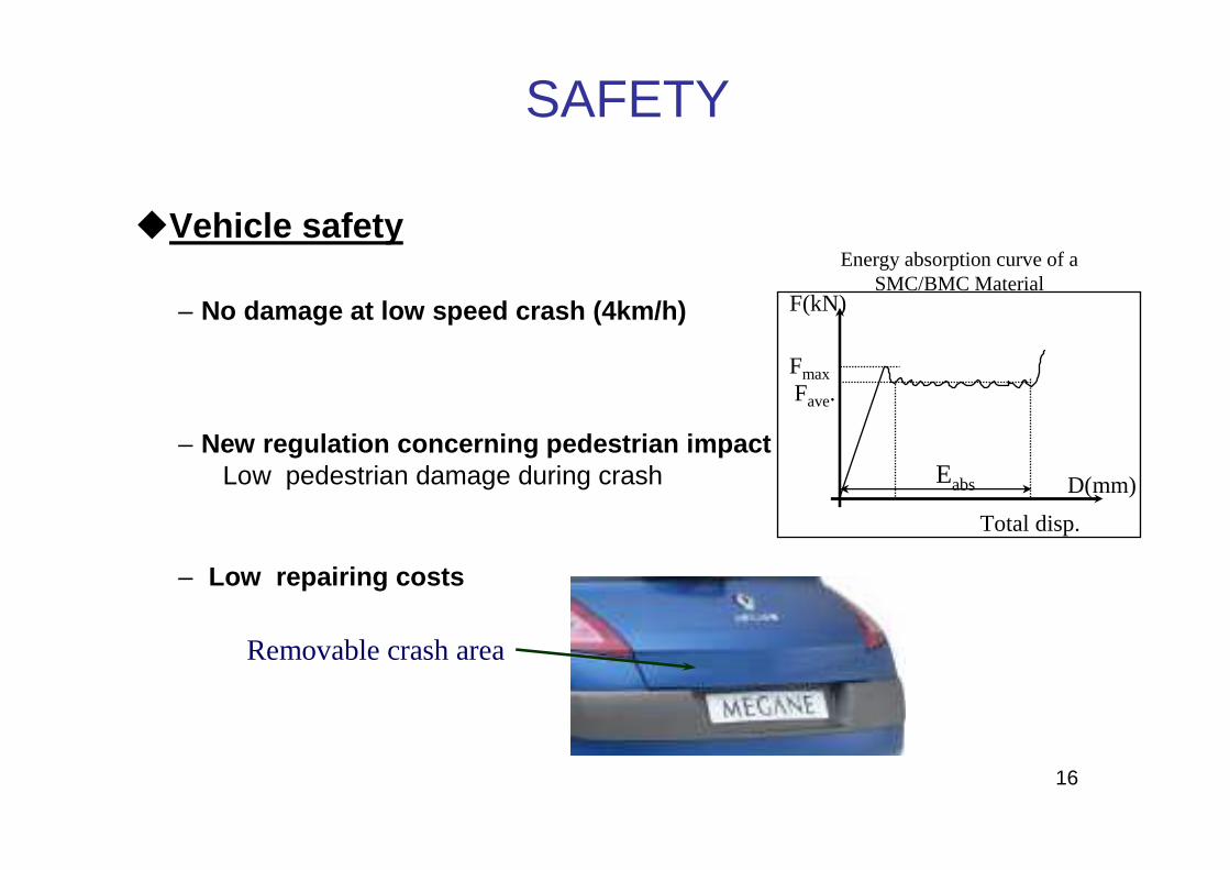
�Vehicle safety
– No damage at low speed crash (4km/h)
– New regulation concerning pedestrian impactLow pedestrian damage during crash
– Low repairing costs
SAFETY
Removable crash area
Eabs
Fmax
D(mm)
Fave.
Total disp.
Energy absorption curve of a SMC/BMC Material
F(kN)
Plan
1 - Automotive context
2 – Automotive project
3 – Hurdles associated with polymers andcomposites
4 – Examples of parts
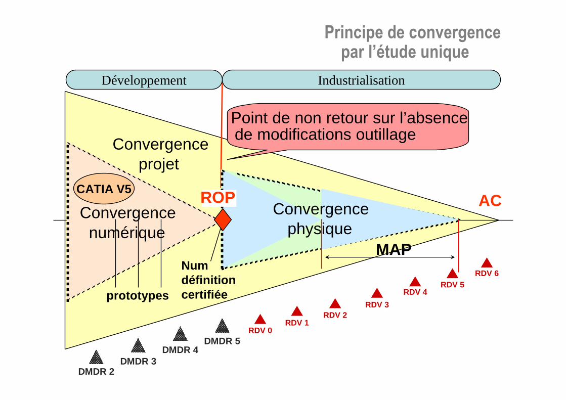
Convergenceprojet
Point de non retour sur l’absencede modifications outillage
Principe de convergence par l’étude unique
Développement Industrialisation
ACConvergencephysique
MAP
Convergencenumérique
CATIA V5
prototypes
Numdéfinition certifiée
ROP
DMDR 2DMDR 3
DMDR 4DMDR 5
RDV 0RDV 1
RDV 2RDV 3
RDV 4RDV 5
RDV 6
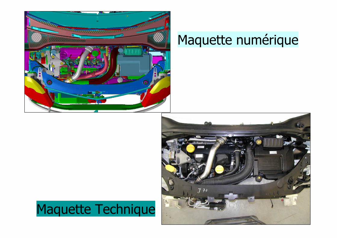
Illustration Physico-num
2
Maquette numérique
Maquette Technique
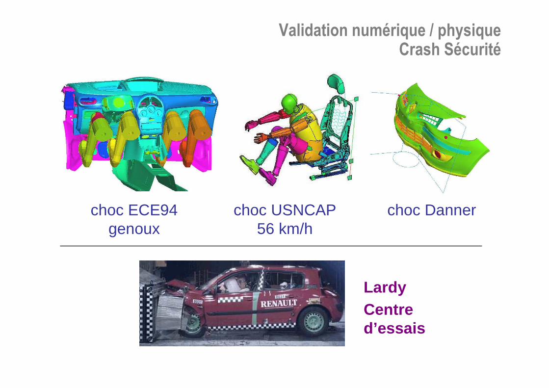
Validation numérique / physiqueCrash Sécurité
Centre d’essais
Lardy
choc ECE94 genoux
choc USNCAP56 km/h
choc Danner
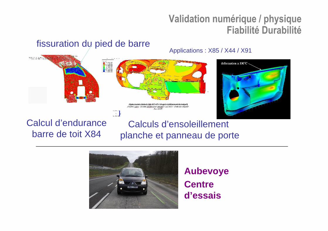
Calcul d’endurance barre de toit X84
Calculs d’ensoleillementplanche et panneau de porte
Applications : X85 / X44 / X91fissuration du pied de barre
Validation numérique / physiqueFiabilité Durabilité
Centre d’essais
Aubevoye
Bruit de roulementNASTRAN / AKUSMOD
Systèmes de retenuePAM-SAFE, MADYMO
Trains AV/AR-BerceauNASTRAN
SuspensionADAMS, MADA
Filtrationligne échappement
ADAMS, NASTRAN, GATEWAY,
ABAQUS
Comportement routier - FreinageMADA
Déformation d’ouvrantsNASTRAN, I-DEAS
Mécanismes ouvrantsRADIOSS, I-DEAS
Sièges et systèmes associés
NASTRAN, RADIOSS
Essuyage - DégivrageFLUENT
Superstructure / vibration CaisseNASTRAN, RADIOSS, PAMCRASH, FALANCS
Thermique habitacleAMESIM, FLUENT, INKA
Thermique / aéro sous capotI-DEAS TMG, FLUENT
Thermique moteurI-DEAS TMG, FLOW 3D
Perfo-ConsoSTAR-CD, AMESIM, WAVE
Aéroacoustique / Aéro externePOWERFLOW,FLUENT, SYSNOISE
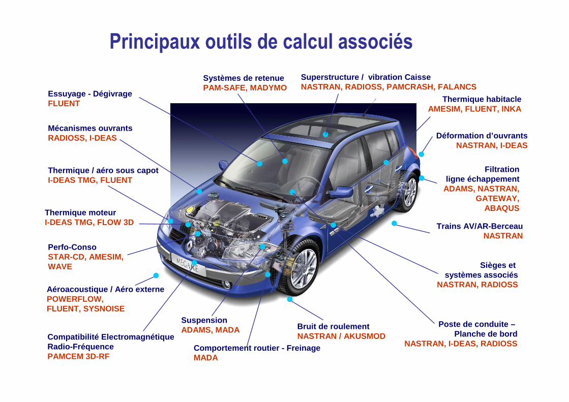
Principaux outils de calcul associés
Compatibilité ElectromagnétiqueRadio-FréquencePAMCEM 3D-RF
Poste de conduite –Planche de bord
NASTRAN, I-DEAS, RADIOSS
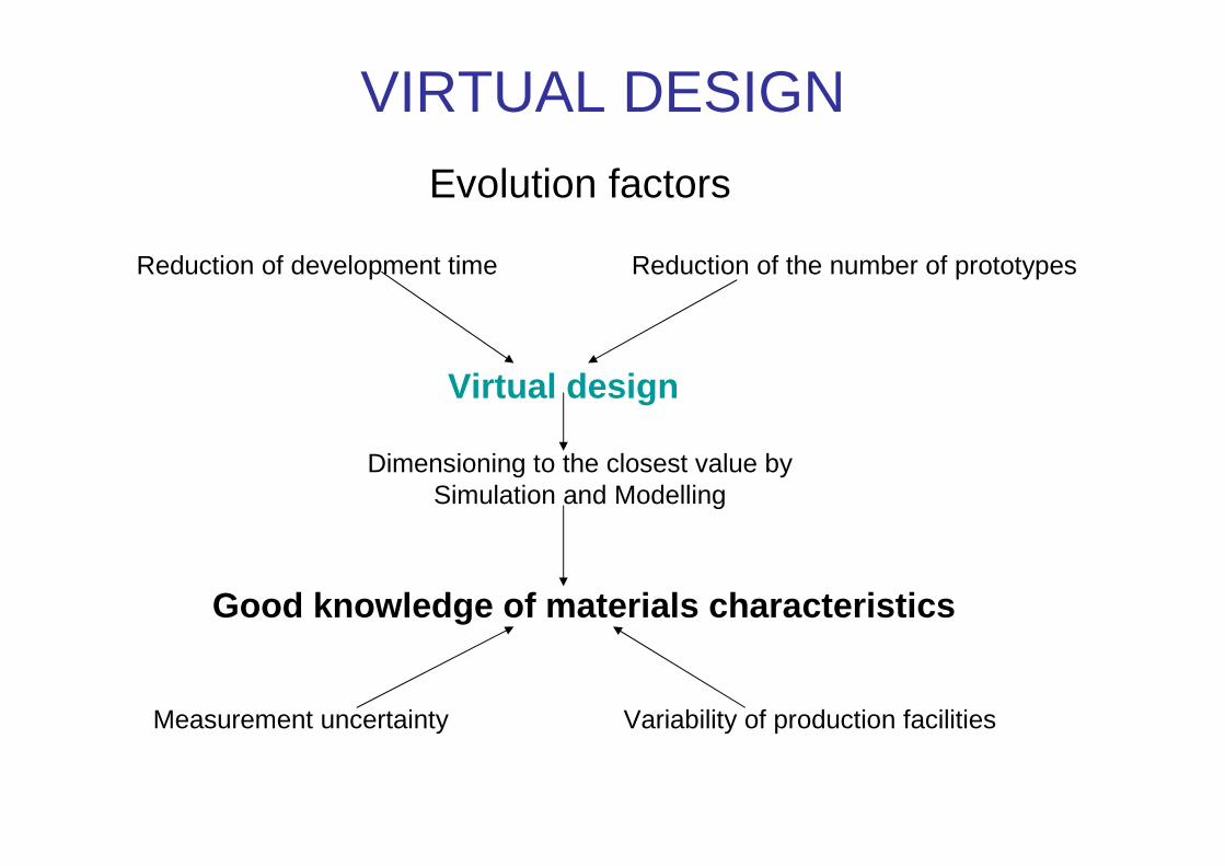
VIRTUAL DESIGN
Evolution factors
Reduction of development time Reduction of the number of prototypes
Virtual design
Dimensioning to the closest value bySimulation and Modelling
Good knowledge of materials characteristics
Measurement uncertainty Variability of production facilities
Developmentof materials
Shaping/Fabricationof the parts
Assembly ofthe vehicle
Recycling
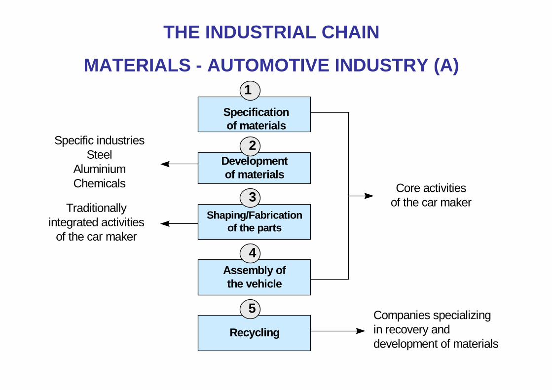
1
2
3
4
5
Specificationof materials
Specific industriesSteel
AluminiumChemicals
Traditionallyintegrated activities
of the car maker
Core activitiesof the car maker
Companies specializingin recovery anddevelopment of materials
THE INDUSTRIAL CHAIN
MATERIALS - AUTOMOTIVE INDUSTRY (A)
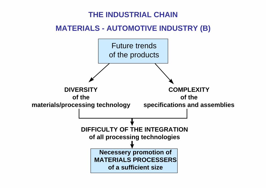
Future trendsof the products
DIVERSITYof the
materials/processing technology
COMPLEXITYof the
specifications and assemblies
DIFFICULTY OF THE INTEGRATIONof all processing technologies
Necessery promotion ofMATERIALS PROCESSERS
of a sufficient size
THE INDUSTRIAL CHAIN
MATERIALS - AUTOMOTIVE INDUSTRY (B)
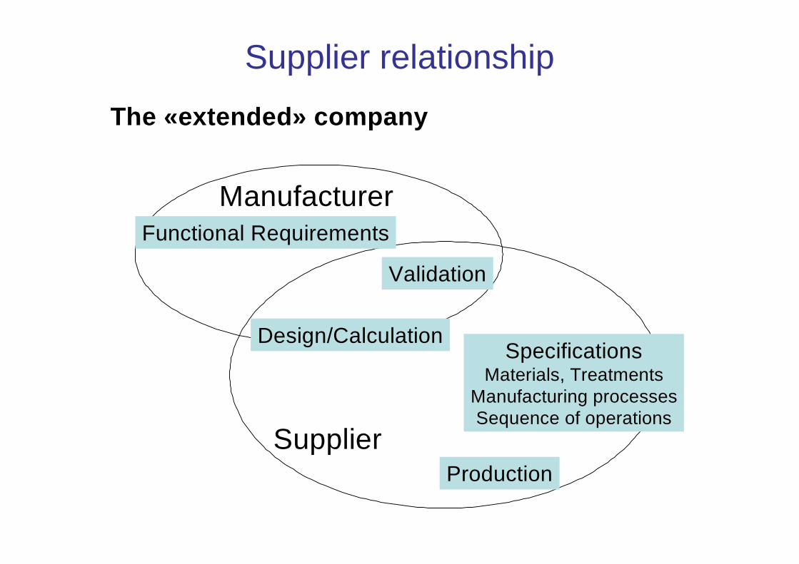
Supplier relationship
The «extended» company
Manufacturer
Supplier
Functional Requirements
Validation
Design/Calculation
Production
SpecificationsMaterials, Treatments
Manufacturing processesSequence of operations
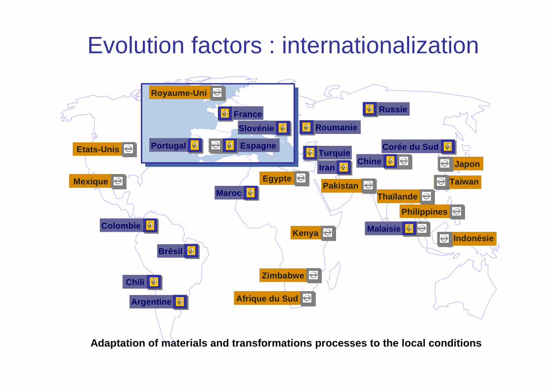
Evolution factors : internationalization
Adaptation of materials and transformations process es to the local conditions
MalaisieColombie
Brésil
Chili
Argentine
Roumanie
Maroc
Turquie
Russie
ChineIran
Corée du SudEtats-Unis
Mexique Egypte
Kenya
Zimbabwe
Afrique du Sud
Thaïlande
Philippines
Indonésie
Japon
TaiwanPakistan
Royaume-Uni
Portugal Espagne
France
Slovénie
Plan
1 - Automotive context
2 – Automotive project
3 – Hurdles associated withpolymers and composites
4 – Examples of parts
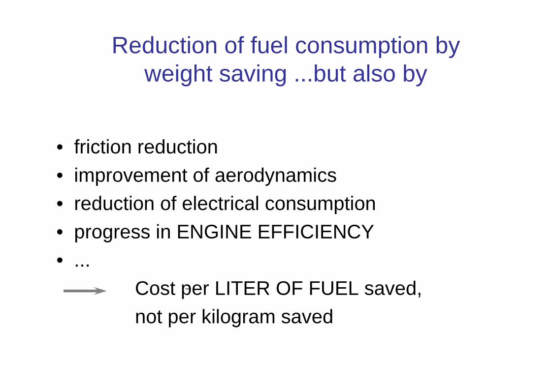
Reduction of fuel consumption by weight saving ...but also by
• friction reduction• improvement of aerodynamics• reduction of electrical consumption• progress in ENGINE EFFICIENCY• ...
Cost per LITER OF FUEL saved,not per kilogram saved
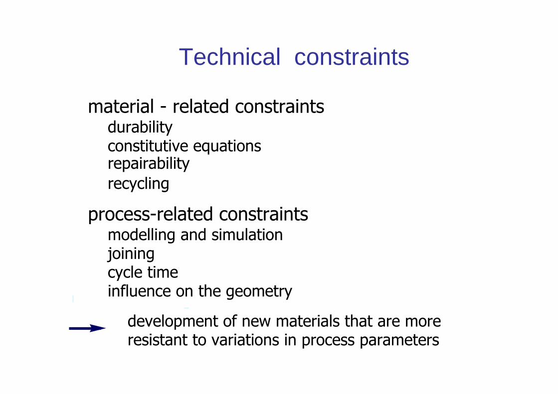
Technical constraints
material - related constraintsdurabilityconstitutive equationsrepairabilityrecycling
process-related constraintsmodelling and simulationjoiningcycle timeinfluence on the geometry
development of new materials that are moreresistant to variations in process parameters
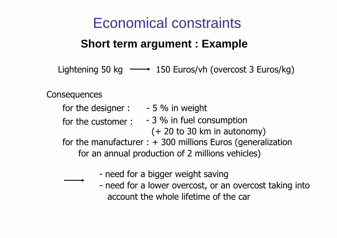
Economical constraintsShort term argument : Example
Lightening 50 kg 150 Euros/vh (overcost 3 Euros/kg)
Consequences
for the designer : - 5 % in weight
for the customer : - 3 % in fuel consumption(+ 20 to 30 km in autonomy)
for the manufacturer : + 300 millions Euros (generalization
for an annual production of 2 millions vehicles)
- need for a bigger weight saving
- need for a lower overcost, or an overcost taking into
account the whole lifetime of the car
Technical constraintsTechnical constraints
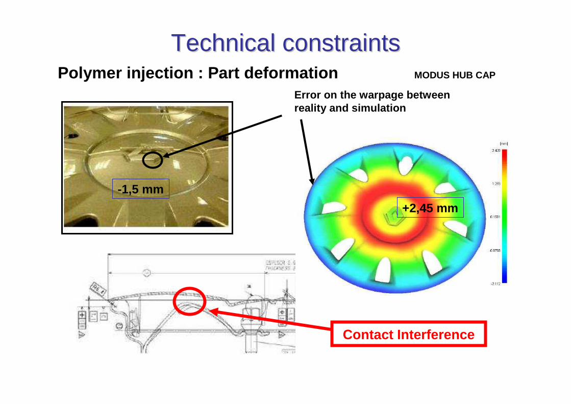
Error on the warpage between reality and simulation
+2,45 mm
-1,5 mm
Contact Interference
Polymer injection : Part deformation MODUS HUB CAP
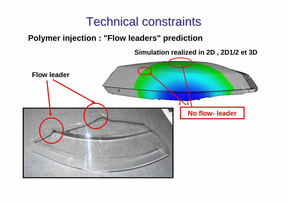
TechnicalTechnical constraintsconstraints
Flow leader
No flow- leader
Simulation realized in 2D , 2D1/2 et 3D
Polymer injection : "Flow leaders" prediction

Technical constraintsTechnical constraints
Shrinkage marksShrinkage
Deformation
Polymer injection : Shrink - marks prediction
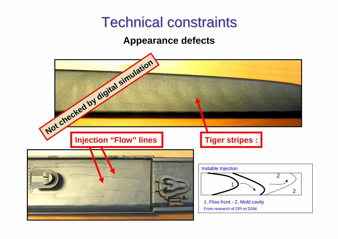
Technical constraintsTechnical constraints
Tiger stripes :
Instable Injection
From research of DPI et DSM.
1. Flow front - 2. Mold cavity
1
2
2
Injection “Flow” linesNot c
hecked by digital sim
ulation
Appearance defects
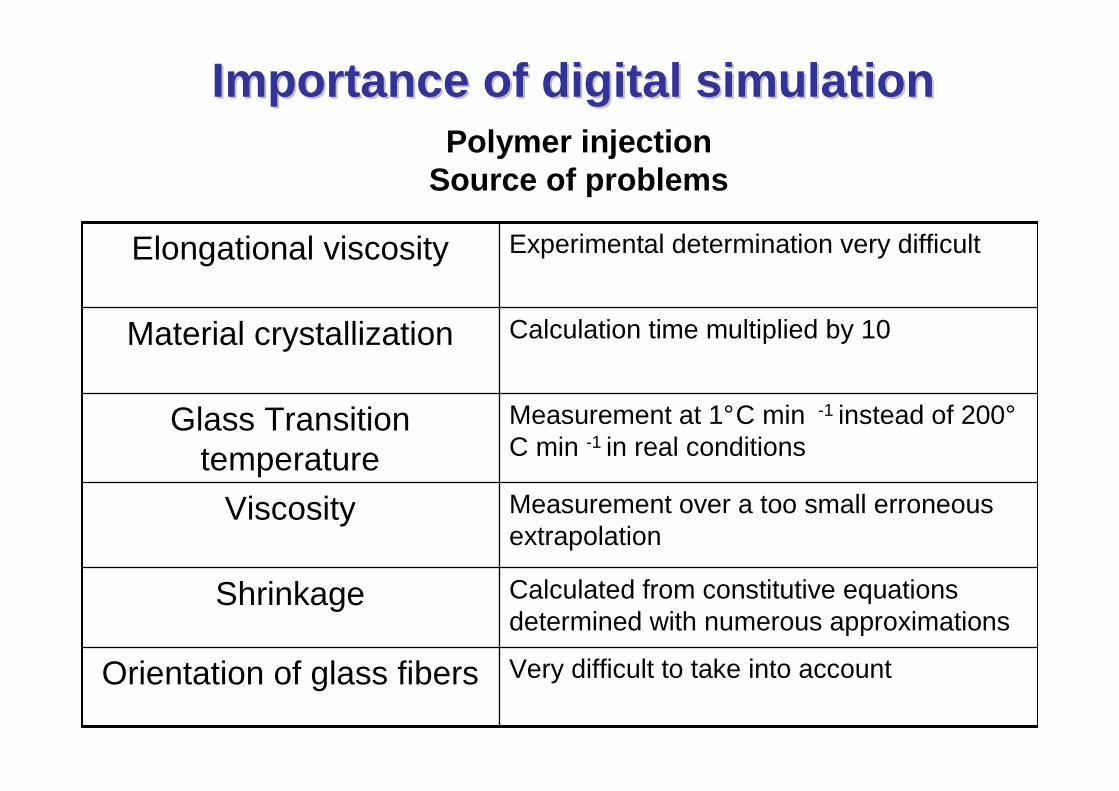
Importance of digital simulationImportance of digital simulation
Very difficult to take into accountOrientation of glass fibers
Calculated from constitutive equations determined with numerous approximations
Shrinkage
Measurement over a too small erroneous extrapolation
Viscosity
Measurement at 1°C min -1 instead of 200°C min -1 in real conditions
Glass Transition temperature
Calculation time multiplied by 10Material crystallization
Experimental determination very difficultElongational viscosity
Polymer injectionSource of problems
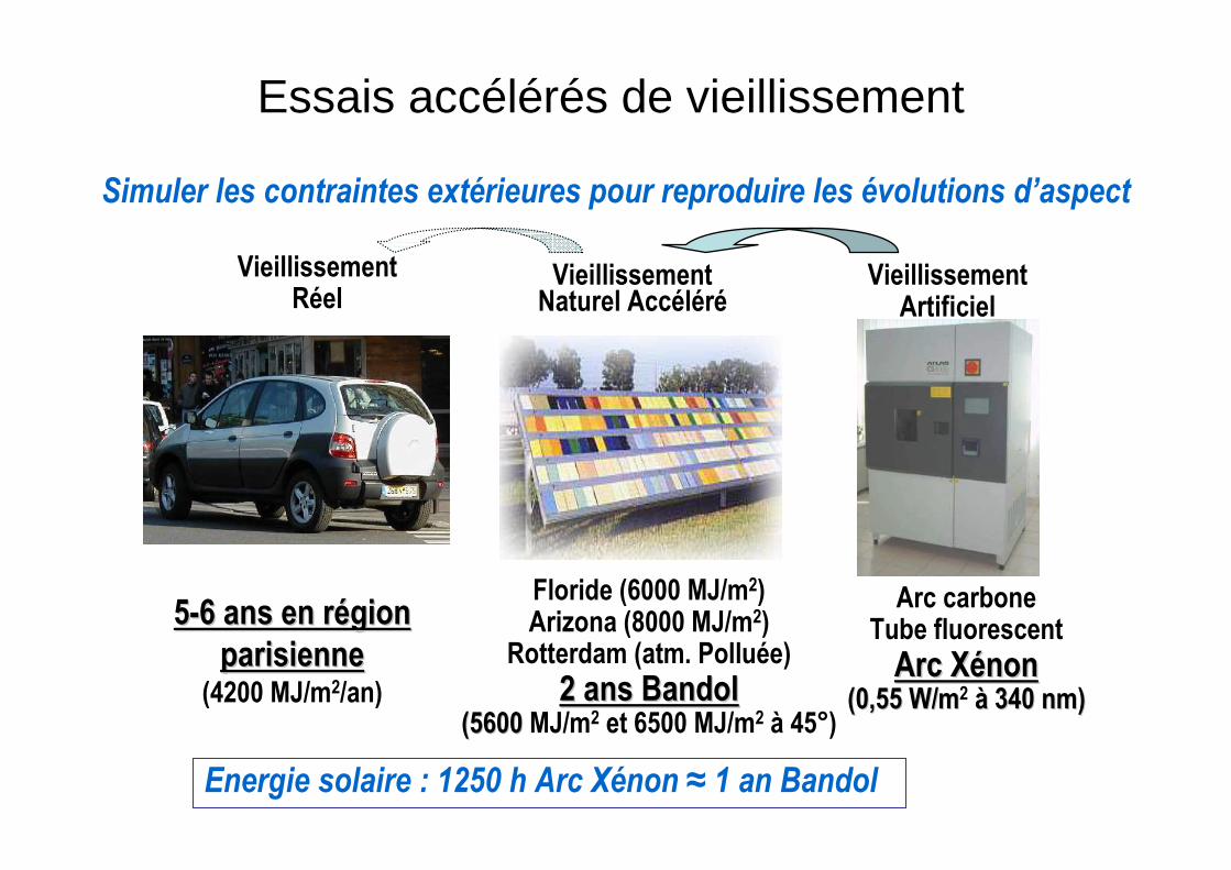
Simuler les contraintes extérieures pour reproduire les évolutions d’aspect
VieillissementArtificiel
VieillissementNaturel Accéléré
VieillissementRéel
55--6 ans en r6 ans en réégion gion
parisienneparisienne(4200 MJ/m2/an)
Floride (6000 MJ/m2)Arizona (8000 MJ/m2)
Rotterdam (atm. Polluée)
2 ans Bandol 2 ans Bandol (5600 (5600 MJ/m2 et 6500 MJ/m2 à 45°)
Arc carboneTube fluorescent
Arc XArc Xéénonnon(0,55 W/m(0,55 W/m2 àà 340 nm)340 nm)
Energie solaire : 1250 h Arc Xénon ≈ 1 an Bandol
Essais accélérés de vieillissement
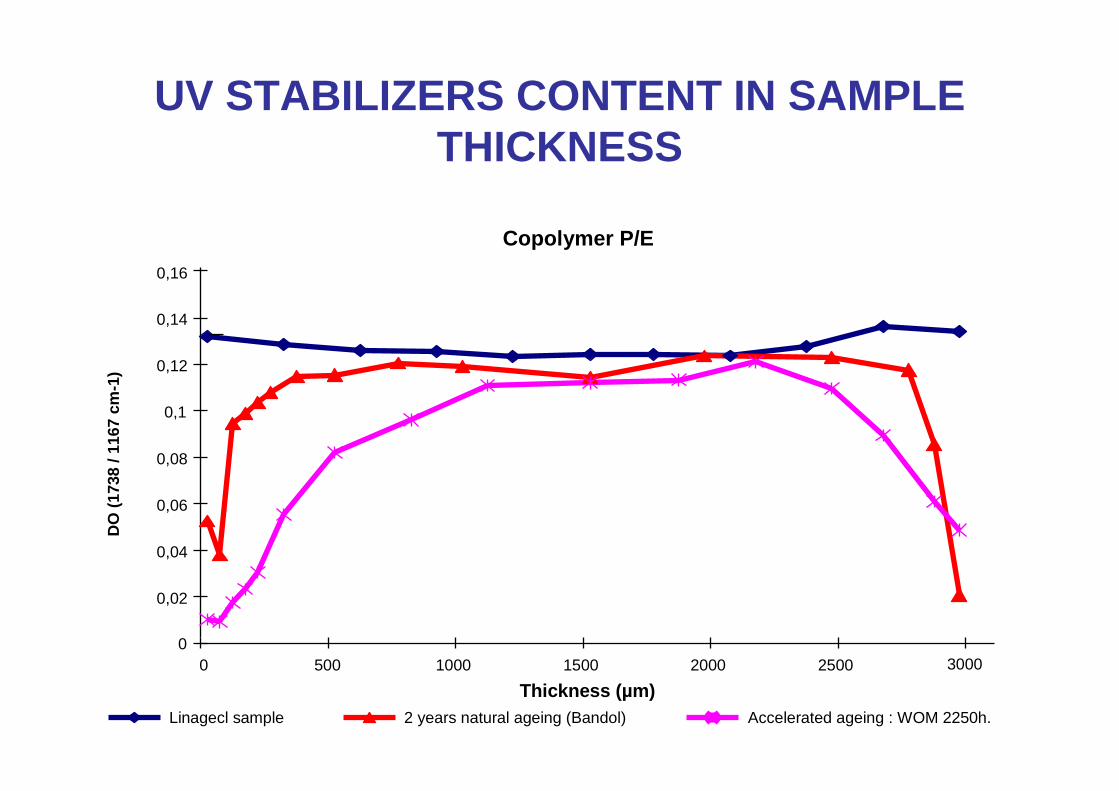
UV STABILIZERS CONTENT IN SAMPLE THICKNESS
Thickness (µm)Linagecl sample 2 years natural ageing (Bandol) Accelerated ageing : WOM 2250h.
0
0,02
0,04
0,06
0,08
0,1
0,12
0,14
0,16
0 500 1000 1500 2000 2500 3000
DO
(17
38 /
1167
cm
-1)
Copolymer P/E
Plan
1 - Automotive context
2 – Automotive project
3 – Hurdles associated with polymers andcomposites
4 – Examples of parts
Composite material parts(Renault cars)
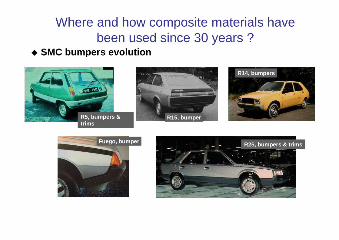
Where and how composite materials have been used since 30 years ?
R15, bumperR5, bumpers & trims
R14, bumpers
Fuego, bumper R25, bumpers & trims
� SMC bumpers evolution
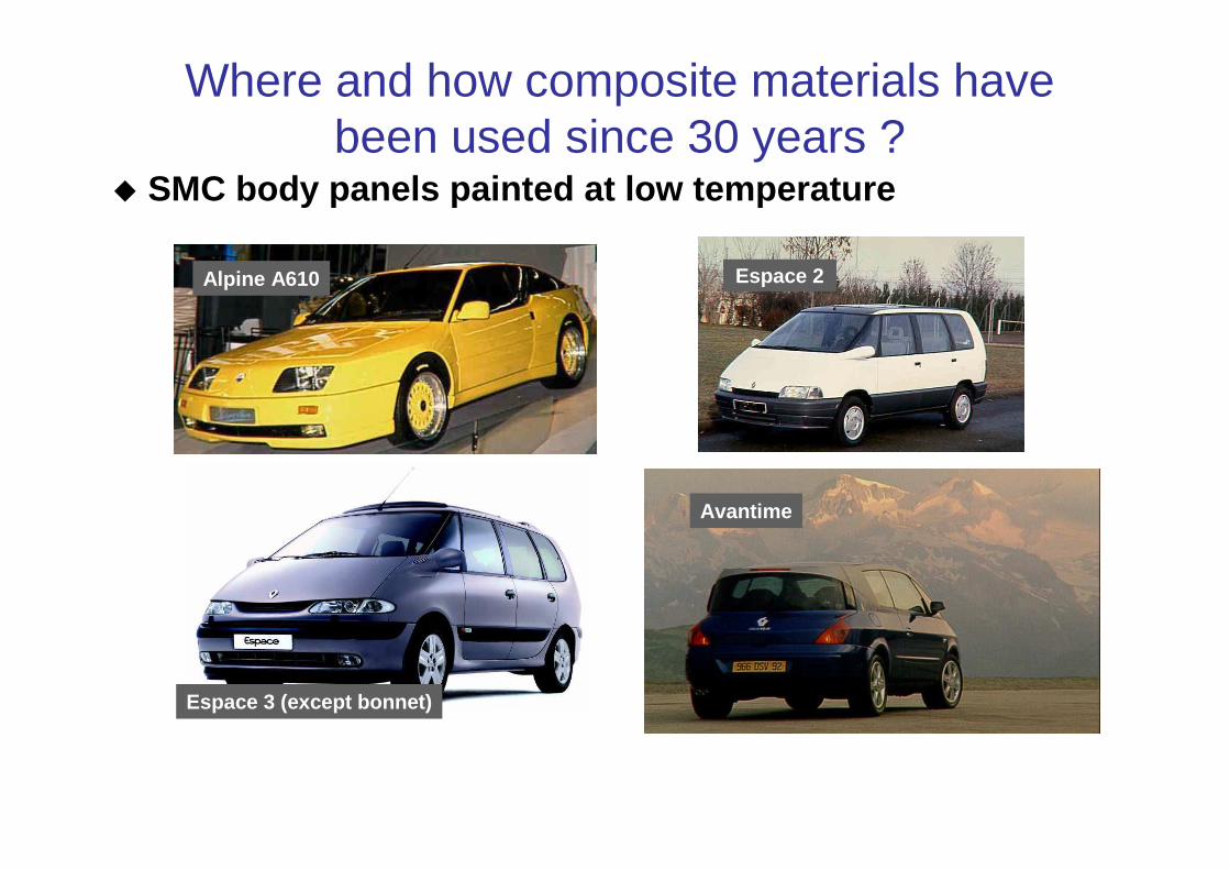
Where and how composite materials have been used since 30 years ?
Espace 2
Avantime
Espace 3 (except bonnet)
Alpine A610
� SMC body panels painted at low temperature
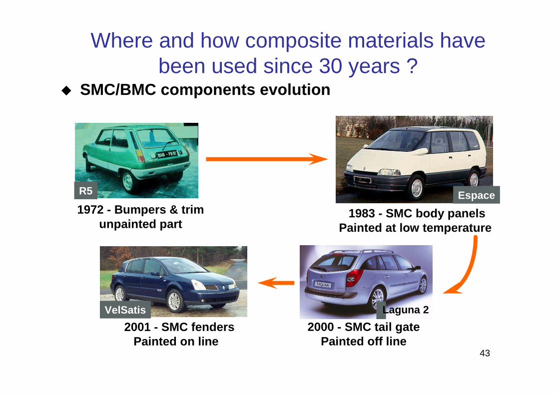
43
1983 - SMC body panelsPainted at low temperature
Espace
2000 - SMC tail gatePainted off line
2001 - SMC fendersPainted on line
VelSatis
1972 - Bumpers & trimunpainted part
R5
� SMC/BMC components evolution
Where and how composite materials have been used since 30 years ?
Laguna 2

Where and how composite materials have been used since 30 years ?
Trafic rear spring leaf :- Weight saving : from 15 to 20 kg,- Same cost / double steel spring leafs- pre-preg epoxy glass LF (50/50 vol).
New transversal front suspension :- epoxy – glass fabric,- “High speed” RTM.
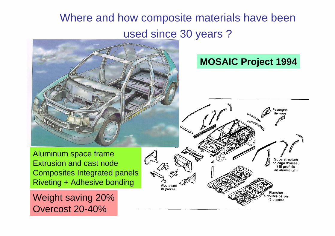
MOSAIC Project 1994
Aluminum space frameExtrusion and cast nodeComposites Integrated panelsRiveting + Adhesive bonding
Weight saving 20%Overcost 20-40%
Where and how composite materials have been
used since 30 years ?
46
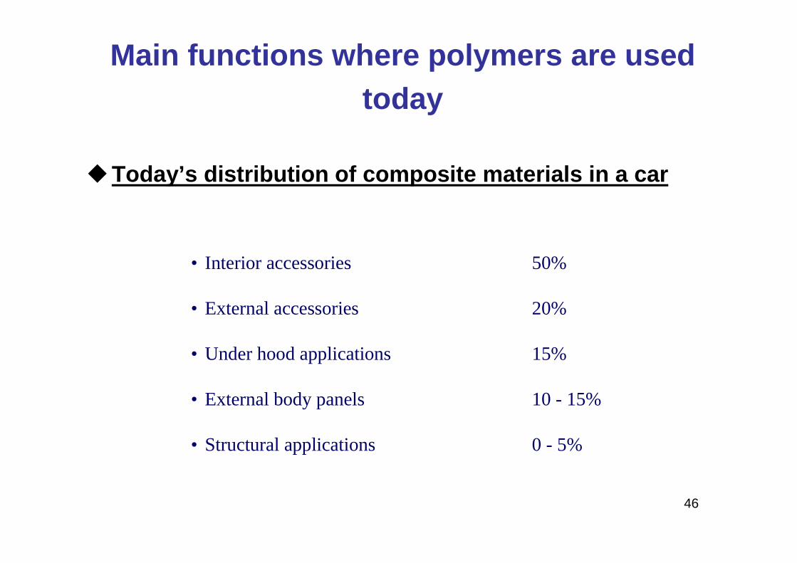
�Today’s distribution of composite materials in a ca r
• Interior accessories 50%
• External accessories 20%
• Under hood applications 15%
• External body panels 10 - 15%
• Structural applications 0 - 5%
Main functions where polymers are used today
47
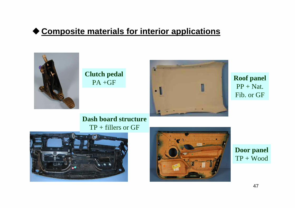
�Composite materials for interior applications
Dash board structureTP + fillers or GF
Clutch pedalPA +GF
Roof panelPP + Nat. Fib. or GF
Door panelTP + Wood
48
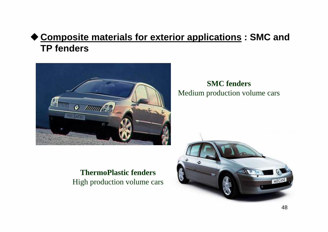
SMC fendersMedium production volume cars
ThermoPlastic fendersHigh production volume cars
�Composite materials for exterior applications : SMC and TP fenders
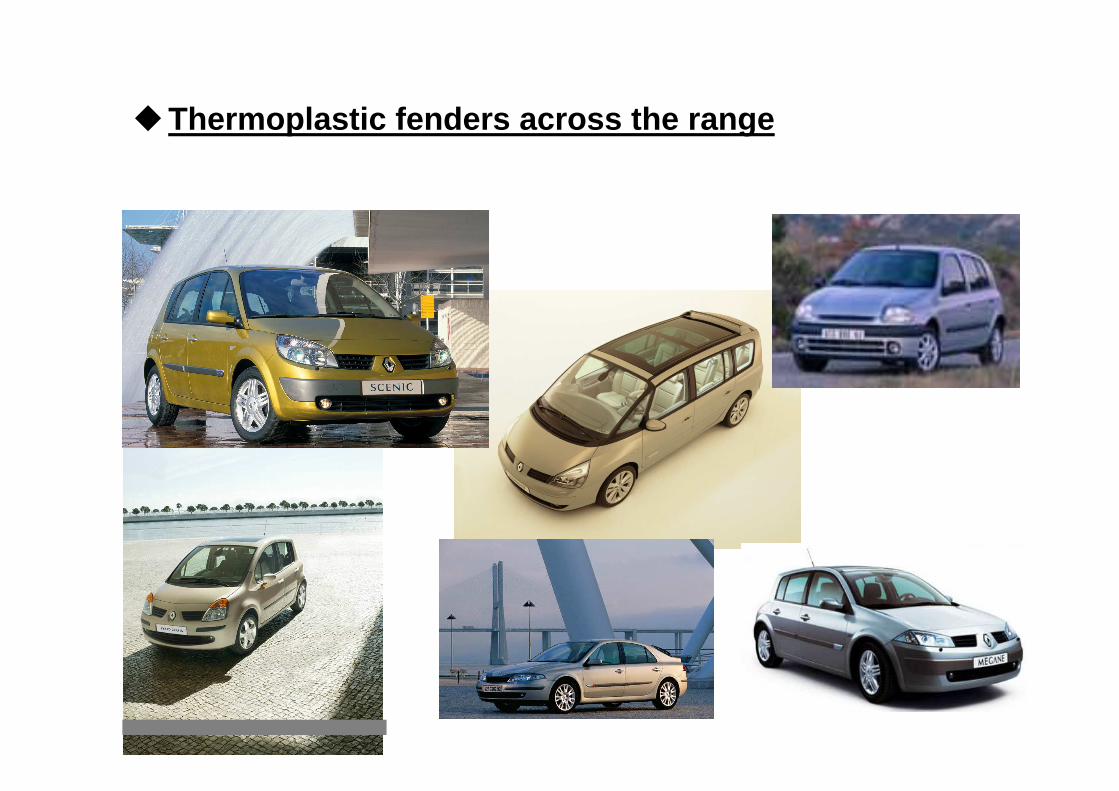
�Thermoplastic fenders across the range
50
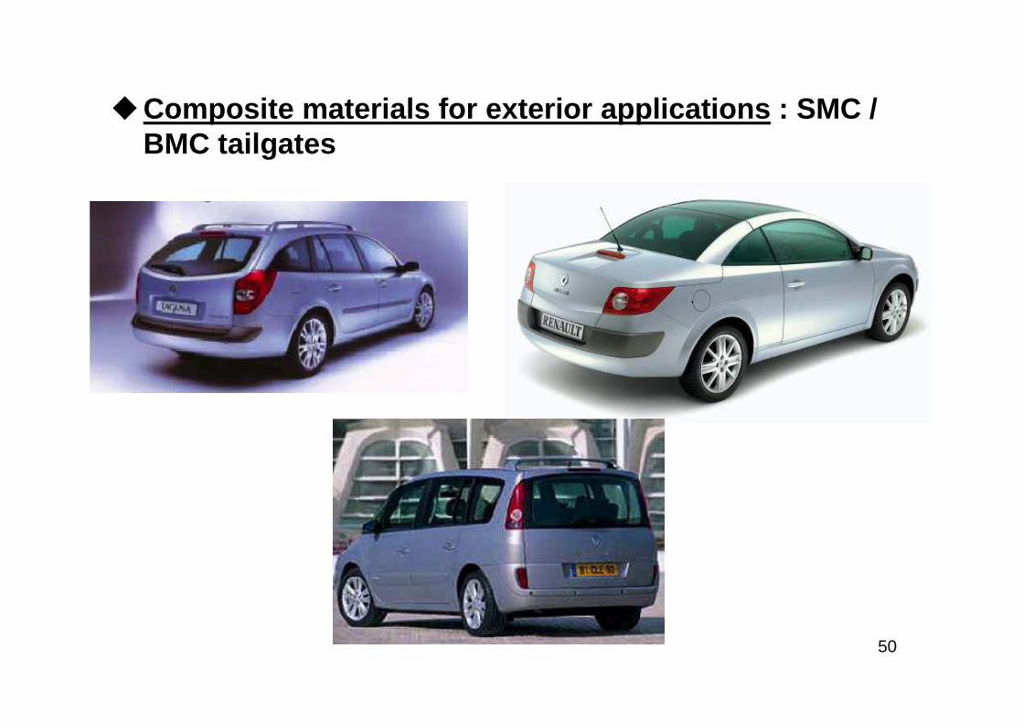
�Composite materials for exterior applications : SMC / BMC tailgates
Megane cc
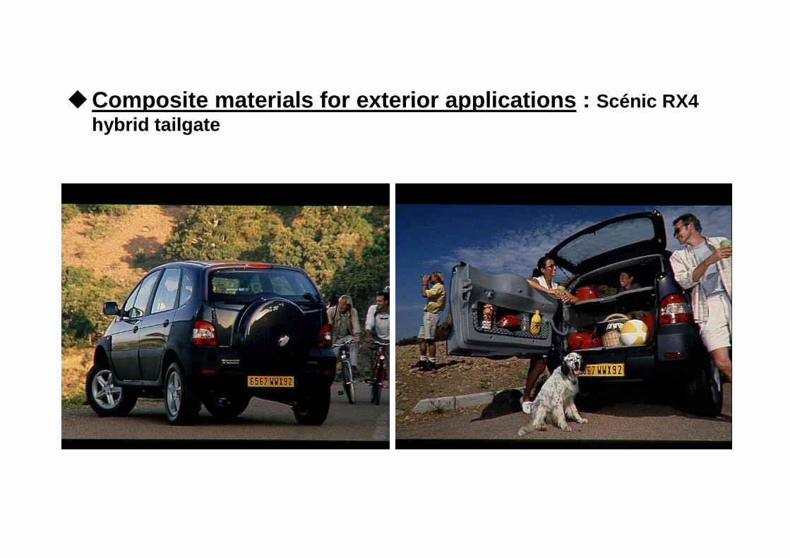
�Composite materials for exterior applications : Scénic RX4 hybrid tailgate
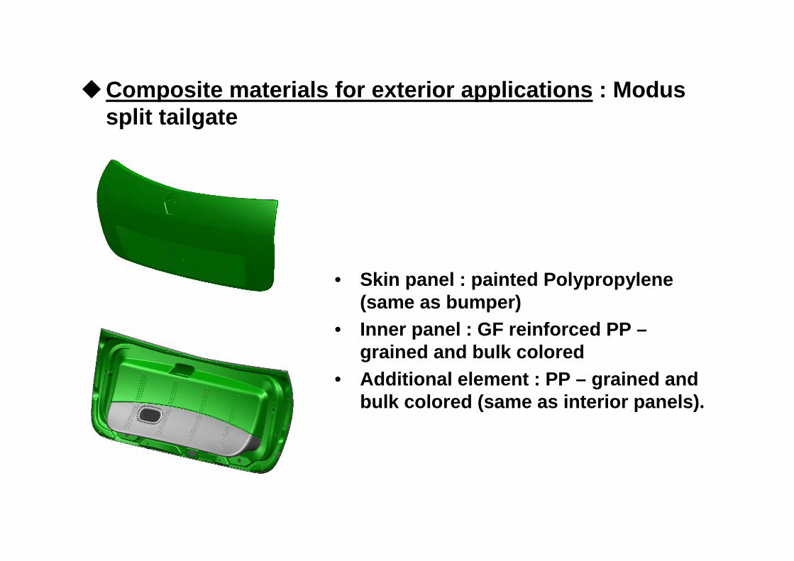
• Skin panel : painted Polypropylene(same as bumper)
• Inner panel : GF reinforced PP –grained and bulk colored
• Additional element : PP – grained andbulk colored (same as interior panels).
�Composite materials for exterior applications : Modus split tailgate
53
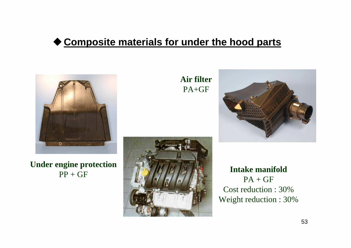
�Composite materials for under the hood parts
Air filterPA+GF
Under engine protectionPP + GF
Intake manifoldPA + GF
Cost reduction : 30%Weight reduction : 30%
54
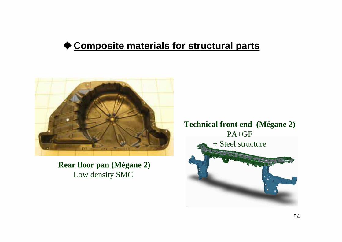
�Composite materials for structural parts
Technical front end (Mégane 2)PA+GF
+ Steel structure
Rear floor pan (Mégane 2)Low density SMC
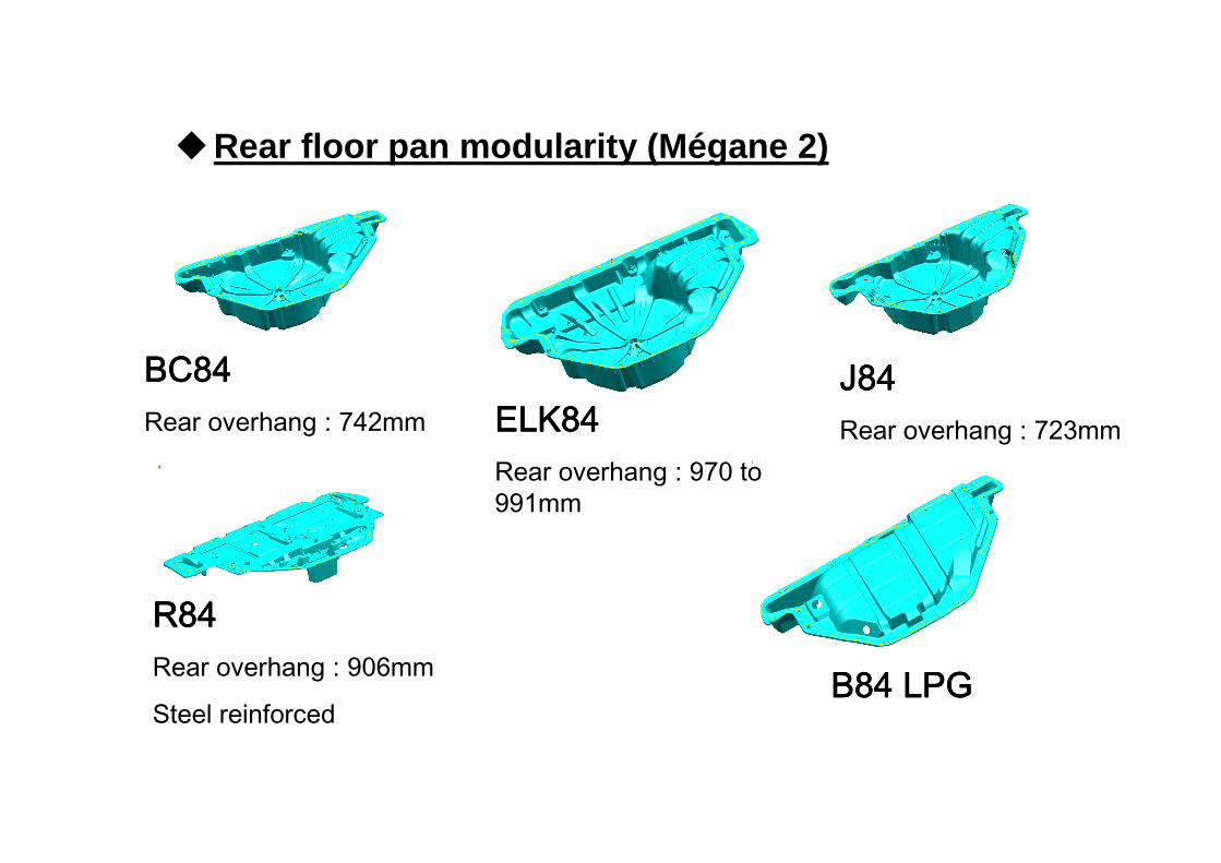
BC84BC84BC84BC84Rear overhang : 742mm
J84J84J84J84Rear overhang : 723mm
R84R84R84R84Rear overhang : 906mm
Steel reinforcedB84 LPGB84 LPGB84 LPGB84 LPG
ELK84ELK84ELK84ELK84Rear overhang : 970 to 991mm
�Rear floor pan modularity (Mégane 2)
56
�New composite materials : Some examples
– Composite materials reinforced with nano fillersIntroduction of mineral nano fillers or carbon nano tubes in TP matrix
Semi structural applications (body panels, under the hood parts)
– Composite materials reinforced with natural fibersIntroduction of natural fibres (Hemp, flax ...) in TP and thermoset matrix
Semi structural applications (Interior applications)
– Composite materials reinforced with carbon fibersIntroduction of short carbon fibres, or carbon fibre fabrics
Structural parts (floor pans, cross beams, Body In White parts …)Semi structural parts (openings)
Current developments going on
57
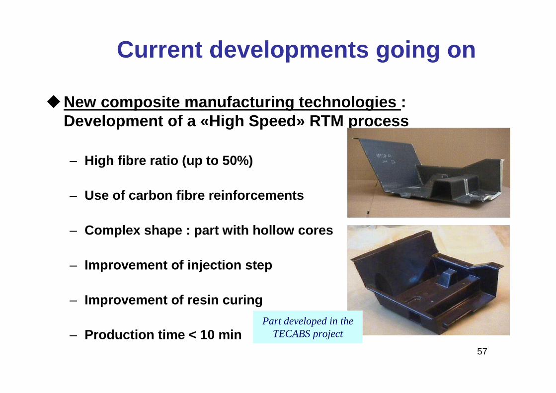
�New composite manufacturing technologies : Development of a «High Speed» RTM process
– High fibre ratio (up to 50%)
– Use of carbon fibre reinforcements
– Complex shape : part with hollow cores
– Improvement of injection step
– Improvement of resin curing
– Production time < 10 min
Current developments going on
Part developed in the TECABS project
58
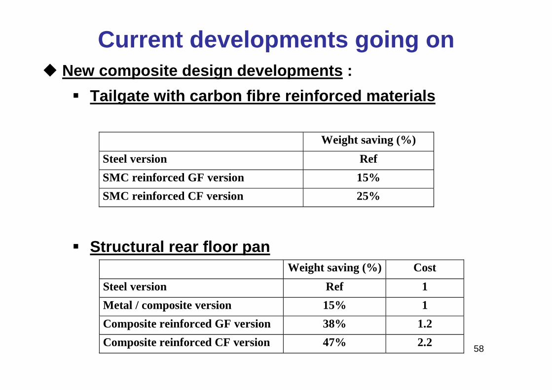
� Tailgate with carbon fibre reinforced materials
� Structural rear floor pan
Weight saving (%)
Steel version Ref
SMC reinforced GF version 15%
SMC reinforced CF version 25%
Weight saving (%) Cost
Steel version Ref 1
Metal / composite version 15% 1
Composite reinforced GF version 38% 1.2
Composite reinforced CF version 47% 2.2
Current developments going on� New composite design developments :
Thermoplastic fenders(Renault cars)
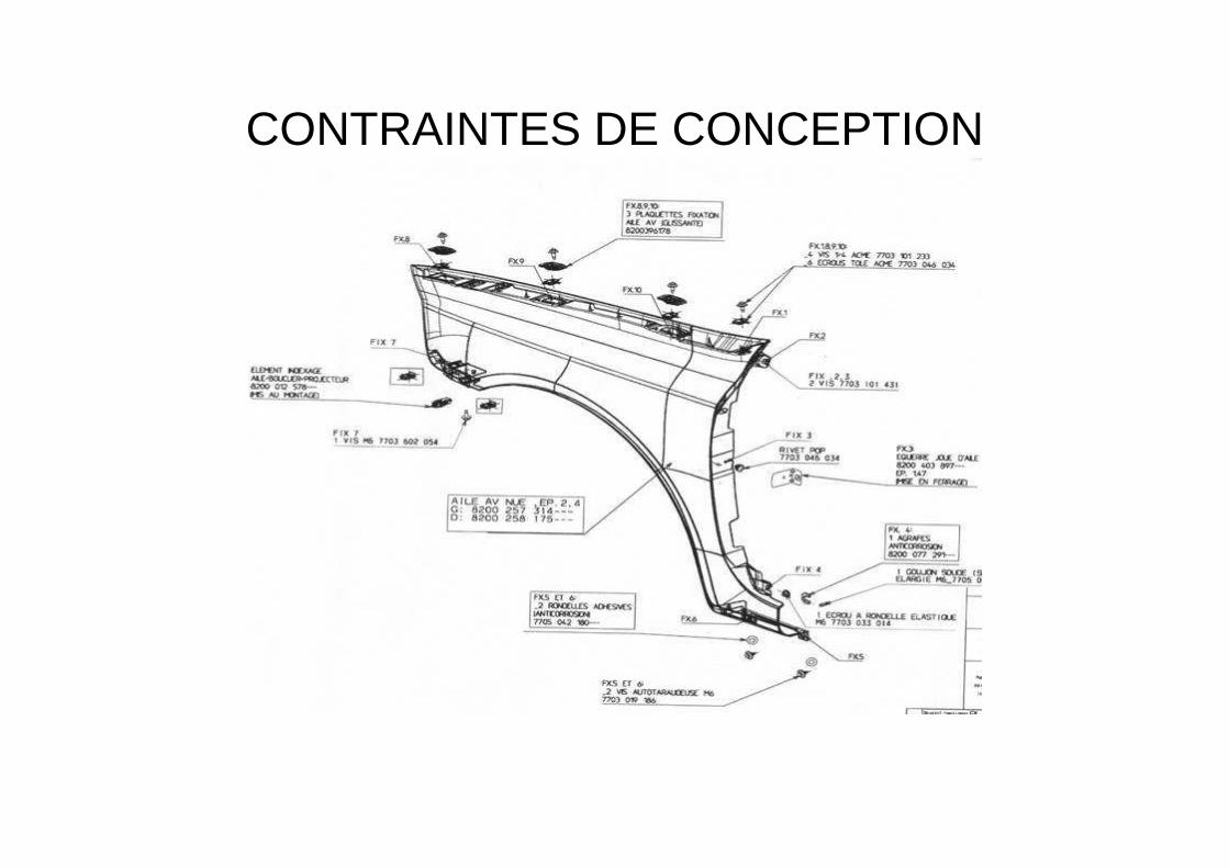
CONTRAINTES DE CONCEPTION
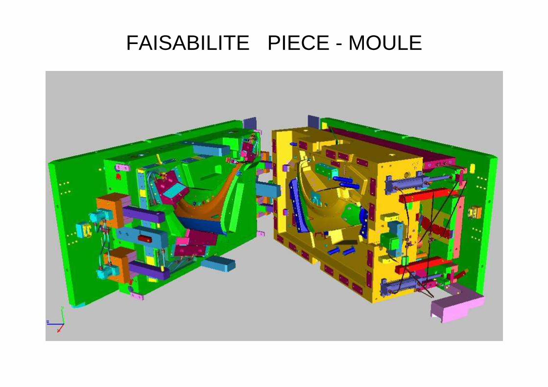
FAISABILITE PIECE - MOULE
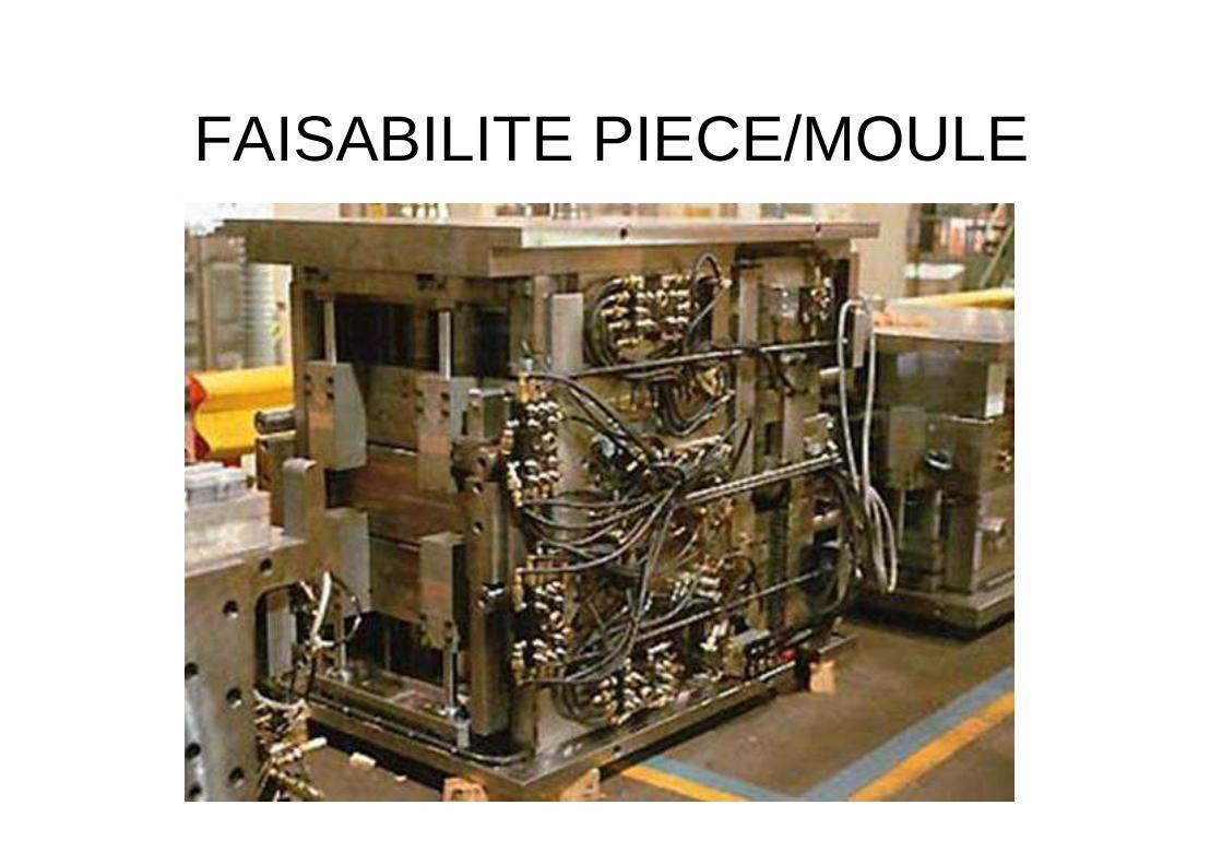
FAISABILITE PIECE/MOULE
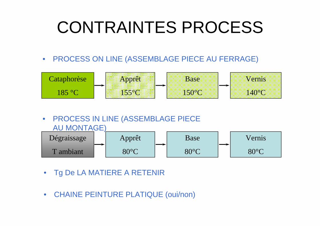
CONTRAINTES PROCESS
Cataphorèse
185 °C
Apprêt
155°C
Base
150°C
Vernis
140°C
Dégraissage
T ambiant
Apprêt
80°C
Base
80°C
Vernis
80°C
• PROCESS ON LINE (ASSEMBLAGE PIECE AU FERRAGE)
• PROCESS IN LINE (ASSEMBLAGE PIECE AU MONTAGE)
• Tg De LA MATIERE A RETENIR
• CHAINE PEINTURE PLATIQUE (oui/non)
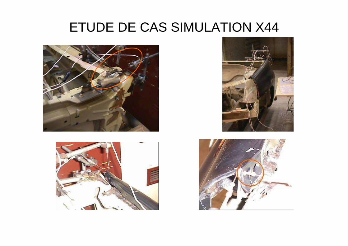
ETUDE DE CAS SIMULATION X44
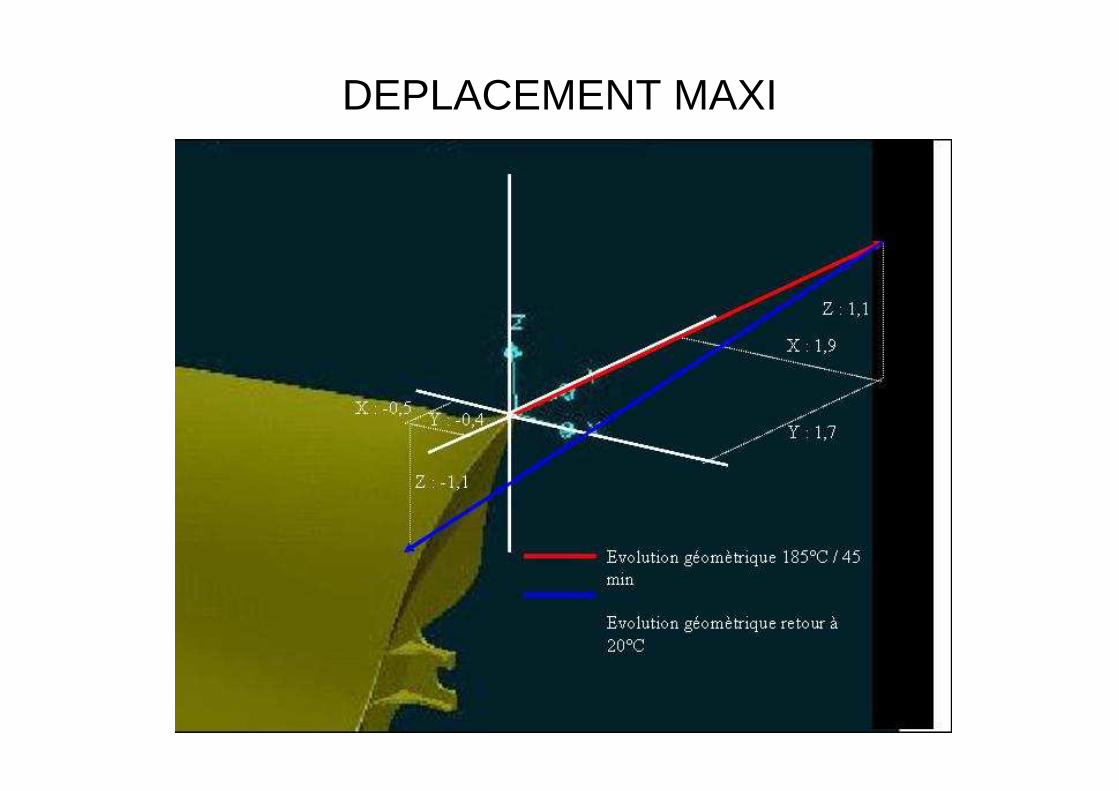
DEPLACEMENT MAXI
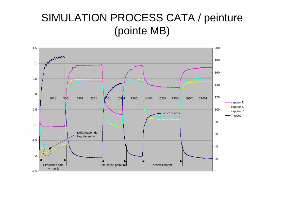
SIMULATION PROCESS CATA / peinture (pointe MB)
-2,5
-2
-1,5
-1
-0,5
0
0,5
1
1,5
1 1801 3601 5401 7201 9001 10801 12601 14401 16201 18001 19801 21601
0
20
40
60
80
100
120
140
160
180
200
capteur Z
capteur X
capteur Y
T° pièce
Simulation cata + mastic
Simulation peinture ensoleillement
Déformation de l'agrafe sapin
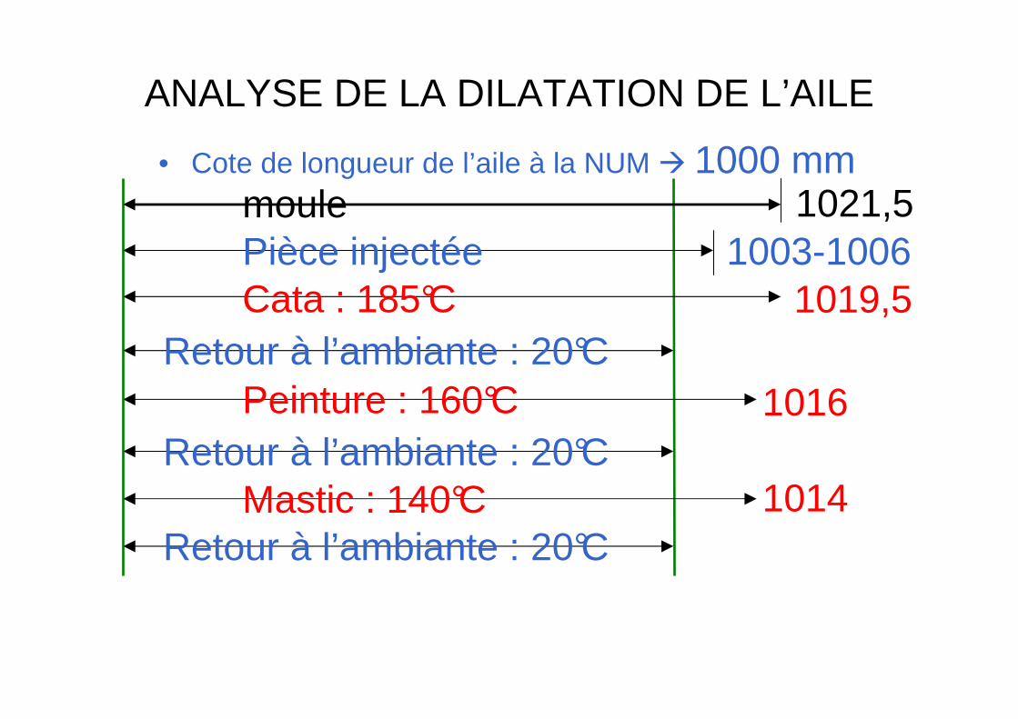
ANALYSE DE LA DILATATION DE L’AILE
• Cote de longueur de l’aile à la NUM � 1000 mm1021,5moule
Pièce injectée 1003-1006Cata : 185°C 1019,5
Retour à l’ambiante : 20°CPeinture : 160°C 1016
Retour à l’ambiante : 20°CMastic : 140°C 1014
Retour à l’ambiante : 20°C
LA TRANSFORMATION
NORYL MOULE
PRESSE
T°
V
P
t
T°
PIECE
GEOMETRIE ASPECTPEINTURE
CHOC
MONTAGE
résultatvariable
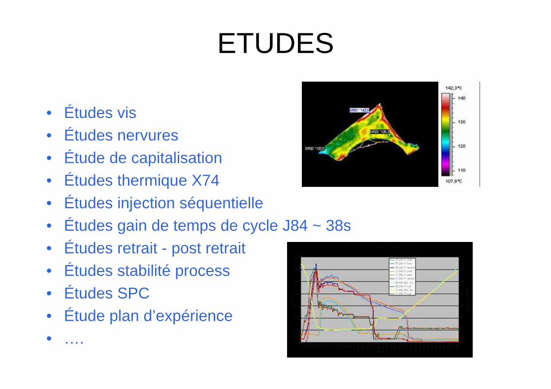
ETUDES
• Études vis• Études nervures• Étude de capitalisation• Études thermique X74• Études injection séquentielle• Études gain de temps de cycle J84 ~ 38s• Études retrait - post retrait• Études stabilité process• Études SPC• Étude plan d’expérience• ….
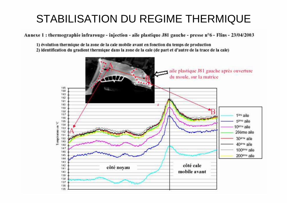
STABILISATION DU REGIME THERMIQUE
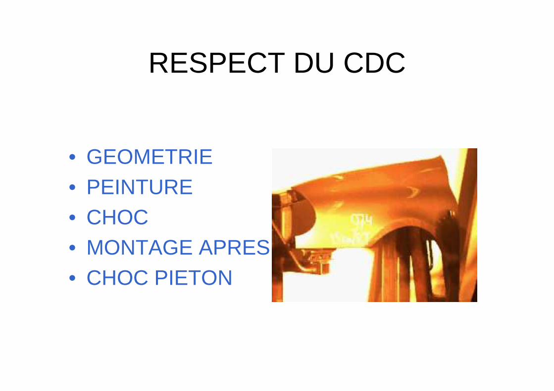
RESPECT DU CDC
• GEOMETRIE• PEINTURE• CHOC• MONTAGE APRES VENTE• CHOC PIETON
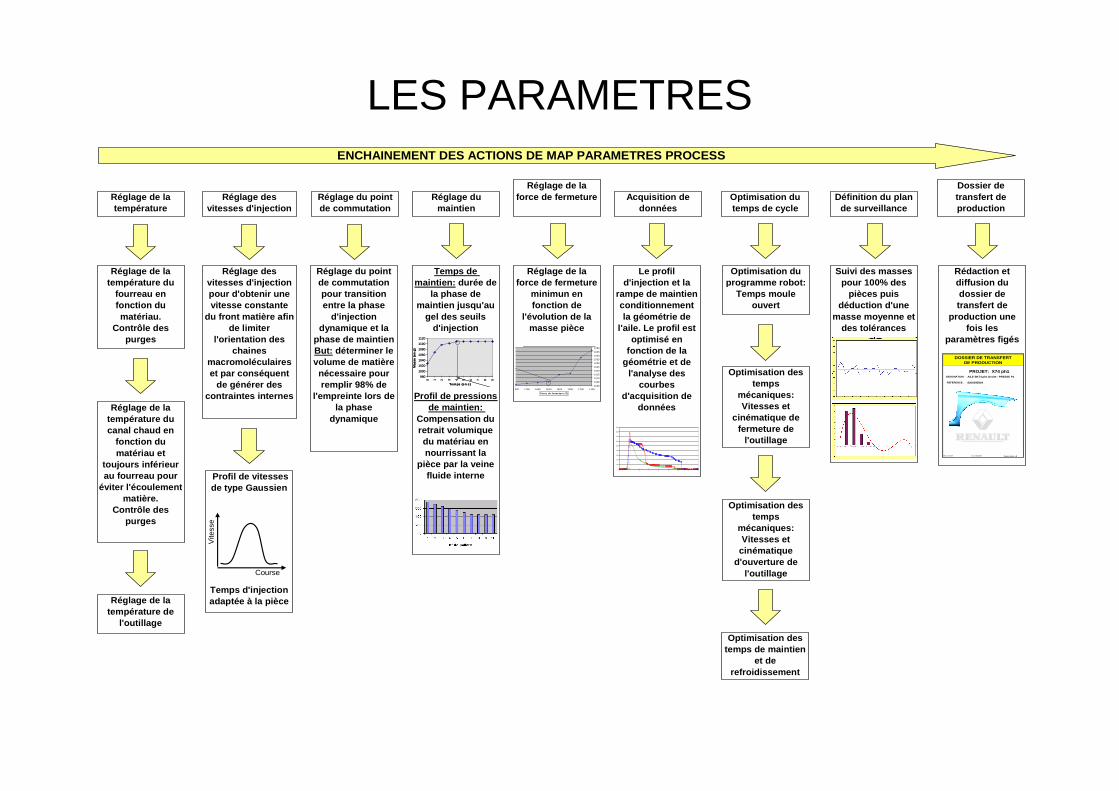
LES PARAMETRES
Réglage de la température
Réglage de la force de fermetureRéglage des
vitesses d'injectionRéglage du point de commutation
Réglage du maintien
Optimisation du temps de cycle
Définition du plan de surveillance
Dossier de transfert de production
ENCHAINEMENT DES ACTIONS DE MAP PARAMETRES PROCESS
Réglage de la température du
fourreau en fonction du matériau.
Contrôle des purges
Réglage de la température du canal chaud en
fonction du matériau et
toujours inférieur au fourreau pour
éviter l'écoulement matière.
Contrôle des purges
Réglage des vitesses d'injection pour d'obtenir une vitesse constante
du front matière afin de limiter
l'orientation des chaines
macromoléculaires et par conséquent
de générer des contraintes internes
Profil de vitesses de type Gaussien
Temps d'injection adaptée à la pièce
Course
Vite
sse
Réglage du point de commutation pour transition entre la phase
d'injection dynamique et la
phase de maintienBut: déterminer le volume de matière nécessaire pour remplir 98% de
l'empreinte lors de la phase
dynamique
Temps de maintien: durée de
la phase de maintien jusqu'au
gel des seuils d'injection
Profil de pressions de maintien:
Compensation du retrait volumique du matériau en nourrissant la
pièce par la veine fluide interne
980
1000
1020
1040
1060
1080
1100
1120
0 1 2 3 4 5 6 7 8 9
Temps (en s)
Mas
se (
en g
)
980
1000
1020
1040
1060
1080
1100
1120
0 1 2 3 4 5 6 7 8 9
Temps (en s)
Mas
se (
en g
)
Réglage de la force de fermeture
minimun en fonction de
l'évolution de la masse pièce
1000
1005
1010
1015
1020
1025
1030
1035
1040
1045
1050
11001200130014001500160017001800
Force de fe rmeture (T )
1000
1005
1010
1015
1020
1025
1030
1035
1040
1045
1050
11001200130014001500160017001800
Force de fe rmeture (T )
Acquisition de données
Le profil d'injection et la
rampe de maintien conditionnement la géométrie de
l'aile. Le profil est optimisé en
fonction de la géométrie et de
l'analyse des courbes
d'acquisition de données
0
100
200
300
400
500
600
700
800
900
0 5 10 15 20 25 30 35 40
pres
sion
en
bars
P. canal carotte MAX = 802 bars
Optimisation du programme robot:
Temps moule ouvert
Optimisation des temps
mécaniques: Vitesses et
cinématique de fermeture de
l'outillage
Optimisation des temps
mécaniques: Vitesses et
cinématique d'ouverture de
l'outillage
Optimisation des temps de maintien
et de refroidissement
Suivi des masses pour 100% des
pièces puis déduction d'une
masse moyenne et des tolérances
Rédaction et diffusion du dossier de transfert de
production une fois les
paramètres figés
PROJET: X74 ph1DESIGNATION: AILE BK74 ph1 Droite - PRESSE P1
REFERENCE:
DIMat - UET AET Date: Dossier indice: A
DOSSIER DE TRANSFERTDE PRODUCTION
20/01/2006
8200295804
Réglage de la température de
l'outillage
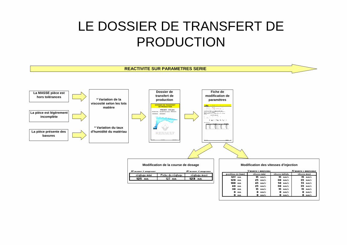
LE DOSSIER DE TRANSFERT DE PRODUCTION
REACTIVITE SUR PARAMETRES SERIE
La MASSE pièce est hors tolérances
Dossier de transfert de production
PROJET: X74 ph1DESIGNATION: AILE BK74 ph1 Droite - PRESSE P1
REFERENCE:
DIMat - UET AET Date: Dossier indice: A
DOSSIER DE TRANSFERTDE PRODUCTION
20/01/2006
8200295804
Fiche de modification de
paramètres
Modification de la course de dosage
La pièce est légèrement incomplète
La pièce présente des bavures
* Variation de la viscosité selon les lots
matière
* Variation du taux d'humidité du matériau
Modification des vitesses d'injection
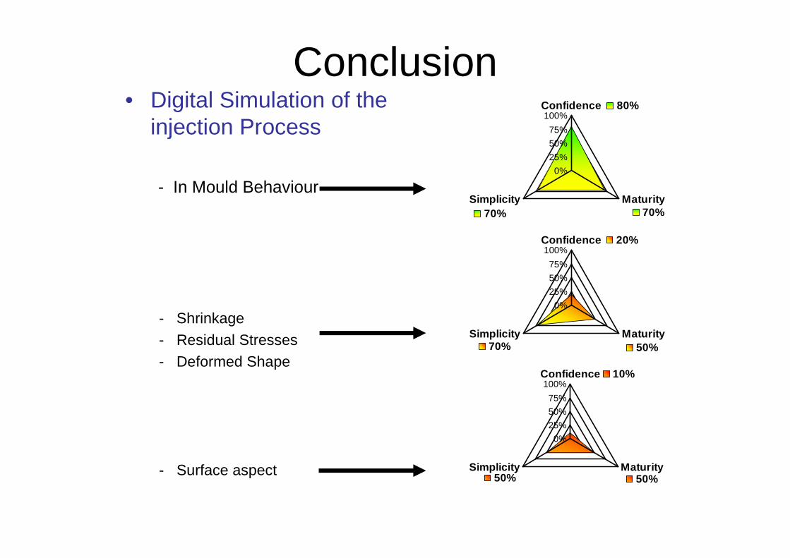
Conclusion • Digital Simulation of the
injection Process
- In Mould Behaviour
- Shrinkage
- Residual Stresses- Deformed Shape
- Surface aspect
80%
70%70%
0%
25%
50%
75%
100%Confidence
MaturitySimplicity
20%
50%70%
0%
25%
50%
75%
100%Confidence
MaturitySimplicity
10%
50%50%
0%
25%
50%
75%
100%Confidence
MaturitySimplicity
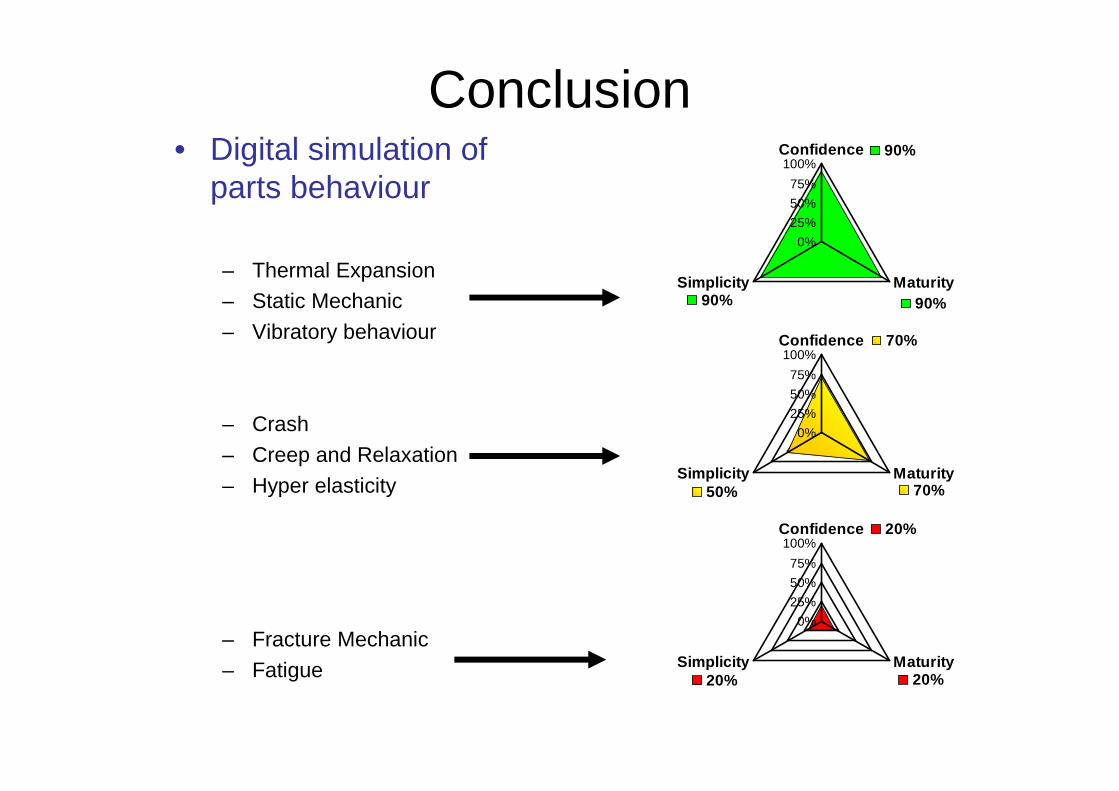
Conclusion• Digital simulation of
parts behaviour
– Thermal Expansion– Static Mechanic
– Vibratory behaviour
– Crash
– Creep and Relaxation
– Hyper elasticity
– Fracture Mechanic
– Fatigue
90%
90%90%
0%
25%
50%
75%
100%Confidence
MaturitySimplicity
70%
70%50%
0%
25%
50%
75%
100%Confidence
MaturitySimplicity
20%
20%20%
0%
25%
50%
75%
100%Confidence
MaturitySimplicity