CONVEYORS & FILTRATION - Machine Protection Solutions
28
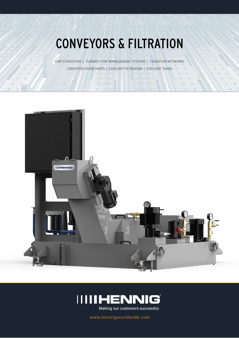
www.hennigworldwide.com Making our customers successful. CONVEYORS & FILTRATION CHIP CONVEYORS | TURNKEY CHIP MANAGEMENT SYSTEMS | CONVEYOR NETWORKS CONVEYOR SPARE PARTS | COOLANT FILTRATION | COOLANT TANKS
Transcript of CONVEYORS & FILTRATION - Machine Protection Solutions
www.hennigworldwide.com
Making our customers successful.
CONVEYORS & FILTRATIONCHIP CONVEYORS | TURNKEY CHIP MANAGEMENT SYSTEMS | CONVEYOR NETWORKS
CONVEYOR SPARE PARTS | COOLANT FILTRATION | COOLANT TANKS
Making our customers successful.
1
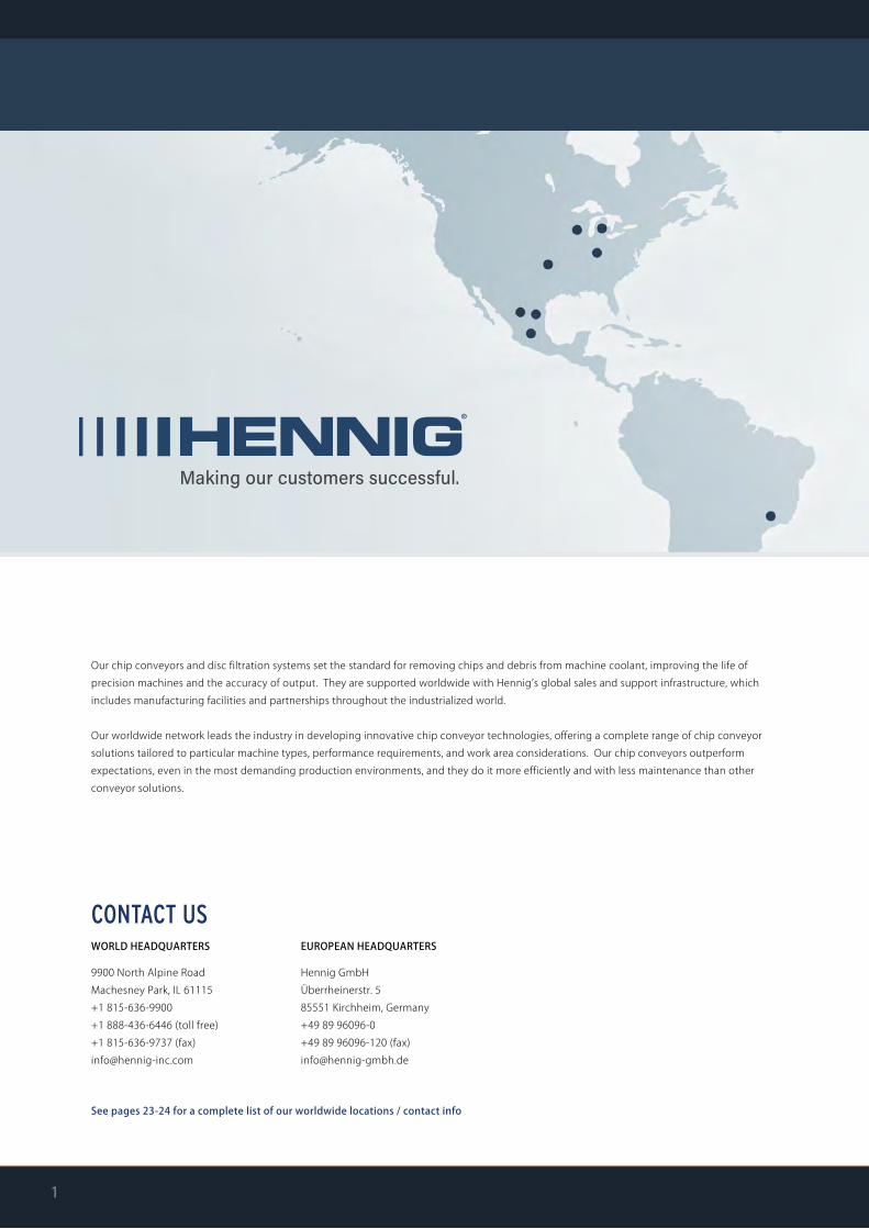
CONTACT USWORLD HEADQUARTERS
9900 North Alpine RoadMachesney Park, IL 61115+1 815-636-9900+1 888-436-6446 (toll free)+1 815-636-9737 (fax)[email protected]
EUROPEAN HEADQUARTERS
Hennig GmbHÜberrheinerstr. 585551 Kirchheim, Germany+49 89 96096-0+49 89 96096-120 (fax)[email protected]
See pages 23-24 for a complete list of our worldwide locations / contact info
Our chip conveyors and disc filtration systems set the standard for removing chips and debris from machine coolant, improving the life ofprecision machines and the accuracy of output. They are supported worldwide with Hennig’s global sales and support infrastructure, which includes manufacturing facilities and partnerships throughout the industrialized world.
Our worldwide network leads the industry in developing innovative chip conveyor technologies, offering a complete range of chip conveyor solutions tailored to particular machine types, performance requirements, and work area considerations. Our chip conveyors outperformexpectations, even in the most demanding production environments, and they do it more efficiently and with less maintenance than other conveyor solutions.
w w w . h e n n i g w o r l d w i d e . c o m 2
3-4
5-8
9
10
11-12
CONVEYOR OVERVIEW / SELECTION GUIDE
CONVEYOR TYPES
CUSTOM / TURNKEY SYSTEMS
CONVEYOR NETWORKS
SERVICE & SPARE PARTS
TABLE OF CONTENTS
13-14
15-16
17-18
19-22
23-24
CHIP DISC FILTRATION (CDF)
ADDITIONAL FILTRATION TYPES
COOLANT TANKS
REQUEST FOR QUOTE SHEETS
WORLDWIDE FACILITIES / CONTACT INFO
BELL
CHIP CONVEYORS & CHIP FORM SPECIFICATIONS
BELT-TYPE page 8
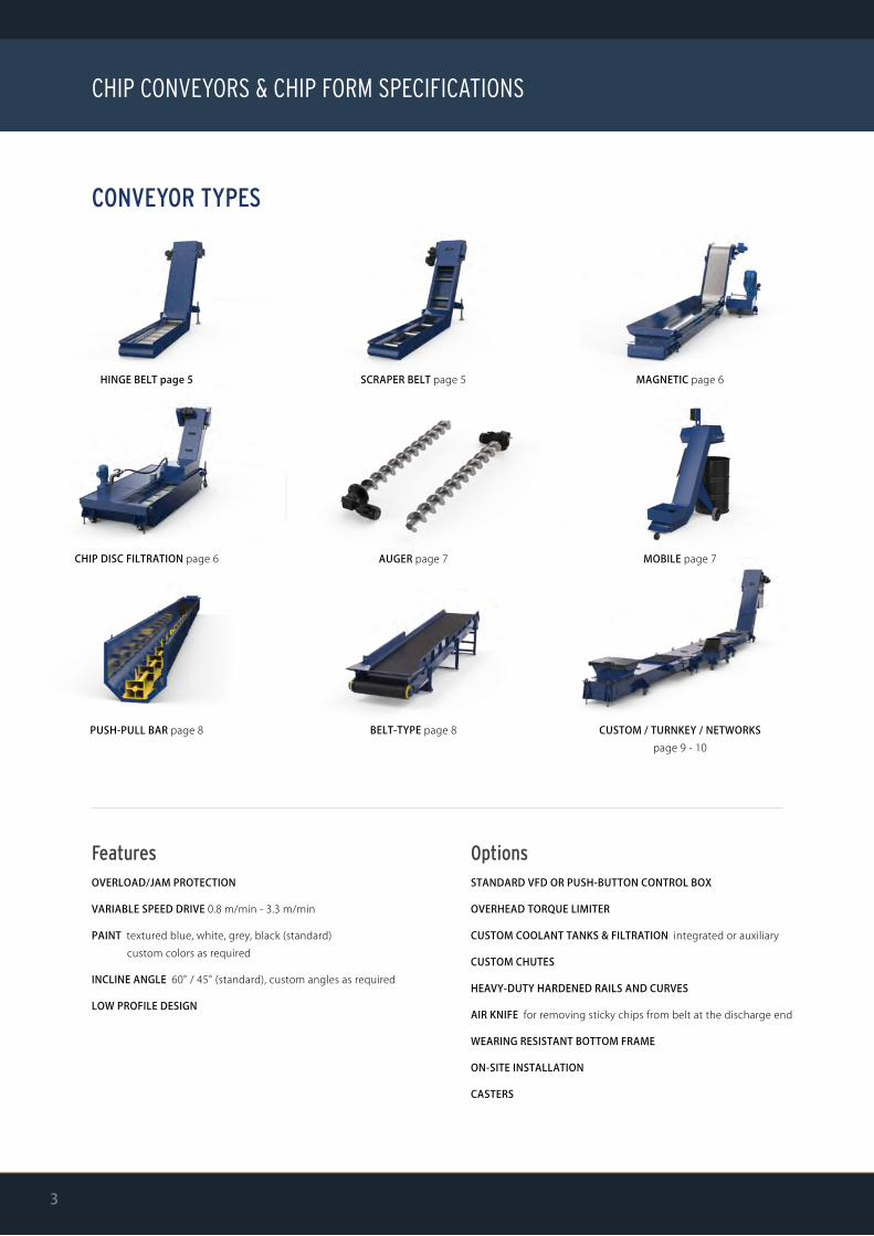
CONVEYOR TYPES
SCRAPER BELT page 5
AUGER page 7
PUSH-PULL BAR page 8
CHIP DISC FILTRATION page 6
CUSTOM / TURNKEY / NETWORKS page 9 - 10
HINGE BELT page 5 MAGNETIC page 6
MOBILE page 7
3
FeaturesOVERLOAD/JAM PROTECTION
VARIABLE SPEED DRIVE 0.8 m/min - 3.3 m/min
PAINT textured blue, white, grey, black (standard) custom colors as required
INCLINE ANGLE 60° / 45° (standard), custom angles as required
LOW PROFILE DESIGN
OptionsSTANDARD VFD OR PUSH-BUTTON CONTROL BOX
OVERHEAD TORQUE LIMITER
CUSTOM COOLANT TANKS & FILTRATION integrated or auxiliary
CUSTOM CHUTES
HEAVY-DUTY HARDENED RAILS AND CURVES
AIR KNIFE for removing sticky chips from belt at the discharge end
WEARING RESISTANT BOTTOM FRAME
ON-SITE INSTALLATION
CASTERS
BELL
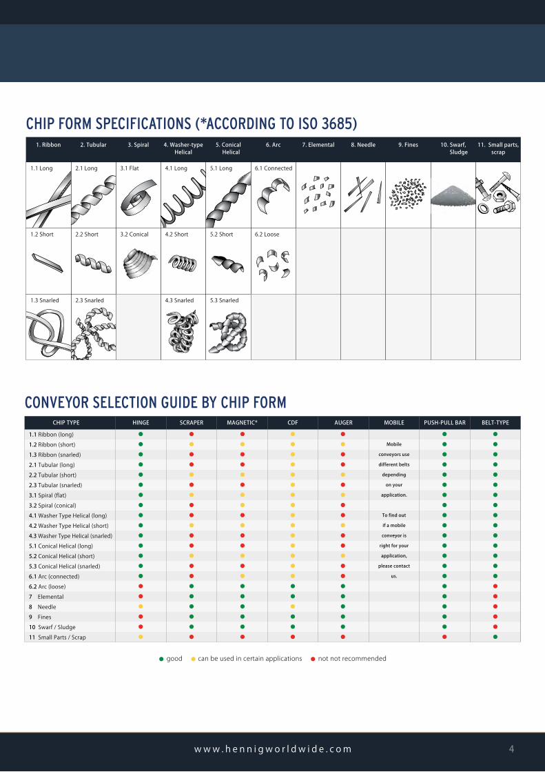
CHIP TYPE
1.1 Ribbon (long)1.2 Ribbon (short)1.3 Ribbon (snarled)2.1 Tubular (long)2.2 Tubular (short)2.3 Tubular (snarled)3.1 Spiral (flat)3.2 Spiral (conical)4.1 Washer Type Helical (long)4.2 Washer Type Helical (short)4.3 Washer Type Helical (snarled)5.1 Conical Helical (long)5.2 Conical Helical (short)5.3 Conical Helical (snarled)6.1 Arc (connected)6.2 Arc (loose)7 Elemental8 Needle9 Fines10 Swarf / Sludge11 Small Parts / Scrap
HINGE SCRAPER MAGNETIC* CDF AUGER MOBILE PUSH-PULL BAR BELT-TYPE
⃝
⃝
⃝
⃝
⃝
⃝
⃝
⃝
⃝
⃝
⃝
⃝
⃝
⃝
⃝
⃝
⃝
⃝
⃝
⃝
⃝
⃝
⃝
⃝
⃝
⃝
⃝
⃝
⃝
⃝
⃝
⃝
⃝
⃝
⃝
⃝
⃝
⃝
⃝
⃝
⃝
⃝
⃝
⃝
⃝
⃝
⃝
⃝
⃝
⃝
⃝
⃝
⃝
⃝
⃝
⃝
⃝
⃝
⃝
⃝
⃝
⃝
⃝
⃝
⃝
⃝
⃝
⃝
⃝
⃝
⃝
⃝
⃝
⃝
⃝
⃝
⃝
⃝
⃝
⃝
⃝
⃝
⃝
⃝
⃝
⃝
⃝
⃝
⃝
⃝
⃝
⃝
⃝
⃝
⃝
⃝
⃝
⃝
⃝
⃝
⃝
⃝
⃝
⃝
⃝
Mobile
conveyors use
different belts
depending
on your
application.
To find out
if a mobile
conveyor is
right for your
application,
please contact
us.
⃝
⃝
⃝
⃝
⃝
⃝
⃝
⃝
⃝
⃝
⃝
⃝
⃝
⃝
⃝
⃝
⃝
⃝
⃝
⃝
⃝
⃝
⃝
⃝
⃝
⃝
⃝
⃝
⃝
⃝
⃝
⃝
⃝
⃝
⃝
⃝
⃝
⃝
⃝
⃝
⃝
⃝
CONVEYOR SELECTION GUIDE BY CHIP FORM
1. Ribbon 2. Tubular 3. Spiral 4. Washer-type Helical
5. Conical Helical
6. Arc 7. Elemental 8. Needle 9. Fines 10. Swarf, Sludge
11. Small parts,scrap
1.1 Long 2.1 Long 3.1 Flat 4.1 Long 5.1 Long 6.1 Connected
1.2 Short 2.2 Short 3.2 Conical 4.2 Short 5.2 Short 6.2 Loose
1.3 Snarled 2.3 Snarled 4.3 Snarled 5.3 Snarled
CHIP FORM SPECIFICATIONS (*ACCORDING TO ISO 3685)
w w w . h e n n i g w o r l d w i d e . c o m 4
⃝ good ⃝ can be used in certain applications ⃝ not not recommended

HINGE (link, chain)A proven conveyor solution for a variety of materials, chip types, and chip loads. Hinge belts, the most common conveyor type, can be modified to handle more troublesome waste like tough scrap and heavy parts.
optionsBELT DESIGN plain, perforated, dimpled, combo
BELT PITCHES “ (MM) 1.5 (38.1), 2.5 (63.0), 4.0 (101.6), 6.0 (152.4)
CLEATS serrated, flat, inverted "v", custom
INTEGRATED COOLANT TANK
COOLANT FILTRATION
HEAVY-DUTY IMPACT PLATES for heavy scrap or parts
TOP HAT COVER for bundled chips
HINGE KIT service / replacement parts (see pages 11-12)
SCRAPER (drag, flight)An ideal solution for fine chips and swarf, the scraper belt moves in reverse, collecting and dragging chips up the incline to the discharge end. Standard scraper paddles can be customized with wipers to the application.
optionsPADDLES standard or custom angle
WIPERS
INTEGRATED COOLANT TANK
COOLANT FILTRATION
SOLID DRUM MAGNET for floating, ferrous chips when using coolant
WEARING RESISTANT CONSTRUCTION with hardened rails and curves / bottom frame
BELL
CONVEYOR TYPES
5

MAGNETICThe magnetic conveyor plays a very specific role in chip management - it’sintended for ferrous material applications which produce small chips and fines.
optionsCOOLANT TANKS
HIGH TEMPERATURE RESISTANCE
SOLID DRUM MAGNET to clean fine particles from the coolant
CHIP DISC FILTRATION (CDF)The patented Chip Disc Filtration (CDF) technology achieves high levelsof filtration without two separate belts. Our patented disc design providesa direct coolant flow path into the coolant reservoir and can filter a widevariety of materials, both in water and oil based coolant, down to 25microns nominal.
optionsSOLID ROTATING MAGNETIC DRUMfor collecting cast iron sludge/swarf
BELT TYPE hinge or scraper belt
FILTER DISC SIZE 10", 12", 16"
SINGLE OR MULTIPLE DISCSdepending on coolant flow rate
See page 13-14 for more information.
For additional filtration options, see page 15-16.
BELL
w w w . h e n n i g w o r l d w i d e . c o m 6

AUGER (screw)Ideal for limited space applications, the auger system can be installed in the machine tool or directly into the foundation / slab. The addition of a mobile (transfer) conveyor can be used to roll around the shop and assist with chip removal from high production auger fed systems.
optionsTORQUE LIMITER
INSTALLATION in auger or directly in machine frame
SCREW with or without shaft
MOBILE (TRANSFER) SETUP See below for details
MOBILE (auger-assisting, portable)The mobile conveyor provides machine operators with a convenientway to lift chips into full size barrel or hopper-high receptacles. Itreduces machine clean-out effort and eliminates back related fatigue. The portable conveyor can be used for periodic clean-out of multiple machines or dedicated full time to any machine generating high volumes of chips. Position the conveyor under the chip chute of any auger chip flume, plug it in and turn it on. Coolant that collects in the conveyor will be carried out by the chips so the conveyor never requires draining.
optionsADJUSTABLE CHIP CHUTEThe opening of the chip hopper may be oriented directly towardthe tail section of the conveyor, to the right, or to the left, byunscrewing the four bolts holding the hopper in place, removingit, rotating it to the desired position and bolting it back in place.
A. Toward tail section
Adjustable Chip Chute Orientation
B. With APCQ C. To Left D. To Right
BELL
CONVEYOR TYPES
7
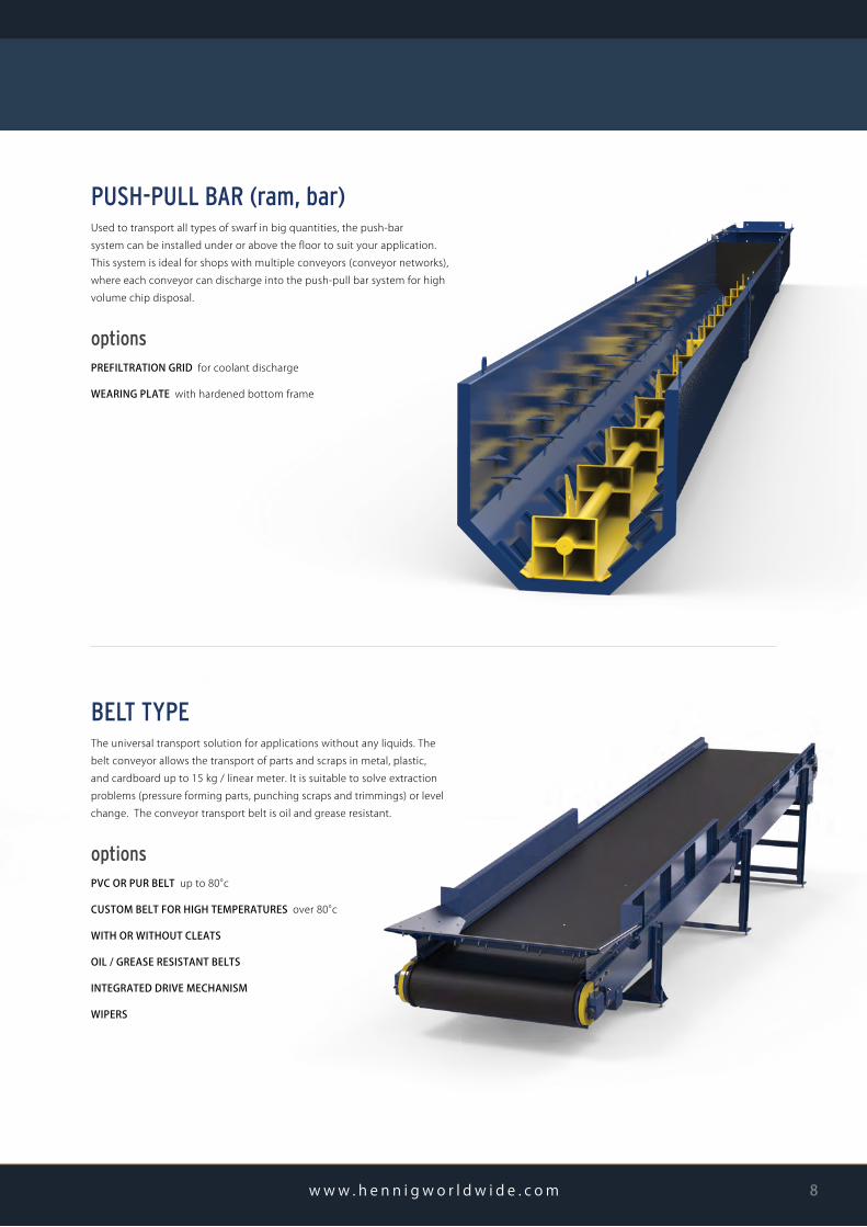
PUSH-PULL BAR (ram, bar)Used to transport all types of swarf in big quantities, the push-barsystem can be installed under or above the floor to suit your application.This system is ideal for shops with multiple conveyors (conveyor networks), where each conveyor can discharge into the push-pull bar system for high volume chip disposal.
optionsPREFILTRATION GRID for coolant discharge
WEARING PLATE with hardened bottom frame
BELT TYPEThe universal transport solution for applications without any liquids. Thebelt conveyor allows the transport of parts and scraps in metal, plastic, and cardboard up to 15 kg / linear meter. It is suitable to solve extraction problems (pressure forming parts, punching scraps and trimmings) or level change. The conveyor transport belt is oil and grease resistant.
optionsPVC OR PUR BELT up to 80°c
CUSTOM BELT FOR HIGH TEMPERATURES over 80°c
WITH OR WITHOUT CLEATS
OIL / GREASE RESISTANT BELTS
INTEGRATED DRIVE MECHANISM
WIPERS
BELL
w w w . h e n n i g w o r l d w i d e . c o m 8

CUSTOM & TURNKEY SYSTEMSUnique work environments. Specialized machine configurations. Varying chip volumes. These are just a few of the special requirements that indicate the need for a custom chip conveyor solution. Hennig engineers can create modified or special solutions to meet the needs of virtually any application; for example, dust and gas removal during dry machining (pictured below), or part and scrap removal (pictured right).
If your conveyor system requires integration in the machine controls or automation beyond our standard control system, we can build a tailor-made solution that does the job. If you're looking to further process your chips for shredding or recycling, we can integrateany of the technology required.
optionsSUCTION DEVICE for fumes, mist, and dust
CHIP SHREDDER
SWARF CENTRIFUGE
SWIVELING CHUTES manual or automated
WEARING PLATE with hardened bottom frame
CHIP COMPACTOR
VIBRATING TABLE
FILTRATION
BELL
CUSTOM CONVEYORS & NETWORKS
9

CONVEYOR NETWORKSFully automate the waste removal in your facility with integrated coolant tanks and conveyor networks. For high-volume manufac-turers, Hennig’s integrated systems can automate the removal of chips on one or all of the machine tools in the shop. This system allows the user to spend more time manufacturing and less time sweeping and moving chips.
RIGHTAn integrated conveyor network. Smaller conveyors from the machining centers discharge onto the main exit conveyor for efficient chip removal from multiple machines.
BOTTOM LEFTAdjustable chip chutes can be positioned at multiple discharge angles.
BOTTOM RIGHTConveyors move chips from multiple machining centers onto one integrated conveyor for easy and efficient chip removal.
BELL
w w w . h e n n i g w o r l d w i d e . c o m 10

When your conveyor needs service or repair, we have parts in stock to get your conveyor up and running, and also the skilled personnel to repair or replace the damaged or worn parts.
Conveyor belts, drive motors, and other parts can get damaged, worn, or just get old. Before investing in an entirely new system, check with us to see if your existing system can be repaired.
BELT REPLACEMENT / KITS
hinge belt
scraper belt
To order spare parts, simply provide us with the Hennig No., Serial No., and Customer No. found on your conveyor tag (typically found on either side of the discharge head), and the parts you need to replace from the list above.
Look for this tag on your conveyor system for the reference numbers
⓱⓲
⓳
㉗㉖
㉕
CONVEYOR PARTS BELTS / BELT KITS
25 Hinge Belt (whole belt replacement)
17 Hinge Kit (standard)
18 Hinge Kit (with plain cleat)
19 Hinge Kit (with serrated cleat)
26 Scraper Belt (whole belt replacement)
27 Scraper Blade Kit
12 Drive Chain
13 Flip Lid
14 Gear Motor Sprocket
15 Gear Motor
16 Adjustable Supports
20 Idler Shaft Assembly (if provided originally)
22 Control Box (VFD)
21 Motor Bracket
23 Motor Cover
24 Caster Assembly (option)
1 Front Chain Guard
2 Torque Limiter Assembly
3 Inside Chain Guard
4 Take-Up Bearing
5 Belt Sprocket
6 LH Inner Guard
7 RH Inner Guard
8 Torque Limiter Key / Direct Drive Key
9 Belt Sprocket Key
10 Drive Shaft
11 Bearing Cover
MADE IN GERMANY
REFERENCE NO.
ORDER NO.
DRAWING NO.
DATE
Hennig GmbH Überrheinerstr. 5, 85551 Kirchheim, Germany|+49 89 96096-0|www.hennigworldwide.com
BELL
CONVEYOR SERVICE & SPARE PARTS
11
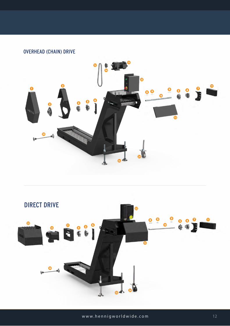
DIRECT DRIVE
㉑㉓⓯ ❹ ❺ ❻
㉒
❾❿
❽ ❾ ❼❹❺ ⓫
⓴
⓰ ㉔
⓭
OVERHEAD (CHAIN) DRIVE
❶ ❸
❹ ❺
❼❾
❿
⓬
⓭
⓮
⓯
⓰
⓴
❷
❹❺
❻
❽⓫
㉔
㉒
❾
BELL
w w w . h e n n i g w o r l d w i d e . c o m 12
optionsBELT TYPE can be used with scraper belt or hinge belt
FILTER DISC SIZE 10" (254mm), 12" (305mm), 16" (406 mm)
SINGLE OR MULTIPLE DISCS depending on coolant flow rate
SOLID ROTATING MAGNETIC DRUM for collecting cast iron sludge/swarf
CARTRIDGE OR CYCLONIC FILTERS for filtration down to 1 microns
AIR KNIFE for removing sticky chips from belt
SLUDGE POT for easy sludge/swarf disposal
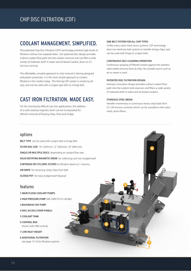
features1 MAIN FLOOD COOLANT PUMPS
2 HIGH PRESSURE PUMP 300-1000 PSI (21-69 Bar)
3 BACKWASH CDF PUMP
4 DISC ACCESS COVER PANELS
5 COOLANT TANK
6 CONTROL BOX shown with HMI controls
7 LOW INLET HEIGHT
8 ADDITIONAL FILTRATION see page 15-16 for filtration options
COOLANT MANAGEMENT. SIMPLIFIED.The patented Chip Disc Filtration (CDF) technology achieves high levels of filtration without two separate belts. Our patented disc design provides a direct coolant flow path into the coolant reservoir and can filter a wide variety of materials, both in water and oil based coolant, down to 25 microns nominal.
This affordable, versatile approach to chip removal is Hennig designed and patent protected. It is the most simple approach to coolantfiltration in the market today. The Hennig CDF system is simple by de-sign, and can be used with a scraper type belt or a hinge belt.
CAST IRON FILTRATION. MADE EASY.For the notoriously difficult cast iron applications, the additionof a solid rotating magnetic drum can be incorporated forefficient removal of floating chips, fines and sludge.
ONE BELT SYSTEM FOR ALL CHIP TYPESUnlike many nylon mesh drum systems, CDF technology does not need two belt systems to handle stringy chips, and can be used with hinge or scraper belts.
CONTINUOUS SELF-CLEANING OPERATIONContinuous spraying of filtered coolant against the stainless steel media removes fines & chips. No outside source such as air or steam is used.
PATENTED DISC FILTRATION DESIGNHennig's innovative design provides a direct coolant flow path into the coolant tank reservoir, and filters a wide variety of materials both in water and oil based coolants.
STAINLESS STEEL MEDIAHandles momentary or continuous heavy chip loads from 25-120 microns nominal, which can be a problem with nylon mesh, drum filters.
BELL
CHIP DISC FILTRATION (CDF)
13

HOW IT WORKS
❶ coarse chip removalWITH HINGE OR SCRAPER BELTThe belt (hinge or scraper) collects larger chips and particles for discharge into the chip hopper.
Removing coarse chips before they reach disc filter keeps them from bundling and jamming the system, which fosters extremely efficient fine particle filtration.
❷ fine particle filtrationFILTERING COOLANTSmall particles that escape the belt naturally migrate with the coolant flow to the rotating disc filter. There, particles down to 25 microns are collected and the cleaned coolant flows back into your tank.
REMOVING PARTICLESThe collected particles rotate with the disc filter and are lifted out of the coolant, towards the backwash spray. There, the particles are blasted onto the belt with a backwash spray and removed along with the coarse chips.
❸ cast iron micro-filtrationCOLLECTING & DISCARDING CAST IRON FINESIf you're looking to filter cast iron fines, the addition of a solid rotating magnetic drum allows for cast iron fines to be collected and removed from the coolant.
When enough particles have collected on the magnetic drum to form a heavy sludge, the sludge drops onto the dry conveyor incline and is discarded along with the coarse chips and particles that have been collected on the disc filter into the chip hopper.
magnetic drum forcol lect ing cast i ron f ines
BELL
w w w . h e n n i g w o r l d w i d e . c o m 14
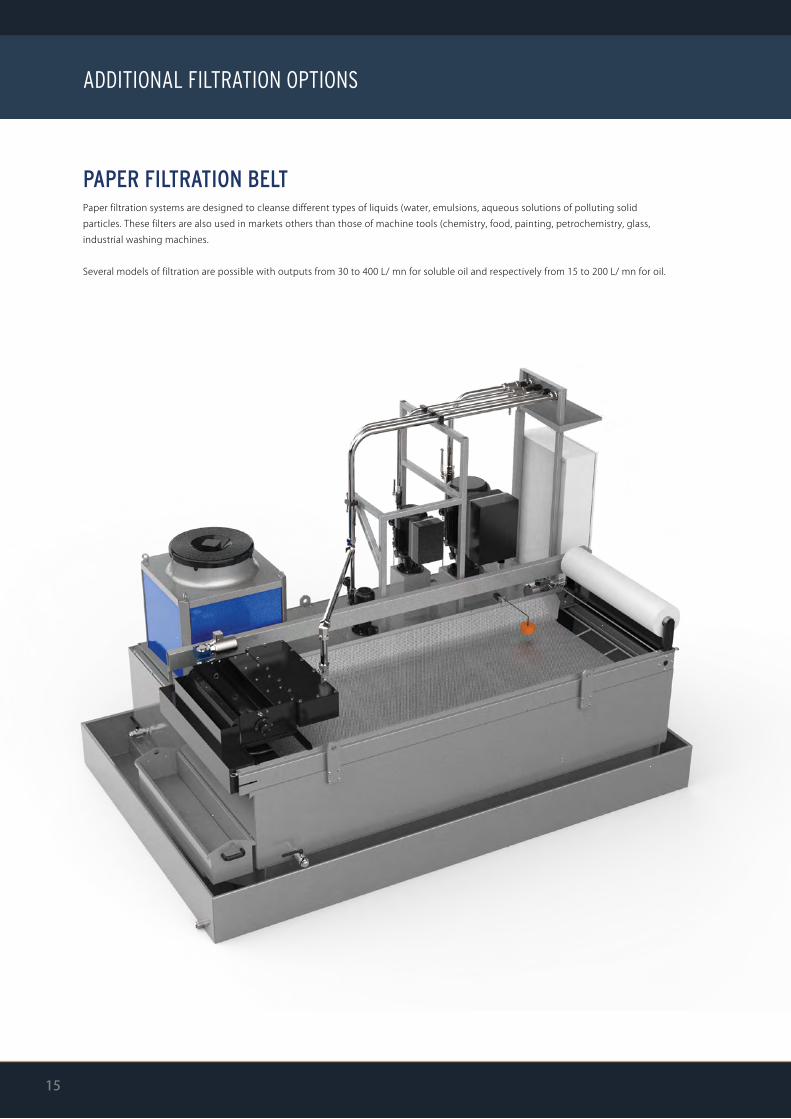
PAPER FILTRATION BELTPaper filtration systems are designed to cleanse different types of liquids (water, emulsions, aqueous solutions of polluting solidparticles. These filters are also used in markets others than those of machine tools (chemistry, food, painting, petrochemistry, glass, industrial washing machines.
Several models of filtration are possible with outputs from 30 to 400 L/ mn for soluble oil and respectively from 15 to 200 L/ mn for oil.
BELL
ADDITIONAL FILTRATION OPTIONS
15
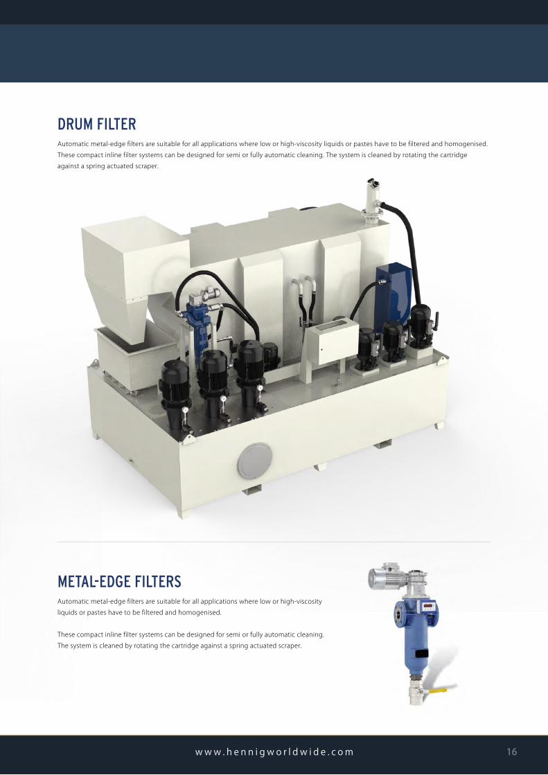
DRUM FILTERAutomatic metal-edge filters are suitable for all applications where low or high-viscosity liquids or pastes have to be filtered and homogenised.These compact inline filter systems can be designed for semi or fully automatic cleaning. The system is cleaned by rotating the cartridge against a spring actuated scraper.
BELL
w w w . h e n n i g w o r l d w i d e . c o m 16
METAL-EDGE FILTERSAutomatic metal-edge filters are suitable for all applications where low or high-viscosity liquids or pastes have to be filtered and homogenised.
These compact inline filter systems can be designed for semi or fully automatic cleaning. The system is cleaned by rotating the cartridge against a spring actuated scraper.

CUSTOM ENGINEERED.MADE TO ORDER.Using integrated or auxiliary tanks, coolant is quicklycleaned and recycled during the machining process,resulting in fewer interruptions and less downtime.
Our tanks are made from heavy gauge steel to provideleak-free service in harsh shop environments. Removable cover plates allow easy access to the tank’s interior for quick, easy maintenance. Liquid level sight gauges are a standard feature, and baffles, chip baskets, and removable screenscan also be added.
optionsBAFFLES / CHIP BASKETS / SCREENS
CARTRIDGE AND/OR CYCLONIC FILTERS
FLOAT SWITCHES
OIL SKIMMERS
COOLANT PUMPS
CUSTOM G / MIN (dm³/h) OR PSI REQUIREMENTS
INTEGRATED CONTROLS for pump / filter automation
CDF CONVEYOR WITH INTEGRATED COOLANT TANK
BELL
COOLANT TANKS
17
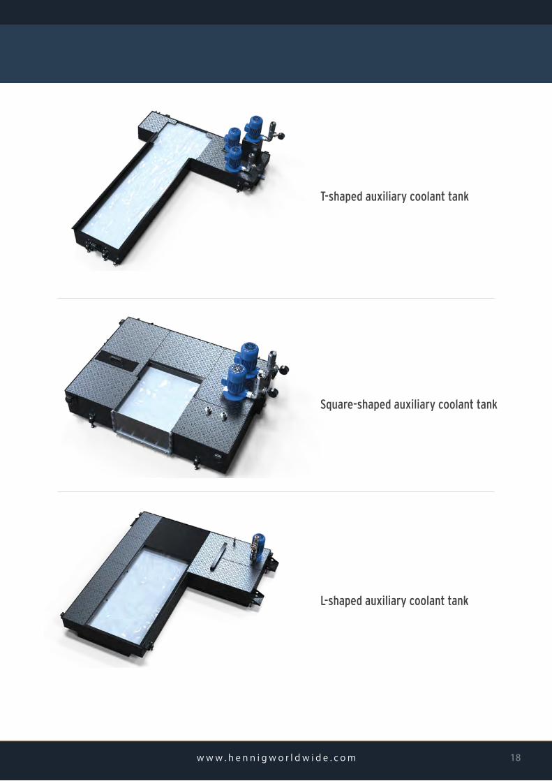
T-shaped auxiliary coolant tank
Square-shaped auxiliary coolant tank
L-shaped auxiliary coolant tank
BELL
w w w . h e n n i g w o r l d w i d e . c o m 18
Foot Location (choose one) ⃞ B ⃞ C _________ mm
Casters ⃞ Yes ⃞ No
Coolant Tank Required ⃞ Yes ⃞ No
Coolant Flow Rate _____________ L/min (total machine)
Coolant Slots ⃞ Left ⃞ Right ⃞ Both ⃞ None
Conveyor Speed (m/min) ⃞ 2.2 ⃞ 1.6 ⃞ Other ________________________
Overload Protection ⃞ Current Sensor ⃞ Mech. Torque Limiter ⃞ None
⃞ Other_________________________________________
Installed Location ⃞ On Floor ⃞ Inside Machine ⃞ Inside Pit ⃞ Inside Tank
Motor Location ⃞ Left ⃞ Right
Power Requirements V_______ Ph_______ Hz_______
Control Box ⃞ Yes ⃞ No
⃞ Variable Speed (standard) ⃞ 3 button box (fwd, rev, e-stop) ⃞ Auto/Manual Selector Switch
⃞ Electrical Plug (if yes, please specify) _____________________________________________
Control Box Location ⃞ Top Front ⃞ Top Left ⃞ Top Right
⃞ Left Side ⃞ Right Side ⃞ Stand Alone
Paint (texture powder coated) ⃞ RAL # _____________ ⃞ Other ________________________________
COMPANY (complete address)_________________________________________________________
_________________________________________________________
_________________________________________________________
_________________________________________________________
Name _____________________________________________________________
Title _____________________________________________________________
E-mail _____________________________________________________________
Phone ________________ Fax ________________ Date _____/_____/_________
Brand ⃞ Hennig ⃞ Enomoto ⃞ Sermeto ⃞ Cobsen ⃞ Other ______________________________________________________________________________
Part # _______________________________ Serial # _______________________________ Belt Type ⃞ Hinge (⃝ Plain ⃝ Perf ⃝ Dimple) ⃞ Scraper ⃞ Magnetic
EXISTING CONVEYOR (If you have the conveyor part number, disregard the sections below)
Make ________________________________________ Model ________________________________________ Available References ⃞ Photos ⃞ Drawings
Type ⃞ Lathe ⃞ Milling ⃞ Drilling ⃞ Tapping ⃞ Other _____________________________________________ Chip Volume ______________ dm³/h
Spindle Power ____________ kW Available Power ⃞ 400 ⃞ 220 ⃞ 110 ⃞ 24 VDC ⃞ Other _____________________________________
Chip Material ⃞ Soft Steel ⃞ Hard Steel ⃞ Stainless Steel ⃞ Brass/Copper ⃞ Cast Iron ⃞ Aluminum ⃞ Cast Aluminum ⃞ Other_____________________________
Kind of Chips ⃞ Fine ⃞ Broken ⃞ Large Broken ⃞ Lg Bushy ⃞ Tight Bushy
MACHINE INFORMATION
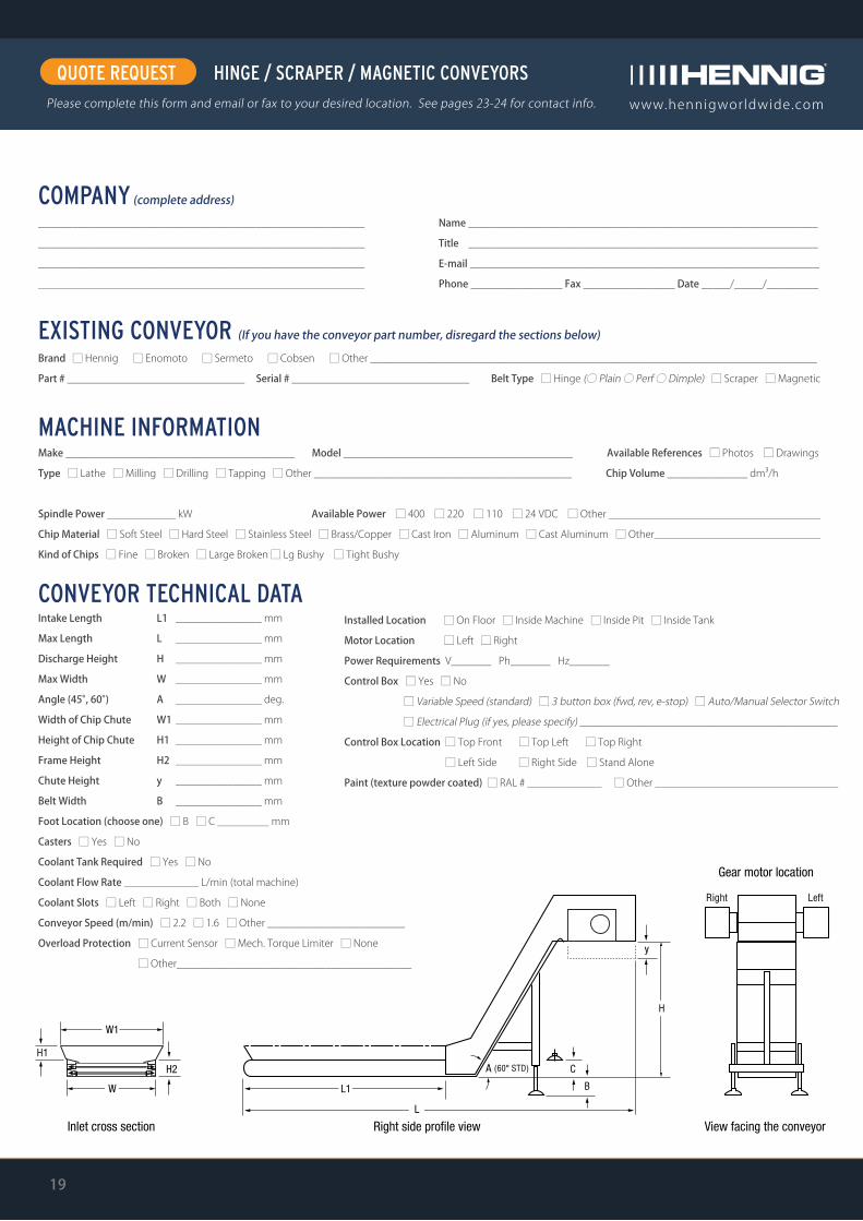
Intake Length
Max Length
Discharge Height
Max Width
Angle (45°, 60°)
Width of Chip Chute
Height of Chip Chute
Frame Height
Chute Height
Belt Width
L1
L
H
W
A
W1
H1
H2
y
B
_______________ mm
_______________ mm
_______________ mm
_______________ mm
_______________ deg.
_______________ mm
_______________ mm
_______________ mm
_______________ mm
_______________ mm
CONVEYOR TECHNICAL DATA
19
www.hennigworldwide.com
QUOTE REQUESTPlease complete this form and email or fax to your desired location. See pages 23-24 for contact info.
HINGE / SCRAPER / MAGNETIC CONVEYORS

Installed Location ⃞ On Floor ⃞ Inside Machine ⃞ Inside Pit ⃞ Inside Tank
Motor Location ⃞ Left ⃞ Right
Power Requirements V_______ Ph_______ Hz_______
Control Box ⃞ Yes ⃞ No
⃞ Variable Speed (standard) ⃞ 3 button box (fwd, rev, e-stop) ⃞ Auto/Manual Selector Switch
⃞ Electrical Plug (if yes, please specify) _____________________________________________
Control Box Location ⃞ Top Front ⃞ Top Left ⃞ Top Right
⃞ Left Side ⃞ Right Side ⃞ Stand Alone
Paint (texture powder coated) ⃞ RAL # _____________ ⃞ Other ________________________________
COMPANY (complete address)_________________________________________________________
_________________________________________________________
_________________________________________________________
_________________________________________________________
Name _____________________________________________________________
Title _____________________________________________________________
E-mail _____________________________________________________________
Phone ________________ Fax ________________ Date _____/_____/_________
Brand ⃞ Hennig ⃞ Enomoto ⃞ Sermeto ⃞ Cobsen ⃞ Other ______________________________________________________________________________
Part # _______________________________ Serial # _______________________________ Belt Type ⃞ Hinge (⃝ Plain ⃝ Perf ⃝ Dimple) ⃞ Scraper ⃞ Magnetic
EXISTING CONVEYOR (If you have the conveyor part number, disregard the sections below)
Make ________________________________________ Model ________________________________________ Available References ⃞ Photos ⃞ Drawings
Type ⃞ Lathe ⃞ Milling ⃞ Drilling ⃞ Tapping ⃞ Other _____________________________________________ Chip Volume ______________ dm³/h
Spindle Power ____________ kW Available Power ⃞ 400 ⃞ 220 ⃞ 110 ⃞ 24 VDC ⃞ Other ____________________________________
Chip Material ⃞ Soft Steel ⃞ Hard Steel ⃞ Stainless Steel ⃞ Brass/Copper ⃞ Cast Iron ⃞ Aluminum ⃞ Cast Aluminum ⃞ Other_____________________________
Kind of Chips ⃞ Fine ⃞ Broken ⃞ Large Broken ⃞ Lg Bushy ⃞ Tight Bushy
MACHINE INFORMATION
Intake Length
Max Length
Discharge Height
Max Width
Angle (45°, 60°)
Width of Chip Chute
Height of Chip Chute
Frame Height
Chute Height
Belt Width
L1
L
H
W
A
W1
H1
H2
y
B
_______________ mm
_______________ mm
_______________ mm
_______________ mm
_______________ deg.
_______________ mm
_______________ mm
_______________ mm
_______________ mm
_______________ mm
CONVEYOR TECHNICAL DATA
Foot Location (choose one) ⃞ B ⃞ C _________ mm
Casters ⃞ Yes ⃞ No
Coolant Flow Rate _____________ L/min (total machine)
Coolant Type ⃞ Water Soluble ⃞ Synthetic ⃞ Oil ______ cSt ⃞ Other _______________
Filtration Level ⃞ 25-30 micron ⃞ 35-40 micron ⃞ 40-45 micron ⃞ Other __________
Conveyor Speed (m/min) ⃞ 2.2 ⃞ 1.6 ⃞ Other ________________________
Overload Protection ⃞ Current Sensor ⃞ Mech. Torque Limiter ⃞ None
⃞ Other_________________________________________
20w w w . h e n n i g w o r l d w i d e . c o m
www.hennigworldwide.com www.hennigworldwide.com
QUOTE REQUESTPlease complete this form and email or fax to your desired location. See pages 23-24 for contact info.
CHIP DISC FILTRATION

www.hennigworldwide.com
QUOTE REQUESTPlease complete this form and email or fax to your desired location. See pages 23-24 for contact info.
AUGER CONVEYORS
COMPANY (complete address)_________________________________________________________
_________________________________________________________
_________________________________________________________
_________________________________________________________
Name _____________________________________________________________
Title _____________________________________________________________
E-mail _____________________________________________________________
Phone ________________ Fax ________________ Date _____/_____/_________
End-to-End Length
Spiral Outside Diameter
Pitch
Spiral Metal Thickness
Drive Shaft Diameter
AUGER MEASUREMENTS
Make ________________________________________ Model ________________________________________ Available References ⃞ Photos ⃞ Drawings
Type ⃞ Lathe ⃞ Milling ⃞ Drilling ⃞ Tapping ⃞ Other _____________________________________________ Chip Volume ______________ dm³/h
MACHINE INFORMATION
1
2
3
4
5
____________ mm
____________ mm
____________ mm
____________ mm
____________ mm
Additional Information ________________________________________________________________
____________________________________________________________________________________
____________________________________________________________________________________
____________________________________________________________________________________
____________________________________________________________________________________
2
3
1
4
5
21
⃞ A (Internal hub bored to driveshaft, secured with bolt or set screw)
⃞ B (Slip connection that fits tightly onto driveshaft, connected with a pin)
⃞ C (Combination of A and B)
⃞ D (Spiral only, to be welded directly onto driveshaft)
MOUNTING TYPE
www.hennigworldwide.com
QUOTE REQUESTPlease complete this form and email or fax to your desired location. See pages 23-24 for contact info.
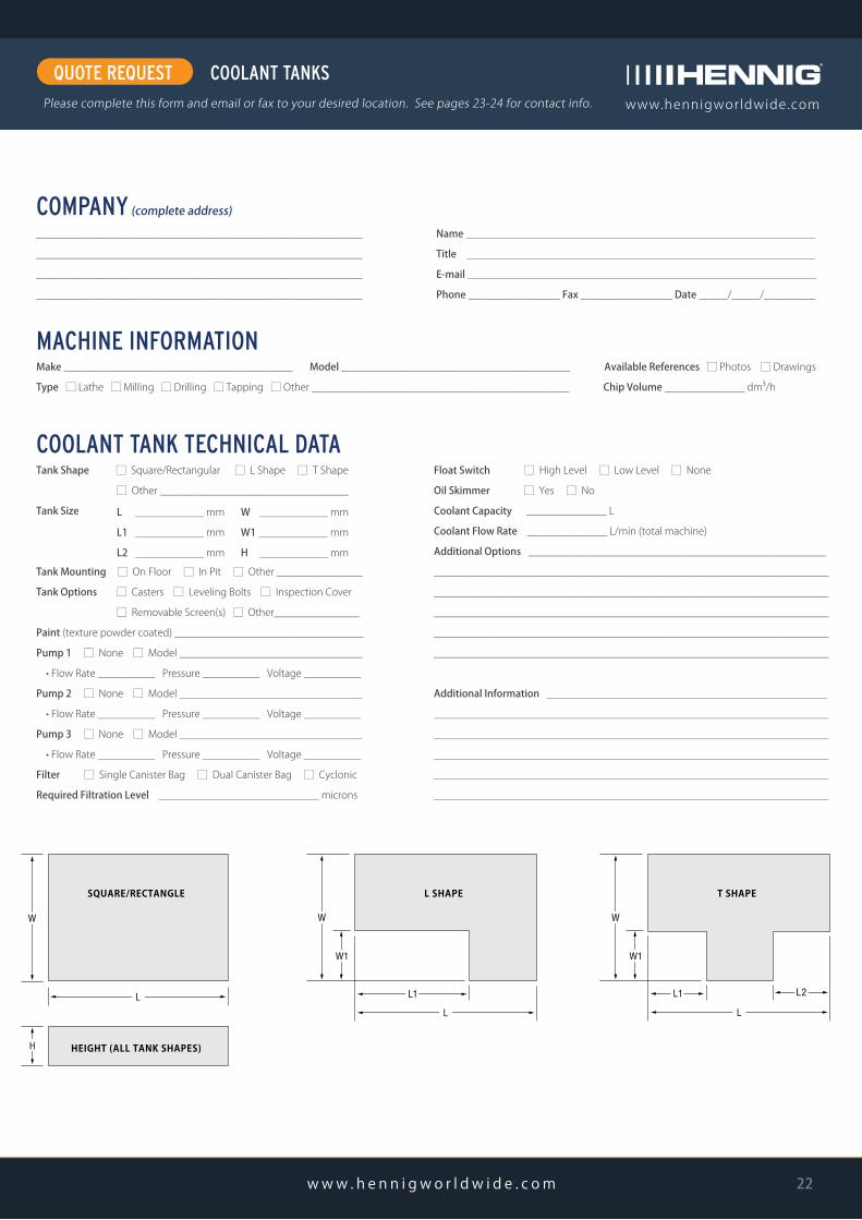
COOLANT TANKS
COMPANY (complete address)_________________________________________________________
_________________________________________________________
_________________________________________________________
_________________________________________________________
Name _____________________________________________________________
Title _____________________________________________________________
E-mail _____________________________________________________________
Phone ________________ Fax ________________ Date _____/_____/_________
Make ________________________________________ Model ________________________________________ Available References ⃞ Photos ⃞ Drawings
Type ⃞ Lathe ⃞ Milling ⃞ Drilling ⃞ Tapping ⃞ Other _____________________________________________ Chip Volume ______________ dm³/h
MACHINE INFORMATION
COOLANT TANK TECHNICAL DATATank Shape ⃞ Square/Rectangular ⃞ L Shape ⃞ T Shape
⃞ Other _________________________________
Tank Size
Tank Mounting ⃞ On Floor ⃞ In Pit ⃞ Other _______________
Tank Options ⃞ Casters ⃞ Leveling Bolts ⃞ Inspection Cover
⃞ Removable Screen(s) ⃞ Other_______________
Paint (texture powder coated) _________________________________
Pump 1 ⃞ None ⃞ Model ________________________________
• Flow Rate __________ Pressure __________ Voltage __________
Pump 2 ⃞ None ⃞ Model ________________________________
• Flow Rate __________ Pressure __________ Voltage __________
Pump 3 ⃞ None ⃞ Model ________________________________
• Flow Rate __________ Pressure __________ Voltage __________
Filter ⃞ Single Canister Bag ⃞ Dual Canister Bag ⃞ Cyclonic
Required Filtration Level ____________________________ microns
L
L1
L2
____________ mm
____________ mm
____________ mm
Float Switch ⃞ High Level ⃞ Low Level ⃞ None
Oil Skimmer ⃞ Yes ⃞ No
Coolant Capacity ______________ L
Coolant Flow Rate ______________ L/min (total machine)
Additional Options ____________________________________________________
_____________________________________________________________________
_____________________________________________________________________
_____________________________________________________________________
_____________________________________________________________________
_____________________________________________________________________
Additional Information _________________________________________________
_____________________________________________________________________
_____________________________________________________________________
_____________________________________________________________________
_____________________________________________________________________
_____________________________________________________________________
W
W1
H
____________ mm
____________ mm
____________ mm
22w w w . h e n n i g w o r l d w i d e . c o m

❺ Hennig, Inc. N. Carolina Service Center 8916 Pioneer Avenue, Suite C, Dock 14 Charlotte NC 28273 P: + 01 704-588-7200 F: + 01 704-588-7200 [email protected]
❻ Hennig / Gaden, S.A. de C.V. Calzada Abastos Nº 235 Col. Santa María Torreón Coahuila, C.P. 27020 P: + 01 (871) 268 2449 F: + 01 (871) 268 2449 [email protected]
❼ Hennig / Gaden, S.A. de C.V. Calle Primera Nº 1037 Col. Ministro Nazario Ortiz Saltillo, Coahuila, C.P. 25100 P: + 01 (844) 180 0294 F: + 01 (844) 180 029 [email protected]
❶ Hennig, Inc. Global Headquarters 9900 North Alpine Road Machesney Park, IL 61115 P: + 01 815-636-9900 F: + 01 815-636-1988 [email protected]
❷ Hennig, Inc. Oklahoma Service Center 900395 S. 3420 Road Chandler, OK 74834 P: + 01 405-258-6702 F: + 01 405-258-9971 [email protected]
❸ Hennig, Inc. Michigan Service Center 11879 Brookfield Road Livonia, MI 48150 P: + 01 734-523-8274 F: + 01 855-427-1549 [email protected]
❹ Hennig, Inc. Ohio Service Center 11431 Williamson Road Blue Ash, OH 45241 P: + 01 513-247-0838 F: + 01 513-247-0840 [email protected]
❽ Hennig / Gaden, S.A. de C.V. Silca Nº 4, Col. Vista Hermosa Tlalnepantla, Mexico, C.P. 54080 P: + 52 (55) 5318 4146 F: + 52 (55) 5319 32 [email protected]
❾ Cobsen Ltda. R. Benedito Mazulquim, 425 18550-000 Boituva CEP, Brazil P: + 55 15 3263-4042 F: + 55 15 3263-4070 [email protected]
23
BELL
HENNIG WORLDWIDE FACILITIES / CONTACTS
Making our customers successful.
Vertriebspartner
Servicestation
Stammsitz / Produktion / Vertrieb / Servicestation
Produktion / Vertrieb / Servicestation
Produktion / Vertrieb
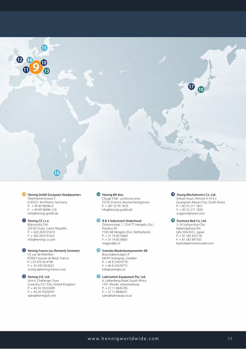
❿ Hennig GmbH European Headquarters Überrheinerstrasse 5 D-85551 Kirchheim, Germany P: + 49 89 96096-0 F: + 49 89 96096-120 [email protected]
⓫ Hennig CZ s.r.o. Klánovická 334 250 82 Úvaly, Czech Republic P: + 420 2810 91610 F: + 420 2810 91625 [email protected]
⓬ Hennig France sas (formerly Sermeto) 19, rue de Rebrillon 03300 Creuzier-le-Neuf, France P: +33 470 58 4740 F: + 33 470 58 0022 [email protected]
⓭ Hennig U.K. Ltd. Unit 6, Challenge Close Coventry CV1 5JG, United Kingdom P: + 44 24 76555690 F: + 44 24 76256591 [email protected]
⓮ Hennig BH doo. Ciljuge II bb - poslovna zona 75270 Zivinice, Bosnia Herzegovina P: + 387 35 95 1876 [email protected]
⓯ B & S Industrieel Onderhoud Zirkoonstraat 7, 7554 TT Hengelo (Ov.) Postbus 69 7550 AB Hengelo (Ov.), Netherlands P: + 31 74 8510600 F: + 31 74 8510605 [email protected]
⓰ Svenska Maskinkomponenter AB Brunnsäkersvägen 9 64593 Strängnäs, Sweden P: + 46 8 53470770 F: + 46 8 53470775 [email protected]
⓱ Lubrication Equipment Pty. Ltd. 6, Liebenberg Road, South Africa 1451 Alrode, Johannesburg P: + 27 11 8645785 F: + 27 11 8648231 [email protected]
⓲ Osung Mechatronics Co. Ltd. Jinbuk-myun Shincon-li 413-2 Gyungnam Masan-City, South Korea P: + 82 55 271 1821 F: + 82 55 271 1820 [email protected]
⓳ Enomoto BeA Co. Ltd. 5-10 Sohara Koa-Cho Kakamigahara-Shi, Gifu 504-8551, Japan P: + 81 583 832178 F: + 81 583 897435 [email protected]
w w w . h e n n i g w o r l d w i d e . c o m 24
BELL

BELL
NOTES
25

BELL
w w w . h e n n i g w o r l d w i d e . c o m 26
Making our customers successful.
www.hennigworldwide.com
DIN ISO 9001:2015 Data Subject To Change CF EE 1120 Copyright 2020
MAKING OUR CUSTOMERS SUCCESSFULFor over 65 years, Hennig Worldwide has been defining Excellence in Machine Protection, creating regional jobs,
serving their local communities, and supporting the global needs of machine tool customers.
Specializing in chip management, machine protection, facility safety, and generator enclosures,Hennig products optimize production and keep your facility clean and safe.
MACHINEPROTECTIONTelescopic Steel Covers
Machine Roof Bellow Covers
Modular Face Shields (XYZ Shields)
Flex Doors
Bellows
Aprons & Roll Up Covers
Walk-On Covers
Wiper Systems
Telescopic Springs
Cable Conduits
CHIPSOLUTIONSChip Conveyors
Turnkey Chip Management
Conveyor Networks
Conveyor Spare Parts
Coolant Filtration
Coolant Tanks
ENCLOSURES &FACILITY SAFETYGENSET Enclosures
Machine Enclosures
Platforms and Stairs
Guarding and Fencing
3D Printer Enclosures
Additive Manufacturing Enclosures
Scissor Lift Bellows
Special Fabrications