Composites piézoélectriques et diélectriques à base de...
31
1 Composites piézoélectriques et diélectriques à base de polymères fluorés Sara DALLE VACCHE Laboratoire de Technologie des Composites et Polymères (LTC) Ecole Polytechnique Fédérale de Lausanne (EPFL) CH-1015 Lausanne, Switzerland PLASTICS UPDATE, 12 novembre 2015
Transcript of Composites piézoélectriques et diélectriques à base de...

1
Composites piézoélectriques et diélectriques à base de polymères fluorés
Sara DALLE VACCHE Laboratoire de Technologie des Composites et Polymères (LTC)
Ecole Polytechnique Fédérale de Lausanne (EPFL) CH-1015 Lausanne, Switzerland
PLASTICS UPDATE, 12 novembre 2015
2
LTC
Created: 1990
Director: Prof. J.-A. Månson
Direction: P.-E. Bourban, Y. Leterrier, V. Michaud, C. Plummer
Staff: 20 members (postdocs, PhDs, engineers)
3
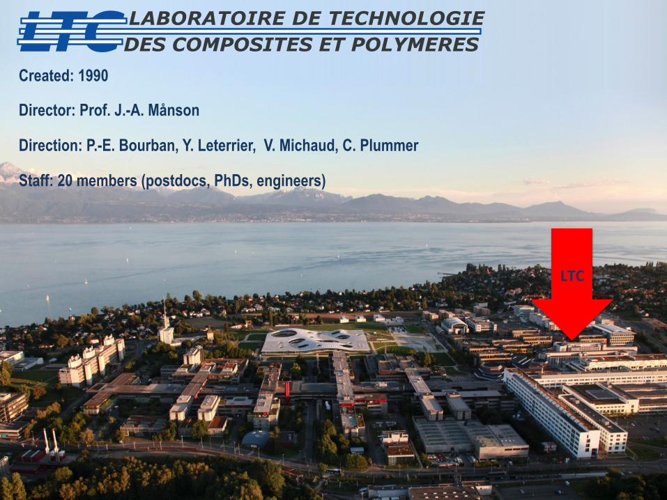
LTC creates the scientific base for the next generation of materials and processes in the fast-growing fields of polymers and composites: • incorporating unique additional functionality • developing new routes to cost-effective materials and manufacturing • scaling up to an industrial context (aerospace, automotive, building, medical,
electronics, sports…)
Research domains • Advanced Thermoset Composite Processing • Thermoplastic Composite Manufacturing • Smart Composites • Nanostructured materials • Biocomposites • Multilayer films • Cost and implementation strategies Main industrial sponsors • DaimlerChrysler, Ford, VW, Renault, USCAR • Johnson Controls, Vetrotex, ABB, Bekaert, KB • DuPont, Dow, EMS Chemie, Firmenich, Konarka, Solvay • Essilor, Tetra Pak, Alinghi, Solar Impulse, Swatch Group
4
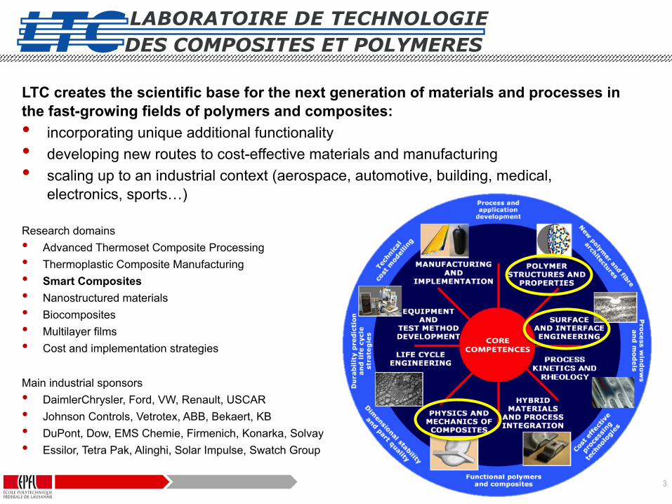
Outline
• Why dielectric and piezoelectric polymer composites • Process – structure – property analyses • Solvent based and melt processing
• Morphology and crystallinity
• Thermomechanical properties
• Barrier properties
• Dielectric and piezoelectric properties
• Application case • Self-sensing high pressure H2 storage vessel
• Conclusions and outlook
5
Why dielectric and piezoelectric composites
6
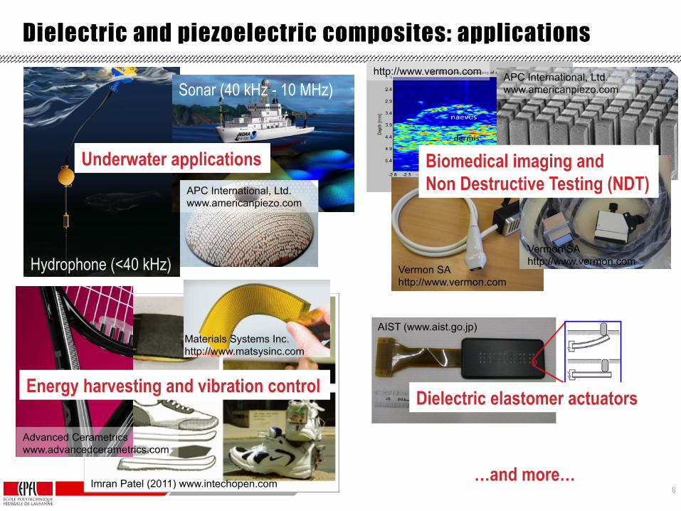
Dielectric and piezoelectric composites: applications
Hydrophone (<40 kHz)
Sonar (40 kHz - 10 MHz)
Underwater applications
Imran Patel (2011) www.intechopen.com
Materials Systems Inc. http://www.matsysinc.com
Dielectric elastomer actuators
AIST (www.aist.go.jp)
Energy harvesting and vibration control
Advanced Cerametrics www.advancedcerametrics.com
APC International, Ltd. www.americanpiezo.com
APC International, Ltd. www.americanpiezo.com
…and more…
http://www.vermon.com
Biomedical imaging and Non Destructive Testing (NDT)
Vermon SA http://www.vermon.com
Vermon SA http://www.vermon.com
7
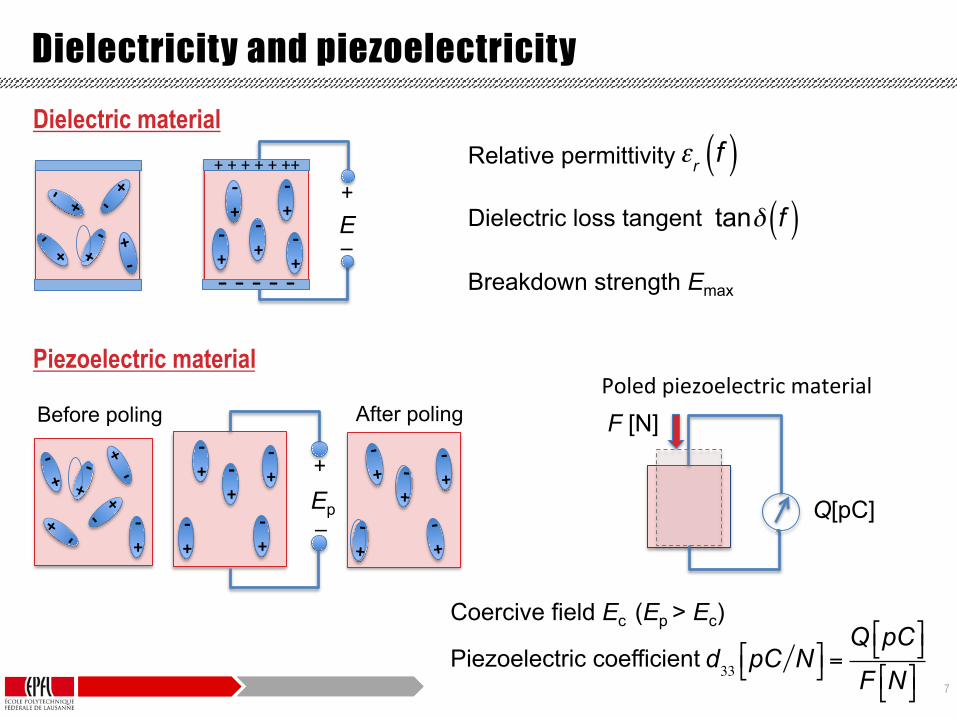
Relative permittivity Dielectric loss tangent Breakdown strength Emax
Dielectricity and piezoelectricity
Ep
After poling Before poling
+
_
F [N]
Q[pC]
d33 pC N!" #$=Q pC!" #$F N!" #$
εr f( )tanδ f( )
+ -‐
+ -‐
+ -‐
+ -‐ +
-‐
+ -‐
+ -‐
+ -‐
+ -‐ +
-‐
+ -‐
+ -‐
E +
_
+ + + + + ++
-‐ -‐ -‐ -‐ -‐
+ -‐
+ -‐
+ -‐
+ -‐
+ -‐
Dielectric material
Piezoelectric material
Coercive field Ec (Ep > Ec)
Piezoelectric coefficient
Poled piezoelectric material

8
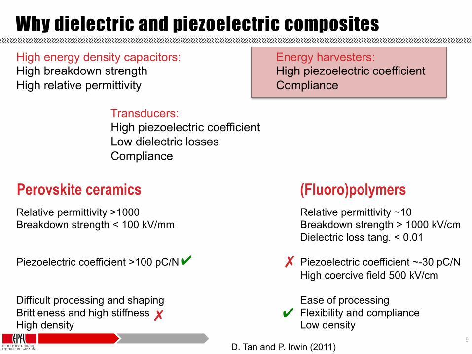
(Fluoro)polymers Perovskite ceramics Relative permittivity ~10 Breakdown strength > 1000 kV/cm Dielectric loss tang. < 0.01 Piezoelectric coefficient ~-30 pC/N High coercive field 500 kV/cm Ease of processing Flexibility and compliance Low density
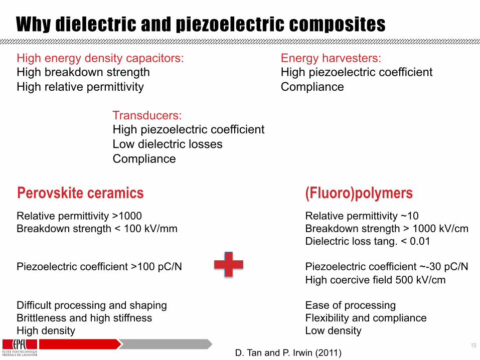
Why dielectric and piezoelectric composites
Relative permittivity >1000 Breakdown strength < 100 kV/mm Piezoelectric coefficient >100 pC/N Difficult processing and shaping Brittleness and high stiffness High density
High energy density capacitors: Energy harvesters: High breakdown strength High piezoelectric coefficient High relative permittivity Compliance
Transducers: High piezoelectric coefficient Low dielectric losses Compliance
✗ ✔
✔ ✗
D. Tan and P. Irwin (2011)
9
(Fluoro)polymers Perovskite ceramics Relative permittivity ~10 Breakdown strength > 1000 kV/cm Dielectric loss tang. < 0.01 Piezoelectric coefficient ~-30 pC/N High coercive field 500 kV/cm Ease of processing Flexibility and compliance Low density
Why dielectric and piezoelectric composites
Relative permittivity >1000 Breakdown strength < 100 kV/mm Piezoelectric coefficient >100 pC/N Difficult processing and shaping Brittleness and high stiffness High density
High energy density capacitors: Energy harvesters: High breakdown strength High piezoelectric coefficient High relative permittivity Compliance
Transducers: High piezoelectric coefficient Low dielectric losses Compliance
✗
✗
✔
✔
D. Tan and P. Irwin (2011)
10
(Fluoro)polymers Perovskite ceramics Relative permittivity ~10 Breakdown strength > 1000 kV/cm Dielectric loss tang. < 0.01 Piezoelectric coefficient ~-30 pC/N High coercive field 500 kV/cm Ease of processing Flexibility and compliance Low density
Why dielectric and piezoelectric composites
Relative permittivity >1000 Breakdown strength < 100 kV/mm Piezoelectric coefficient >100 pC/N Difficult processing and shaping Brittleness and high stiffness High density
High energy density capacitors: Energy harvesters: High breakdown strength High piezoelectric coefficient High relative permittivity Compliance
Transducers: High piezoelectric coefficient Low dielectric losses Compliance
D. Tan and P. Irwin (2011)

11
Types of composites
Commercial applications are mainly based on 2-2 and 1-3 composites Ø Fabrication and shaping may be
complex (e.g. dice & fill) 0-3 composites allow a cost effective polymer-like processing and shaping
R.E. Newnham (1978)
12
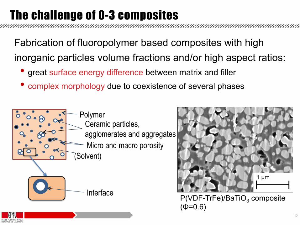
Fabrication of fluoropolymer based composites with high inorganic particles volume fractions and/or high aspect ratios: • great surface energy difference between matrix and filler • complex morphology due to coexistence of several phases
Polymer Ceramic particles, agglomerates and aggregates
(Solvent) Micro and macro porosity
The challenge of 0-3 composites
P(VDF-TrFe)/BaTiO3 composite (Φ=0.6)
Interface

13
Fluoropolymer composites : process – structure – property analyses

14
PVDF based polymers
Relative permittivity εr = 10 d33 = – 30 pC/N Ec = 500 kV/cm TC = 126 °C
H
C#
H
F#
C#
F#
F#
C#
F#
H
C#
F#n" m"
P(VDF-TrFE)
H
C#
H
F#
C#
F#
F#
C#
F#
H
C#
F#n" m"
PVDF H
α β
F
C
T > TC β è α
Paraelectric Piezoelectric
15
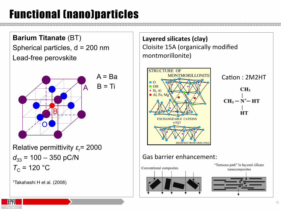
Layered silicates (clay) Cloisite 15A (organically modified montmorillonite) Gas barrier enhancement:
Functional (nano)particles
Barium Titanate (BT) Spherical particles, d = 200 nm Lead-free perovskite
A = Ba B = Ti
Relative permittivity εr= 2000 d33 = 100 – 350 pC/N TC = 120 °C 1Takahashi H et al. (2008)
a high-performance carbonaceous-silicate char, whichbuilds up on the surface during burning. This insulatesthe underlying material and slows the mass loss rate ofdecomposition products.
In a recent study, Zhu et al. [98] reported the fireretardant properties of PS/MMT nanocomposites,which were prepared using three different types ofnew organically modified MMT (see Fig. 25). Theyinitially used phosphonium salt for the modification ofclay, and then examined the differences betweenorgano ammonium and phosphonium salt treatmentsof clay fillers in nanocomposites towards thermalstability. The peak HRR for PS and the threenanocomposites is also shown graphically in Fig. 96.As mentioned above, the suggested mechanism bywhich clay nanocomposites function involves theformation of a char that serves as a barrier to bothmass and energy transport [17]. As the fraction of clayincreases, the amount of char that can be formedincreases, and the rate at which heat is releaseddecreases. One of these nanocomposites, OH-16, ismostly intercalated. This yields a slight reduction inthe rate of heat release compared with the other twosystems, which contain a significant exfoliatedfraction. This observation again supports the sugges-tion that an intercalated material is more effective thanan exfoliated material in fire retardance [433].
In contrast, the decrease in the rate of heat releasecorresponds to (1) a decrease in mass loss rate and theamount of energy released by the time PS has ceased
burning, and (2) a modest increase in the time atwhich the peak heat release is reached. The pro-duction of a char barrier must serve to retain some ofthe PS, and thus both the energy released and the massloss rate decrease. The amount of smoke evolved andspecific extinction area also decrease with theformation of the nanocomposites. There is somevariability in the smoke production. Although it isobserved that the formation of the nanocompositesreduces smoke production, the presence of additionalclay does not continue this smoke reduction.
4.5. Gas barrier properties
Clays are believed to increase the barrier propertiesby creating a maze or ‘tortuous path’ (see Fig. 97) thatretards the progress of the gas molecules through thematrix resin. The direct benefit of the formation ofsuch a path is clearly observed in polyimide/claynanocomposites by dramatically improved barrierproperties, with a simultaneous decrease in thethermal expansion coefficient [11,255,257]. Thepolyimide/layered silicate nanocomposites with asmall fraction of OMLS exhibited reduction in thepermeability of small gases, e.g. O2, H2O, He, CO2,and ethylacetate vapors [11]. For example, at 2 wt%clay loading, the permeability coefficient of watervapor was decreased ten-fold with synthetic micarelative to pristine polyimide. By comparing nano-composites made with layered silicates of variousaspect ratios, the permeability was seen to decreasewith increasing aspect ratio.
Oxygen gas permeability has been measured fornear to exfoliated PLA/synthetic mica nanocompo-sites prepared by Sinha Ray et al. [383]. The relativepermeability coefficient value, i.e. PPLACN=PPLA
where PPLACN and PPLA are the nanocomposite andpure PLA permeability coefficient, respectively, isplotted as a function of the wt% of OMLS inFig. 98. The data are analyzed with the Nielsentheoretical expression [436], allowing prediction of
Fig. 96. Peak HRRs for PS and the three nanocomposites [98].Reproduced from Zhu, Morgan, Lamelas and Wilkei by permission
of American Chemical Society, USA. Fig. 97. Formation of tortuous path in PLS nanocomposites.
S. Sinha Ray, M. Okamoto / Prog. Polym. Sci. 28 (2003) 1539–16411608
CaEon : 2M2HT
16
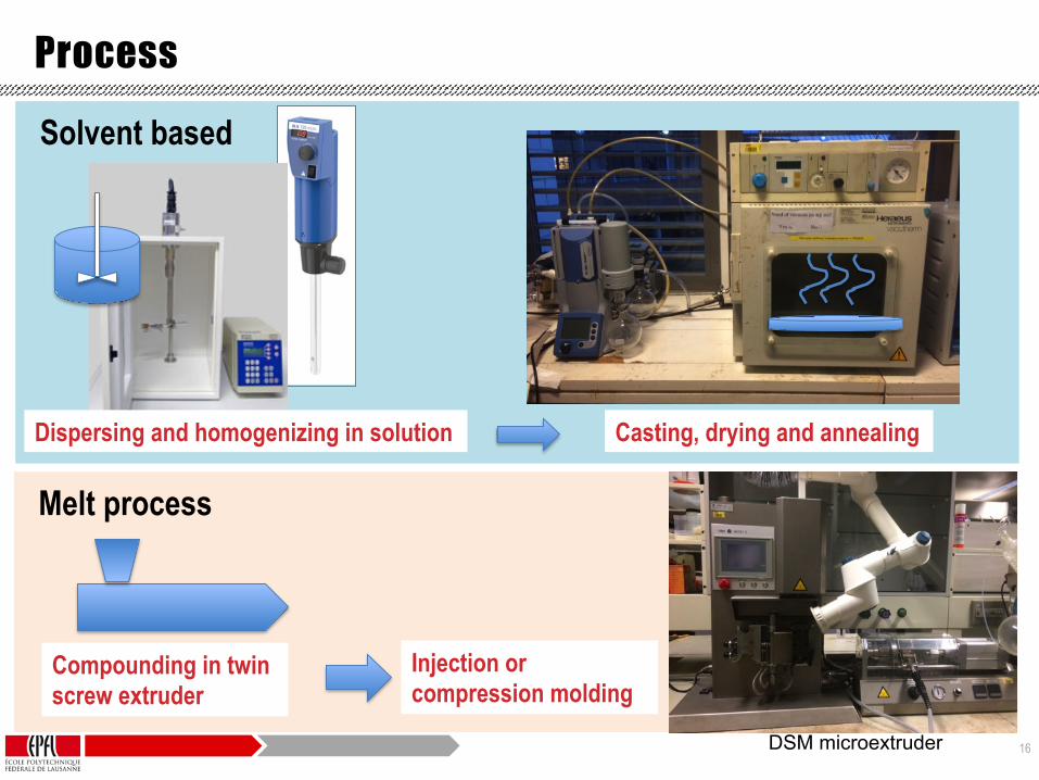
Melt process
Process
Solvent based
Casting, drying and annealing
Compounding in twin screw extruder
Injection or compression molding
DSM microextruder
Dispersing and homogenizing in solution
17
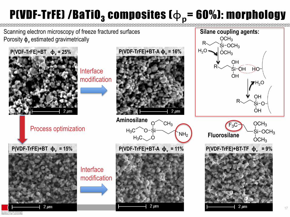
P(VDF-TrFE) /BaTiO3 composites (ϕp= 60%): morphology
P(VDF-TrFE)+BT-A ϕv = 16% P(VDF-TrFE)+BT ϕv = 25%
Scanning electron microscopy of freeze fractured surfaces Porosity ϕv estimated gravimetrically
P(VDF-TrFE)+BT ϕv = 15% P(VDF-TrFE)+BT-TF ϕv = 9% P(VDF-TrFE)+BT-A ϕv = 11%
Process optimization
Interface modification
Interface modification
Aminosilane
Fluorosilane
H2O
H2O
Silane coupling agents:
18
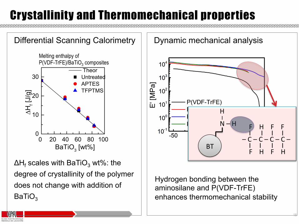
Differential Scanning Calorimetry ΔHf scales with BaTiO3 wt%: the degree of crystallinity of the polymer does not change with addition of BaTiO3
Crystallinity and Thermomechanical properties
Dynamic mechanical analysis
BT
H I N – H F H F F
I I I I – C – C – C – C – I I I I F H F H
Melting enthalpy of P(VDF-TrFE)/BaTiO3 composites
Hydrogen bonding between the aminosilane and P(VDF-TrFE) enhances thermomechanical stability

19
Dielectric and piezoelectric properties
6 mm
Composite with gold electrodes
RelaEve permiRvity and loss factor of P(VDF-‐TrFE)/BaTiO3 composites
d33 of composites poled with Ep = 100 kV/cm

20
P(VDF-TrFE)/BaTiO3 composites
Piezoelectric composites with 60 vol% well dispersed submicron sized ceramic particles: • Storage modulus: 7x increase with respect to P(VDF-TrFE)
• Relative permittivity: 8x increase with respect to P(VDF-TrFE)
• Piezoelectric coefficient: 5x increase with respect to P(VDF-TrFE) with poling field of 100 kV/cm
• Particle surface modification increased thermomechanical stability and decreased dielectric loss factor at low frequency
Research is ongoing to further increase dielectric and piezoelectric properties for practical applications
21
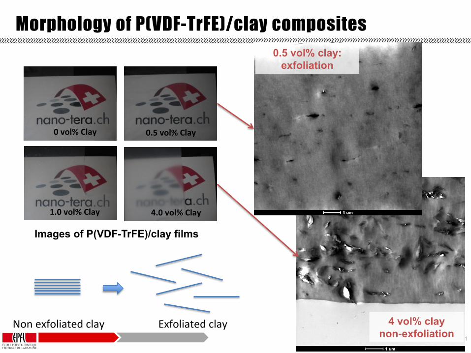
Morphology of P(VDF-TrFE)/clay composites 0.5 vol% clay:
exfoliation
4 vol% clay non-exfoliation
Images of P(VDF-TrFE)/clay films
0.5 vol% Clay
1.0 vol% Clay 4.0 vol% Clay
0 vol% Clay
Non exfoliated clay Exfoliated clay
22
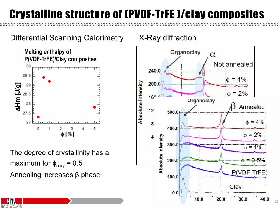
Differential Scanning Calorimetry The degree of crystallinity has a maximum for ϕclay = 0.5
Annealing increases β phase
Crystalline structure of (PVDF-TrFE )/clay composites
Melting enthalpy of P(VDF-TrFE)/Clay composites
X-Ray diffraction

23
0h0.5%1%2%4%CM-20A-0.5%
10 20 30 40 500
100
200
300
400
500
600
0 %
10 20 30 40 50
2h4h16h40h
T (°C)
P (1
06 .cm
3 .cm
/cm
2 .s.P
a)
T (°C)
not annealed annealed
Gas barrier and piezoelectric properties
ϕclay = 0.5 %
O2 permeability of P(VDF-TrFe)/clay composites Piezoelectric coefficient of P(VDF-TrFe)/clay composites
annealed
Gas barrier and piezoelectric properties can be enhanced optimizing annealing time and clay concentration

24
Self-sensing high pressure H2 storage vessel

25
-‐ High barrier properEes -‐> Low permeability material
-‐ Health monitoring and sensing (safety) -‐> “smart structure”
-‐ High pressure to reduce volume -‐> High strength without embriblement
Nanocomposite of PVDF-‐TrFE (poly-‐vinylidene fluoride trifluoroethylene copolymer) with surface modified clay platelet parGcles
+ High strength carbon fiber reinforced composite
piezosensor)and)hydrogen)barrier)membrane)(PVDF))
carbon)fiber)reinforced)polymer)composite)shell)
polyamide)liner)aluminium)connec=on)
4 kg H2 needed to drive a fuel cell car 400 km (45 m3 at ambient -‐> 0.11 m3 at 400 bar) Schlapbach, L. Zübel, A. Hydrogen-‐storage materials for mobile applicaEons, Nature, 414 (2001)
Self-sensing high pressure H2 storage vessel
Commercial H2 storage vessels (thick polymer liner + metal + carbon fiber composites) are expensive and present a risk of H2 embriblement

26
Collaboration EPFL-CSEM on process-structure-property relations in piezoelectric polymer materials
• The Greenpower project combines for the first time a self-sensing liner with a cost-effective composite production process
• Proportion of piezoelectric β-phase in modified P(VDF-TrFE): 95%
• 30% increase in piezoelectric coefficient
• 10x reduction of gas permeation
Copyright 2012 CSEM | XRD Application LAB | Page 5
Figure 5. 3D isolines-view of the patterns obtained during the heating.
0 8 16 24 32 40 48
10°C30°C
50°C40°C
Annealing time [h]
0
100
200
300
400
500
600
0 10 20 30 40 50
0h2h4h16h24h48h
Temperature [°C]
P [1
016 c
m3 c
m c
m-2
s-1
Pa-1
]
0
20
40
60
80
0 20 40 60
A B
Oxygen permeability of modified P(VDF-TrFE)
In-situ XRD analysis of P(VDF-TrFE)
Self-sensing high pressure H2 storage vessel
Oliveira F, et al. (2014)
27
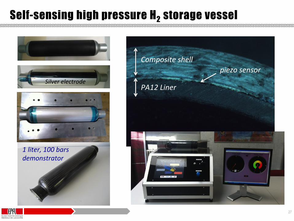
Silver electrode
Composite shell piezo sensor
PA12 Liner
1 liter, 100 bars demonstrator
Self-sensing high pressure H2 storage vessel

28
Conclusions and outlook
• Fluoropolymer based 0-3 composites offer a unique combination of properties and design flexibility for sensing and actuating applications
• Their structure and properties are highly dependent on processing conditions
Practical applications have now become possible… …and research is still ongoing to improve their properties and scale up processes
29
Acknowledgements
LTC – EPFL Ceramics Laboratory – EPFL
Dr. Y. Leterrier Prof. V. Michaud Prof. D. Damjanovic
Dr. F. Oliveira Mr. Robert Tween
Olha Sereda - CSEM
Undergraduate students: S. Poitel, V. Magnin, F. Lindstroem A. Aebersold, D. Chevret, E. Stutz, M. Hausmann, R. Thierrin … Interdisciplinary Centre for Electron Microscopy (CIME-‐EPFL)

30
Thank you!

31
References • Dalle Vacche S, et al. The effect of processing conditions on the morphology, thermomechanical,
dielectric, and piezoelectric properties of P(VDF-TrFE)/BaTiO3 composites. Journal of Materials Science. 2012;47(11):4763-4774.
• Dalle Vacche S, et al. Effect of silane coupling agent on the morphology, structure, and properties of poly(vinylidene fluoride–trifluoroethylene)/BaTiO3 composites. Journal of Materials Science. 2014;49(13):4552-4564.
• Dalle Vacche S, et al. Effect of interfacial interactions on the electromechanical response of poly(vinylidene fluoride-trifluoroethylene)/BaTiO3 composites and its time dependence after poling. Composites Science and Technology. 2015;114:103-109.
• Oliveira F, et al. Process Influences on the Structure, Piezoelectric, and Gas-Barrier Properties of PVDF-TrFE Copolymer. Journal of Polymer Science Part B-Polymer Physics. 2014;52(7):496-506.
• Newnham RE, et al. Connectivity and piezoelectric-pyroelectric composites. Mater Res Bull. 1978;13(5):525-536.
• Daniel Tan and Patricia Irwin (2011). Polymer Based Nanodielectric Composites, Advances in Ceramics -Electric and Magnetic Ceramics, Bioceramics, Ceramics and Environment, Prof. Costas Sikalidis (Ed.), ISBN:978-953-307-350-7, InTech
• Takahashi H, et al. . Considerations for BaTiO3 Ceramics with High Piezoelectric Properties Fabricated by Microwave Sintering Method. Japanese Journal of Applied Physics. 2008;47(11):8468-8471.