Comparison between different chromatic dispersion ... · linear effects on the dispersion...
7
Comparison between different chromatic dispersion compensation schemes in high bit rate communication systems with important non linear effects. LAZOUL MOHAMED (1), SIMOHAMED LOFTY MOKHTAR (1) , BOUDRIOUA AZZEDINE (2) (1) Laboratoire des Systèmes Électroniques et Optroniques. (2) Institut Galilée. (1) Ecole Militaire Polytechnique. (2) Université Paris 13. (1) BP 17 Bordj El Bahri, Algiers (2) Paris. (1) ALGERIA. (2) FRANCE. Abstract: In this work we investigate the performances of a high bit rate communication system, using different chromatic dispersion compensation schemes. The study is carried out in the presence of non linear effects. A comparison between different compensation schemes has been achieved. Key-Words: Chromatic dispersion, self phase modulation, high bit rate communication system, dispersion compensation, pre-compensation, post-compensation, symmetric compensation. 1 Introduction Fundamental investigations have demonstrated the usefulness of SMF (Standard Monomode Fiber) for transmission of bit rate higher than 10 Gb/s over a single-channel [1]. Numerical [2] and experimental [3] studies gave first ideas about the design of an appropriate passive dispersion management schemes for upgrading the existing SMF communication systems. High-speed transmission over SMF at 1.55 μm suffers severely from the combined interaction of Kerr nonlinearity and dispersion. Several techniques have been developed to overcome these limitations. The use of dispersion compensating fibers (DCF) has emerged as one of the most practical techniques to compensate for the chromatic dispersion in long-haul optically amplified standard fiber transmission systems. So far, it has been believed that SPM (Self Phase Modulation) degrades the DCF based system performances [4]. For this reason, previous works have always emphasized the importance of launching a low power into the DCF in order to minimize the SPM effects and to operate the DCF in the linear regime [4]. This paper deals with the performances analysis of a high bit rate communication system, using different chromatic dispersion compensation schemes. The study is carried out in the presence of non linear effects. The performances are expressed by the BER (Bit Error Rate), which is the most commonly used performance quantification factor in digital communications. We investigated the BER penalty induced by the non linear effects on the dispersion compensation system. 2 Theoretical considerations In this paragraph we are going to present first some theoretical aspects concerning pulse propagation in optical fiber and the combined effects of dispersion and SPM. In a second step, different dispersion compensation techniques are going to be described. 2.1 Chromatic dispersion and SPM effects: Neglecting polarization and scattering effects such as stimulated Raman scattering and stimulated Brillouin scattering, propagation of optical pulses in fibers can be described by the Non Linear Schrödinger Equation (NLSE): 2 2 2 2 2 2 A i i A A z T α β γ ⎛ ⎞ ∂ ∂ = − − + ⎜ ⎟ ∂ ∂ ⎝ ⎠ (1) Where A is the slowly varying amplitude of the pulse envelope and g T t z/v = − denotes the time transformation to a frame of reference moving with the group velocity g v . The NLSE describes how linear and non linear phenomena act on the pulse propagation. On the right-hand of Eq. (1) α expresses the fiber losses, 2 β is related to chromatic dispersion and γ is for Kerr nonlinearity parameter. 0 2 1 eff n A c ω γ ⎛ ⎞ ⎛ ⎞ = ⎜ ⎟ ⎜ ⎟ ⎜ ⎟ ⎝ ⎠ ⎝ ⎠ (2) Where 2 n is the non linear index and eff A is the effective fiber core area. The standard values of these parameters are n 2 = 2.6 e-20 m 2 /W and A eff = 80e-12m 2 . The non linearity grows with n 2 increasing, the A eff decreasing and the power increasing. 12th WSEAS International Conference on COMMUNICATIONS, Heraklion, Greece, July 23-25, 2008 ISSN: 1790-5117 110 ISBN: 978-960-6766-84-8
Transcript of Comparison between different chromatic dispersion ... · linear effects on the dispersion...
Comparison between different chromatic dispersion compensation schemes in high bit rate communication systems with important non linear effects.
LAZOUL MOHAMED (1), SIMOHAMED LOFTY MOKHTAR (1), BOUDRIOUA AZZEDINE (2)
(1) Laboratoire des Systèmes Électroniques et Optroniques. (2) Institut Galilée. (1) Ecole Militaire Polytechnique. (2) Université Paris 13.
(1) BP 17 Bordj El Bahri, Algiers (2) Paris. (1) ALGERIA. (2) FRANCE.
Abstract: In this work we investigate the performances of a high bit rate communication system, using different chromatic dispersion compensation schemes. The study is carried out in the presence of non linear effects. A comparison between different compensation schemes has been achieved. Key-Words: Chromatic dispersion, self phase modulation, high bit rate communication system, dispersion compensation, pre-compensation, post-compensation, symmetric compensation. 1 Introduction Fundamental investigations have demonstrated the usefulness of SMF (Standard Monomode Fiber) for transmission of bit rate higher than 10 Gb/s over a single-channel [1]. Numerical [2] and experimental [3] studies gave first ideas about the design of an appropriate passive dispersion management schemes for upgrading the existing SMF communication systems. High-speed transmission over SMF at 1.55 µm suffers severely from the combined interaction of Kerr nonlinearity and dispersion. Several techniques have been developed to overcome these limitations. The use of dispersion compensating fibers (DCF) has emerged as one of the most practical techniques to compensate for the chromatic dispersion in long-haul optically amplified standard fiber transmission systems. So far, it has been believed that SPM (Self Phase Modulation) degrades the DCF based system performances [4]. For this reason, previous works have always emphasized the importance of launching a low power into the DCF in order to minimize the SPM effects and to operate the DCF in the linear regime [4]. This paper deals with the performances analysis of a high bit rate communication system, using different chromatic dispersion compensation schemes. The study is carried out in the presence of non linear effects. The performances are expressed by the BER (Bit Error Rate), which is the most commonly used performance quantification factor in digital communications. We investigated the BER penalty induced by the non linear effects on the dispersion compensation system. 2 Theoretical considerations In this paragraph we are going to present first some theoretical aspects concerning pulse propagation in
optical fiber and the combined effects of dispersion and SPM. In a second step, different dispersion compensation techniques are going to be described. 2.1 Chromatic dispersion and SPM effects: Neglecting polarization and scattering effects such as stimulated Raman scattering and stimulated Brillouin scattering, propagation of optical pulses in fibers can be described by the Non Linear Schrödinger Equation (NLSE):
22
2 22 2A i
i A Az T
α β γ⎛ ⎞∂ ∂
= − − +⎜ ⎟∂ ∂⎝ ⎠ (1)
Where A is the slowly varying amplitude of the pulse envelope and gT t z / v= − denotes the time transformation to a frame of reference moving with the group velocity gv . The NLSE describes how linear and non linear phenomena act on the pulse propagation. On the right-hand of Eq. (1) α expresses the fiber losses,
2β is related to chromatic dispersion and γ is for Kerr nonlinearity parameter.
02
1
eff
nA c
ωγ⎛ ⎞⎛ ⎞= ⎜ ⎟⎜ ⎟⎜ ⎟⎝ ⎠⎝ ⎠
(2)
Where 2n is the non linear index and effA is the effective fiber core area. The standard values of these parameters are n2 = 2.6 e-20 m2/W and Aeff = 80e-12m2. The non linearity grows with n2 increasing, the Aeff decreasing and the power increasing.
12th WSEAS International Conference on COMMUNICATIONS, Heraklion, Greece, July 23-25, 2008
ISSN: 1790-5117 110 ISBN: 978-960-6766-84-8
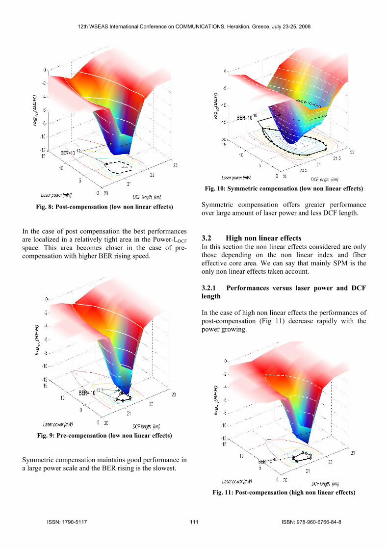
Fig. 8: Post-compensation (low non linear effects)
In the case of post compensation the best performances are localized in a relatively tight area in the Power-LDCF space. This area becomes closer in the case of pre-compensation with higher BER rising speed.
Fig. 9: Pre-compensation (low non linear effects)
Symmetric compensation maintains good performance in a large power scale and the BER rising is the slowest.
Fig. 10: Symmetric compensation (low non linear effects)
Symmetric compensation offers greater performance over large amount of laser power and less DCF length. 3.2 High non linear effects In this section the non linear effects considered are only those depending on the non linear index and fiber effective core area. We can say that mainly SPM is the only non linear effects taken account. 3.2.1 Performances versus laser power and DCF length In the case of high non linear effects the performances of post-compensation (Fig 11) decrease rapidly with the power growing.
Fig. 11: Post-compensation (high non linear effects)
12th WSEAS International Conference on COMMUNICATIONS, Heraklion, Greece, July 23-25, 2008
ISSN: 1790-5117 111 ISBN: 978-960-6766-84-8
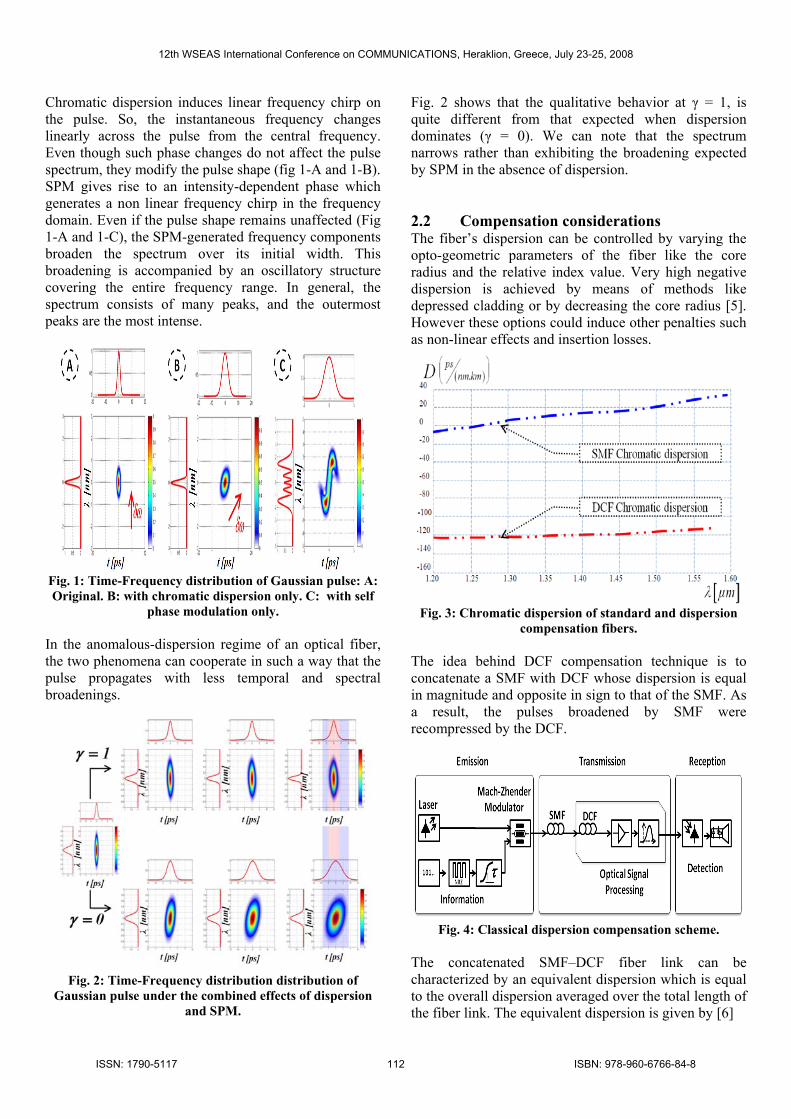
Chromatic dispersion induces linear frequency chirp on the pulse. So, the instantaneous frequency changes linearly across the pulse from the central frequency. Even though such phase changes do not affect the pulse spectrum, they modify the pulse shape (fig 1-A and 1-B). SPM gives rise to an intensity-dependent phase which generates a non linear frequency chirp in the frequency domain. Even if the pulse shape remains unaffected (Fig 1-A and 1-C), the SPM-generated frequency components broaden the spectrum over its initial width. This broadening is accompanied by an oscillatory structure covering the entire frequency range. In general, the spectrum consists of many peaks, and the outermost peaks are the most intense.
Fig. 1: Time-Frequency distribution of Gaussian pulse: A: Original. B: with chromatic dispersion only. C: with self
phase modulation only. In the anomalous-dispersion regime of an optical fiber, the two phenomena can cooperate in such a way that the pulse propagates with less temporal and spectral broadenings.
Fig. 2: Time-Frequency distribution distribution of
Gaussian pulse under the combined effects of dispersion and SPM.
Fig. 2 shows that the qualitative behavior at γ = 1, is quite different from that expected when dispersion dominates (γ = 0). We can note that the spectrum narrows rather than exhibiting the broadening expected by SPM in the absence of dispersion. 2.2 Compensation considerations The fiber’s dispersion can be controlled by varying the opto-geometric parameters of the fiber like the core radius and the relative index value. Very high negative dispersion is achieved by means of methods like depressed cladding or by decreasing the core radius [5]. However these options could induce other penalties such as non-linear effects and insertion losses.
Fig. 3: Chromatic dispersion of standard and dispersion
compensation fibers. The idea behind DCF compensation technique is to concatenate a SMF with DCF whose dispersion is equal in magnitude and opposite in sign to that of the SMF. As a result, the pulses broadened by SMF were recompressed by the DCF.
Fig. 4: Classical dispersion compensation scheme.
The concatenated SMF–DCF fiber link can be characterized by an equivalent dispersion which is equal to the overall dispersion averaged over the total length of the fiber link. The equivalent dispersion is given by [6]
12th WSEAS International Conference on COMMUNICATIONS, Heraklion, Greece, July 23-25, 2008
ISSN: 1790-5117 112 ISBN: 978-960-6766-84-8

Fig. 8: Post-compensation (low non linear effects)
In the case of post compensation the best performances are localized in a relatively tight area in the Power-LDCF space. This area becomes closer in the case of pre-compensation with higher BER rising speed.
Fig. 9: Pre-compensation (low non linear effects)
Symmetric compensation maintains good performance in a large power scale and the BER rising is the slowest.
Fig. 10: Symmetric compensation (low non linear effects)
Symmetric compensation offers greater performance over large amount of laser power and less DCF length. 3.2 High non linear effects In this section the non linear effects considered are only those depending on the non linear index and fiber effective core area. We can say that mainly SPM is the only non linear effects taken account. 3.2.1 Performances versus laser power and DCF length In the case of high non linear effects the performances of post-compensation (Fig 11) decrease rapidly with the power growing.
Fig. 11: Post-compensation (high non linear effects)
12th WSEAS International Conference on COMMUNICATIONS, Heraklion, Greece, July 23-25, 2008
ISSN: 1790-5117 113 ISBN: 978-960-6766-84-8
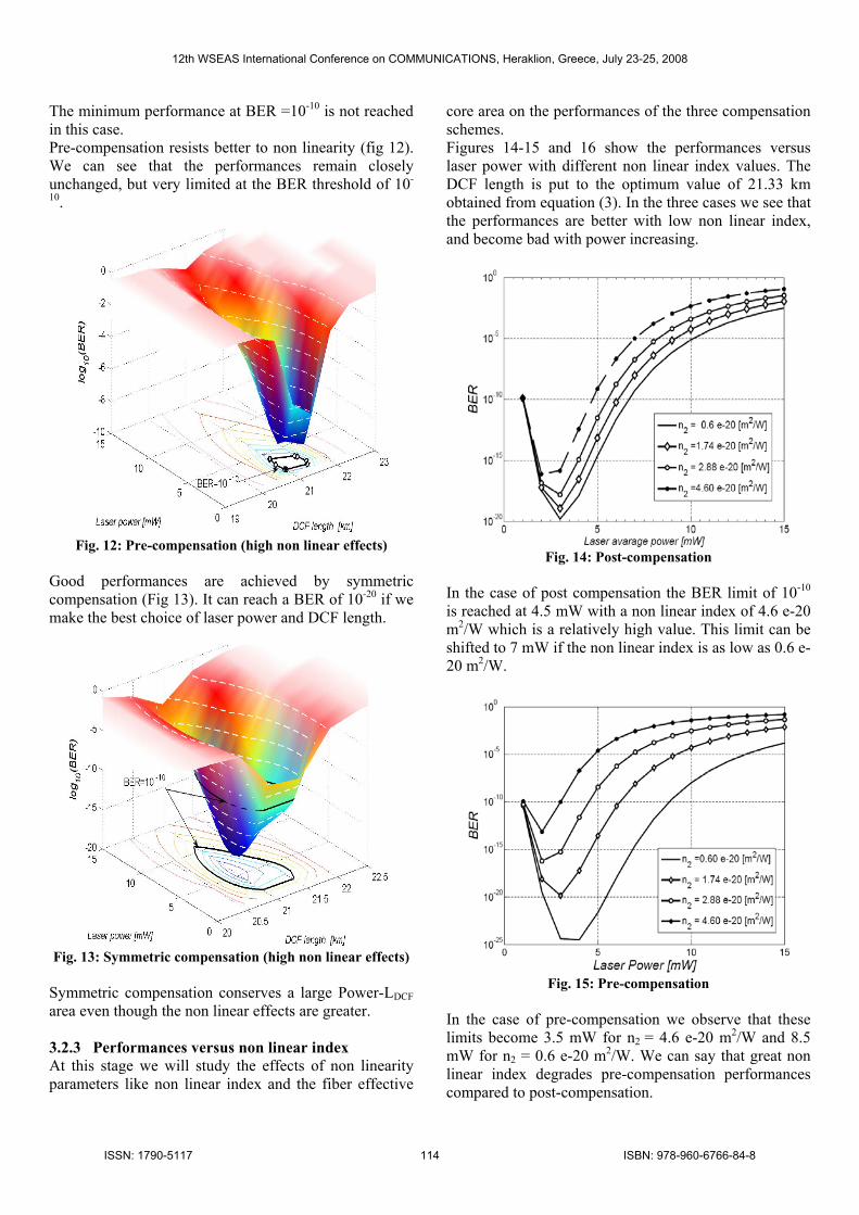
The minimum performance at BER =10-10 is not reached in this case. Pre-compensation resists better to non linearity (fig 12). We can see that the performances remain closely unchanged, but very limited at the BER threshold of 10-
10.
Fig. 12: Pre-compensation (high non linear effects)
Good performances are achieved by symmetric compensation (Fig 13). It can reach a BER of 10-20 if we make the best choice of laser power and DCF length.
Fig. 13: Symmetric compensation (high non linear effects)
Symmetric compensation conserves a large Power-LDCF area even though the non linear effects are greater. 3.2.3 Performances versus non linear index At this stage we will study the effects of non linearity parameters like non linear index and the fiber effective
core area on the performances of the three compensation schemes. Figures 14-15 and 16 show the performances versus laser power with different non linear index values. The DCF length is put to the optimum value of 21.33 km obtained from equation (3). In the three cases we see that the performances are better with low non linear index, and become bad with power increasing.
Fig. 14: Post-compensation
In the case of post compensation the BER limit of 10-10 is reached at 4.5 mW with a non linear index of 4.6 e-20 m2/W which is a relatively high value. This limit can be shifted to 7 mW if the non linear index is as low as 0.6 e-20 m2/W.
Fig. 15: Pre-compensation
In the case of pre-compensation we observe that these limits become 3.5 mW for n2 = 4.6 e-20 m2/W and 8.5 mW for n2 = 0.6 e-20 m2/W. We can say that great non linear index degrades pre-compensation performances compared to post-compensation.
12th WSEAS International Conference on COMMUNICATIONS, Heraklion, Greece, July 23-25, 2008
ISSN: 1790-5117 114 ISBN: 978-960-6766-84-8
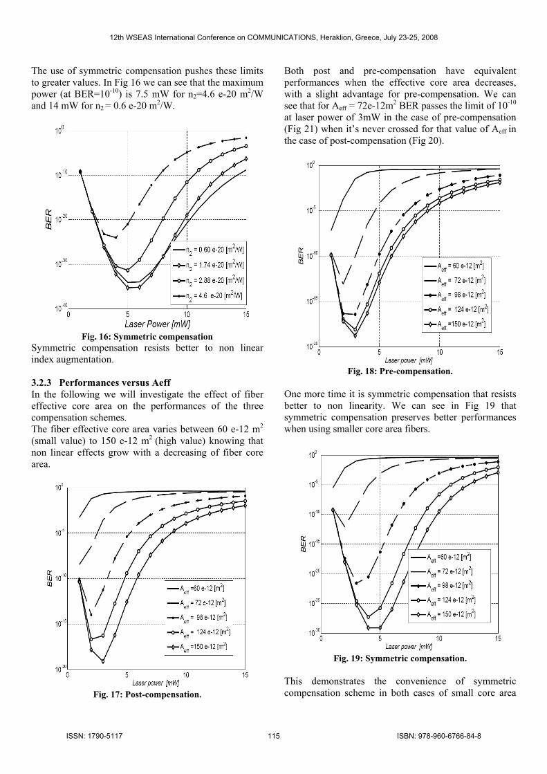
The use of symmetric compensation pushes these limits to greater values. In Fig 16 we can see that the maximum power (at BER=10-10) is 7.5 mW for n2=4.6 e-20 m2/W and 14 mW for n2 = 0.6 e-20 m2/W.
Fig. 16: Symmetric compensation
Symmetric compensation resists better to non linear index augmentation. 3.2.3 Performances versus Aeff In the following we will investigate the effect of fiber effective core area on the performances of the three compensation schemes. The fiber effective core area varies between 60 e-12 m2 (small value) to 150 e-12 m2 (high value) knowing that non linear effects grow with a decreasing of fiber core area.
Fig. 17: Post-compensation.
Both post and pre-compensation have equivalent performances when the effective core area decreases, with a slight advantage for pre-compensation. We can see that for Aeff = 72e-12m2 BER passes the limit of 10-10 at laser power of 3mW in the case of pre-compensation (Fig 21) when it’s never crossed for that value of Aeff in the case of post-compensation (Fig 20).
Fig. 18: Pre-compensation.
One more time it is symmetric compensation that resists better to non linearity. We can see in Fig 19 that symmetric compensation preserves better performances when using smaller core area fibers.
Fig. 19: Symmetric compensation.
This demonstrates the convenience of symmetric compensation scheme in both cases of small core area
12th WSEAS International Conference on COMMUNICATIONS, Heraklion, Greece, July 23-25, 2008
ISSN: 1790-5117 115 ISBN: 978-960-6766-84-8
fibers or large core area fibers which are used in DWDM (Dense Wavelength Division Multiplexing) systems.
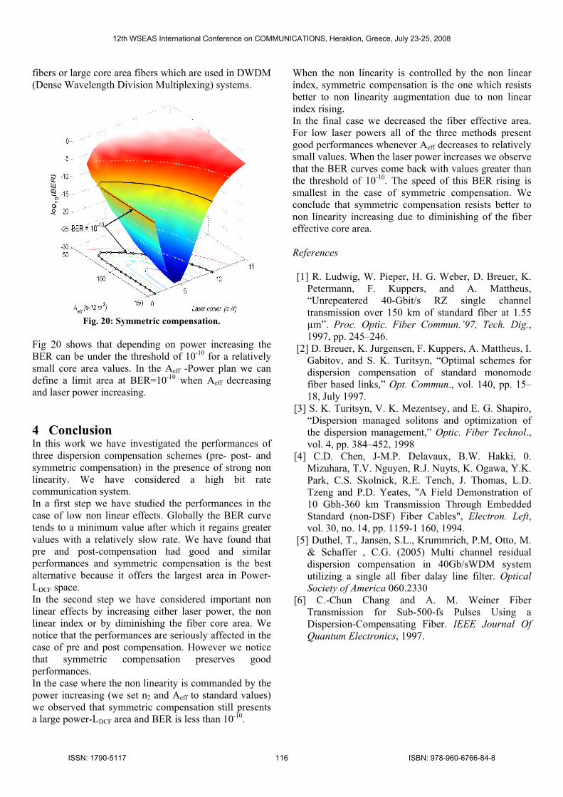
Fig. 20: Symmetric compensation.
Fig 20 shows that depending on power increasing the BER can be under the threshold of 10-10 for a relatively small core area values. In the Aeff -Power plan we can define a limit area at BER=10-10 when Aeff decreasing and laser power increasing. 4 Conclusion In this work we have investigated the performances of three dispersion compensation schemes (pre- post- and symmetric compensation) in the presence of strong non linearity. We have considered a high bit rate communication system. In a first step we have studied the performances in the case of low non linear effects. Globally the BER curve tends to a minimum value after which it regains greater values with a relatively slow rate. We have found that pre and post-compensation had good and similar performances and symmetric compensation is the best alternative because it offers the largest area in Power-LDCF space. In the second step we have considered important non linear effects by increasing either laser power, the non linear index or by diminishing the fiber core area. We notice that the performances are seriously affected in the case of pre and post compensation. However we notice that symmetric compensation preserves good performances. In the case where the non linearity is commanded by the power increasing (we set n2 and Aeff to standard values) we observed that symmetric compensation still presents a large power-LDCF area and BER is less than 10-10.
When the non linearity is controlled by the non linear index, symmetric compensation is the one which resists better to non linearity augmentation due to non linear index rising. In the final case we decreased the fiber effective area. For low laser powers all of the three methods present good performances whenever Aeff decreases to relatively small values. When the laser power increases we observe that the BER curves come back with values greater than the threshold of 10-10. The speed of this BER rising is smallest in the case of symmetric compensation. We conclude that symmetric compensation resists better to non linearity increasing due to diminishing of the fiber effective core area. References [1] R. Ludwig, W. Pieper, H. G. Weber, D. Breuer, K.
Petermann, F. Kuppers, and A. Mattheus, “Unrepeatered 40-Gbit/s RZ single channel transmission over 150 km of standard fiber at 1.55 µm”. Proc. Optic. Fiber Commun.’97, Tech. Dig., 1997, pp. 245–246.
[2] D. Breuer, K. Jurgensen, F. Kuppers, A. Mattheus, I. Gabitov, and S. K. Turitsyn, “Optimal schemes for dispersion compensation of standard monomode fiber based links,” Opt. Commun., vol. 140, pp. 15–18, July 1997.
[3] S. K. Turitsyn, V. K. Mezentsey, and E. G. Shapiro, “Dispersion managed solitons and optimization of the dispersion management,” Optic. Fiber Technol., vol. 4, pp. 384–452, 1998
[4] C.D. Chen, J-M.P. Delavaux, B.W. Hakki, 0. Mizuhara, T.V. Nguyen, R.J. Nuyts, K. Ogawa, Y.K. Park, C.S. Skolnick, R.E. Tench, J. Thomas, L.D. Tzeng and P.D. Yeates, "A Field Demonstration of 10 Gbh-360 km Transmission Through Embedded Standard (non-DSF) Fiber Cables", Electron. Left, vol. 30, no. 14, pp. 1159-1 160, 1994.
[5] Duthel, T., Jansen, S.L., Krummrich, P.M, Otto, M. & Schaffer , C.G. (2005) Multi channel residual dispersion compensation in 40Gb/sWDM system utilizing a single all fiber dalay line filter. Optical Society of America 060.2330
[6] C.-Chun Chang and A. M. Weiner Fiber Transmission for Sub-500-fs Pulses Using a Dispersion-Compensating Fiber. IEEE Journal Of Quantum Electronics, 1997.
12th WSEAS International Conference on COMMUNICATIONS, Heraklion, Greece, July 23-25, 2008
ISSN: 1790-5117 116 ISBN: 978-960-6766-84-8


![Interface Examen · 1. Format Text C] 2. Format Paragraph Format the Specified te The text "Saturn is • BOId 2 Format Paragraph 3. Modity Style Wo,d 2013 ormat the specified paragraph.](https://static.fdocuments.fr/doc/165x107/5e1fe80d7ca6836b1d247b35/interface-1-format-text-c-2-format-paragraph-format-the-specified-te-the-text.jpg)