CITY2+ CITY2+L CITY2+ BC - Ellardcentrale di comando (24v) digitale per cancelli ad anta e...
25
ZIS193 IL 291-1 EDIZ. 18/03/2019 I GB F E CENTRALE DI COMANDO (24V) DIGITALE PER CANCELLI AD ANTA E SCORREVOLI DIGITAL CONTROL UNIT (24V) FOR LEAF SWING AND SLIDING GATES ARMOIRE DE COMMANDE NUMÉRIQUE (24V) POUR PORTAILS À VANTAILS ET COULISSANTS CUADRO DE MANIOBRAS DIGITAL (24V) PARA CANCELAS BATIENTES Y PUERTAS CORREDERAS CITY2+ CITY2+L CITY2+ BC
Transcript of CITY2+ CITY2+L CITY2+ BC - Ellardcentrale di comando (24v) digitale per cancelli ad anta e...
ZIS193IL 291-1EDIZ. 18/03/2019
I
GB
F
E
CENTRALE DI COMANDO (24V) DIGITALE PER CANCELLI AD ANTA E SCORREVOLI
DIGITAL CONTROL UNIT (24V) FOR LEAF SWING AND SLIDING GATES
ARMOIRE DE COMMANDE NUMÉRIQUE (24V) POUR PORTAILS À VANTAILS ET COULISSANTS
CUADRO DE MANIOBRAS DIGITAL (24V) PARA CANCELAS BATIENTES Y PUERTAS CORREDERAS
CITY2+CITY2+LCITY2+ BC


EN
GLIS
H
- 23 -
INDEX
1 - IMPORTANT REMARKS .........................................................................................................................................
2 - DECLARATION OF CONFORMITY .........................................................................................................................
3 - TECHNICAL SPECIFICATIONS ................................................................................................................................
4 - DESCRIPTION OF THE CONTROL UNIT .................................................................................................................
5 - INSTALLATION .......................................................................................................................................................
5.1 - POWER SUPPLY ...............................................................................................................................................
5.2 - MOTORS .........................................................................................................................................................
5.3 - ACTIVATION INPUTS ........................................................................................................................................
5.4 - STOP ...............................................................................................................................................................
5.5 - PHOTOCELLS ..................................................................................................................................................
5.6 - SAFETY RIBBONS ............................................................................................................................................
5.7 - LOW VOLTAGE LIGHT (24V) ............................................................................................................................
5.8 - 230V COURTESY LIGHT OR FLASHING LIGHT ..................................................................................................
5.9 - LOCK ..............................................................................................................................................................
5.10 - LIMIT SWITCH AND ENCODER ......................................................................................................................
5.11 - EXTERNAL AERIAL .........................................................................................................................................
5.12 - PLUG IN RECEIVER ........................................................................................................................................
5.13 - ADI INTERFACE .............................................................................................................................................
5.14 - ELECTRIC CONNECTIONS ..............................................................................................................................
6 - CONTROL PANEL ...................................................................................................................................................
6.1 - USE OF THE DOWN, MENU AND UP KEYS FOR PROGRAMMING .....................................................................
7 - QUICK CONFIGURATION .......................................................................................................................................
8 - LOADING OF DEFAULT PARAMETERS ..................................................................................................................
9 - SELF-LEARNING OF WORKING TIMES ..................................................................................................................
10 - READING OF CYCLE COUNTER ...........................................................................................................................
10.1 - SIGNAL OF SERVICE REQUIRED .....................................................................................................................
11 - CONTROL UNIT CONFIGURATION ......................................................................................................................
12 - OPERATION DEFECTS ..........................................................................................................................................
24
24
24
25
25
25
25
26
26
26
27
27
27
27
28
29
29
29
30
32
32
33
33
34
35
35
36
43
EN
GLI
SH
- 24 -
1 - IMPORTANT REMARKS
For any installation problem please contact our Customer Service at the number +39-0172.812411 operating Monday to Friday from 8:30 to 12:30 and from 14:00 to 18:00.
V2 has the right to modify the product without previous notice; it also declines any responsibility to damage or injury to people or things caused by improper use or wrong installation.
m Please read this instruction manual very carefully before installing and programming your control unit.
• This instruction manual is only for qualified technicians, who specialize in installations and automations.
• The contents of this instruction manual do not concern the end user.
• Every programming and/or every maintenance service should be done only by qualified technicians.
AUTOMATION MUST BE IMPLEMENTED IN COMPLIANCE WITH THE EUROPEAN REGULATIONS IN FORCE:
EN 60204-1 (Machinery safety. electrical equipment of machines, part 1: general rules) EN 12445 (Safe use of automated locking devices, test methods)EN 12453 (Safe use of automated locking devices, requirements)
• The installer must provide for a device (es. magnetotermical switch) ensuring the omnipolar sectioning of the equipment from the power supply. The standards require a separation of the contacts of at least 3 mm in each pole (EN 60335-1).
• After making connections on the terminal board, use one hose clamp to fix dangerous voltage wires near the terminal board and another hose clamp to fix safety low voltage wires used for accessories connection; this way, in case of accidental detachment of a conducting wire, dangerous voltage parts will not come into contact with safety low voltage ones.
• The plastic case has an IP55 insulation; to connect flexible or rigid pipes, use pipefittings having the same insulation level.
• Installation requires mechanical and electrical skills, therefore it shall be carried out by qualified personnel only, who can issue the Compliance Certificate concerning the whole installation (EEC Machine Directive 89/392, Annex IIA).
• The automated vehicular gates shall comply with the following rules: EN 12453, EN 12445, EN 12978 as well as any local rule in force.
• Also the automation upstream electric system shall comply with the laws and rules in force and be carried out workmanlike.
• The door thrust force adjustment shall be measured by means of a proper tool and adjusted according to the max. limits, which EN 12453 allows.
• We recommend to make use of an emergency button, to be installed by the automation (connected to the control unit STOP input) so that the gate may be immediately stopped in case of danger.
• Always remember to connect the earth according to current standards (EN 60335-1, EN 60204-1).
2 - DECLARATION OF CONFORMITY
V2 S.p.A. hereby declare that CITY2+ products conform to the essential requirements established in the following directives:
• 2014/30/UE (EMC Directive)• 2014/35/UE (Low Voltage Directive)• ROHS2 2011/65/CE
Racconigi, 01/06/2015V2 S.p.A. legal representative.Antonio Livio Costamagna
3 - TECHNICAL SPECIFICATIONS
CITY2+ CITY2+L CITY2+BC
Power supply 230V / 50Hz 230V / 50Hz ECO-LOGIC
Maximum load consumed from the mains with two motors + accessories
250W 150W 250W
Nominal load for each motor output
80W 60W 80W
Max accessories load 24Vdc
7W 7W 7W
Work cycle (*) 80% 60% 80%
Protection fuse 2,5A 2,5A -
Weight 3000 g 1000 g 1000 g
Dimensions 295 x 230 x 100 mm
Working temperature
-20 ÷ +60°C
Protection IP55
(*) the work cycle is related to the following conditions:2 motors @ nominal load Room temperature = 25°C
EN
GLIS
H
- 25 -
4 - DESCRIPTION OF THE CONTROL UNIT
The digital control unit CITY2+ is an innovative V2 product that guarantees a safe and reliable automation of leaf swing or sliding gates.
CITY2+ is provided with a display that, not only makes programming simple, but also allows a continuous monitoring of the input statuses; in addition, thanks to a menu structure, the working schedule and the operation logic can be set easily.
In compliance with the European standards concerning electrical safety and electromagnetic compatibility (EN 60335-1, EN 50081-1 and EN 50082-1) it has been equipped with the low voltage circuit total electric insulation (motors included) from the network voltage.
Other characteristics:
• Power supply protected from short circuits within the controller, on the motors and on the connected accessories
• Adjustment of the power by partializing the current
• Detecting obstacles by monitoring the current on the motors (current sensing probe)
• Automatic learning of the operation time.
• Tests for safety devices (photocells, safety ribbons and mosfet) before each opening.
• Deactivation of safety inputs through the configuration menu: no jumper is required for terminals concerning safety devices that have not been installed, yet. You will only need to disable this function from its relevant menu.
• The device can operate without mains power, by using the optional battery pack (code 161212).
• Low voltage output that can be used for a signal light or a 24 V flashing light.
• Auxiliary relay with programmable logic for courtesy light, flashing light or other use.
• ENERGY SAVING FUNCTION
5 - INSTALLATION
Installation of control unit and safety devices must be carried out with power disconnected.
5.1 - POWER SUPPLY
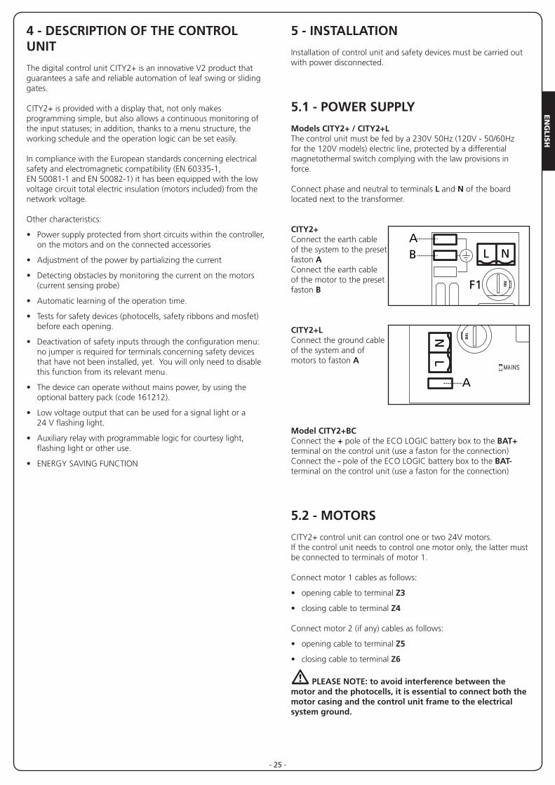
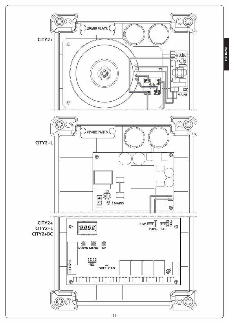
Models CITY2+ / CITY2+L The control unit must be fed by a 230V 50Hz (120V - 50/60Hz for the 120V models) electric line, protected by a differential magnetothermal switch complying with the law provisions in force.
Connect phase and neutral to terminals L and N of the board located next to the transformer.
CITY2+Connect the earth cable of the system to the preset faston AConnect the earth cable of the motor to the preset faston B
CITY2+LConnect the ground cable of the system and of motors to faston A
Model CITY2+BC Connect the + pole of the ECO LOGIC battery box to the BAT+ terminal on the control unit (use a faston for the connection)Connect the - pole of the ECO LOGIC battery box to the BAT- terminal on the control unit (use a faston for the connection)
5.2 - MOTORS
CITY2+ control unit can control one or two 24V motors. If the control unit needs to control one motor only, the latter must be connected to terminals of motor 1.
Connect motor 1 cables as follows:
• opening cable to terminal Z3
• closing cable to terminal Z4
Connect motor 2 (if any) cables as follows:
• opening cable to terminal Z5
• closing cable to terminal Z6
m PLEASE NOTE: to avoid interference between the motor and the photocells, it is essential to connect both the motor casing and the control unit frame to the electrical system ground.
F1
MAINS
L NAB
LN
A
F1

EN
GLI
SH
- 26 -
5.4 - STOP
For a better safety, you can fit a stop switch that will cause the immediate gate stop when activated. This switch must have a normally close contact that will get open in case of operation.In case the stop switch is operated while the gate is open, the automatic closing function will always be disabled. To close the gate again, you will need a start command (if the start function in pause is disabled, it will be temporarily enabled to allow the gate release).
Connect the stop switch cables between terminal L5 (STOP) and L6 (COM) of the control unit.
The stop switch function can be activated by means of a remote control stored on channel 3 (see relevant instructions of MR receiver). The command STOP from remote is operative also if the input STOP of the terminal board is disabled.
5.5 - PHOTOCELLS
The control unit considers two kinds of photocells, depending on the terminal to which they are connected:
Photocell 1Photocells installed on the gate inner side, which are active both during the opening and the closing phase. When photocells 1 operate, the control unit stops the gate; as soon as the photocell beam is free, the control unit will open the gate completely.
m WARNING: Type 1 photocells must be installed so that they completely cover the opening area of the gate.
Photocell 2Photocells installed on the external gate side and which are active during the closing phase only. When photocells 2 operate, the control unit opens the gate immediately, without waiting for release.
CITY2+ control unit supplies a 24Vdc power supply to photocells and it can perform a photocell operation test before starting the gate opening phase. Photocell power terminals are protected by an electronic fuse that stops current in case of overload.
m PLEASE NOTE: it is recommended that the cable ducts used for the motor cables NOT BE USED for the cables connecting the photocells.
• Connect power supply cables of photocells transmitter between terminals K7 (-) and K8 (+Test) of the control unit.
• Connect power supply cables of photocells receiver between terminals K6 (+) and K7 (-) of the control unit.
• Connect receiver output of photocells 1 between terminals L7 (PHOTO1) and L11 (COM) of the control unit and receiver output of photocells 2 between terminals L8 (PHOTO2) and L11 (COM) of the control unit. Use outputs having normally closed contact.
m WARNING:
• if several couples of same kind photocells are mounted, their outputs must be connected in series.
• In case of reflection photocells, power supply must be connected to terminals K7 (-) and K8 (+Test) of the control unit to carry out the operation test.
5.3 - ACTIVATION INPUTS
CITY2+ control unit is equipped with two activation inputs(START and START P.), whose operation depends on the programmed operation modes (see Strtitem of programmingmenu)
Standard modeSTART = START (a command will cause the completeopening of the gate)START P. = PEDESTRIAN START (a command will cause thepartial opening of the gate)
Open/Close commandSTART = OPENING (always controls the gate opening)START P. = CLOSING (always controls the gate closing)This is an impulse command, that is to say that an impulsewill cause the complete gate opening or closing.
Dead man operationSTART = OPENING (always controls the gate opening)START P. = CLOSING (always controls the gate closing)This is a monostable command, that is to say, the gate willbe opened or closed as long as the contact is closed and itwill immediately stop as the contact is open
Timer modeThis function allows programming the gate opening time during the day, by making use of an external timer.
START = START (a command will cause the complete opening of the gate)START P. = PEDESTRIAN START (a command will cause the partial opening of the gate)
The gate stays open (completely or partially) while the contact is closed on input; as soon as the contact is open the pause time count down will start, after which the gate will be closed again.
m ATTENTION: Automatic closing must be enabled.
NOTE: in all modes, inputs must be connected to devices having normally open contacts.
Connect cables of device controlling the first input between terminals L3 (START) and L6 (COM) of the control unit.Connect cables of device controlling the second input between terminals L4 (START P.) and L6 (COM) of the control unit.
The first input function can also be activated by pressing UP key outside the programming menu or by means of a remote control stored on channel 1 (see relevant instructions of MR receiver).
The second input function can also be activated by pressing DOWN key outside the programming menu or by means of a remote control stored on channel 2.
EN
GLIS
H
- 27 -
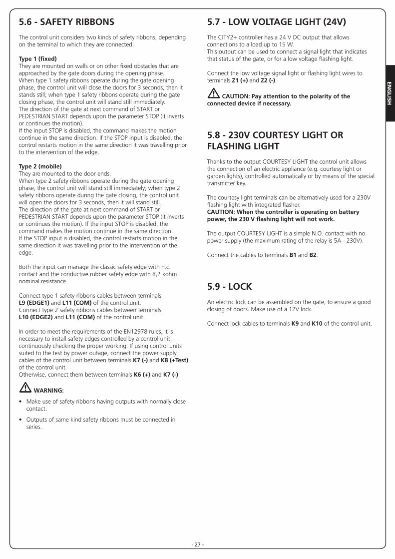
5.7 - LOW VOLTAGE LIGHT (24V)
The CITY2+ controller has a 24 V DC output that allows connections to a load up to 15 W.This output can be used to connect a signal light that indicates that status of the gate, or for a low voltage flashing light.
Connect the low voltage signal light or flashing light wires to terminals Z1 (+) and Z2 (-).
m CAUTION: Pay attention to the polarity of the connected device if necessary.
5.8 - 230V COURTESY LIGHT OR FLASHING LIGHT
Thanks to the output COURTESY LIGHT the control unit allows the connection of an electric appliance (e.g. courtesy light or garden lights), controlled automatically or by means of the special transmitter key.
The courtesy light terminals can be alternatively used for a 230V flashing light with integrated flasher.CAUTION: When the controller is operating on battery power, the 230 V flashing light will not work.
The output COURTESY LIGHT is a simple N.O. contact with nopower supply (the maximum rating of the relay is 5A - 230V).
Connect the cables to terminals B1 and B2.
5.9 - LOCK
An electric lock can be assembled on the gate, to ensure a good closing of doors. Make use of a 12V lock.
Connect lock cables to terminals K9 and K10 of the control unit.
5.6 - SAFETY RIBBONS
The control unit considers two kinds of safety ribbons, depending on the terminal to which they are connected:
Type 1 (fixed)They are mounted on walls or on other fixed obstacles that are approached by the gate doors during the opening phase. When type 1 safety ribbons operate during the gate opening phase, the control unit will close the doors for 3 seconds, then it stands still; when type 1 safety ribbons operate during the gate closing phase, the control unit will stand still immediately. The direction of the gate at next command of START or PEDESTRIAN START depends upon the parameter STOP (it inverts or continues the motion). If the input STOP is disabled, the command makes the motion continue in the same direction. If the STOP input is disabled, the control restarts motion in the same direction it was travelling prior to the intervention of the edge.
Type 2 (mobile)They are mounted to the door ends.When type 2 safety ribbons operate during the gate opening phase, the control unit will stand still immediately; when type 2 safety ribbons operate during the gate closing, the control unit will open the doors for 3 seconds, then it will stand still. The direction of the gate at next command of START or PEDESTRIAN START depends upon the parameter STOP (it inverts or continues the motion). If the input STOP is disabled, the command makes the motion continue in the same direction. If the STOP input is disabled, the control restarts motion in the same direction it was travelling prior to the intervention of the edge.
Both the input can manage the classic safety edge with n.c. contact and the conductive rubber safety edge with 8,2 kohm nominal resistance.
Connect type 1 safety ribbons cables between terminals L9 (EDGE1) and L11 (COM) of the control unit.Connect type 2 safety ribbons cables between terminals L10 (EDGE2) and L11 (COM) of the control unit.
In order to meet the requirements of the EN12978 rules, it is necessary to install safety edges controlled by a control unit continuously checking the proper working. If using control units suited to the test by power outage, connect the power supply cables of the control unit between terminals K7 (-) and K8 (+Test) of the control unit. Otherwise, connect them between terminals K6 (+) and K7 (-).
m WARNING:
• Make use of safety ribbons having outputs with normally close contact.
• Outputs of same kind safety ribbons must be connected in series.
EN
GLI
SH
- 28 -
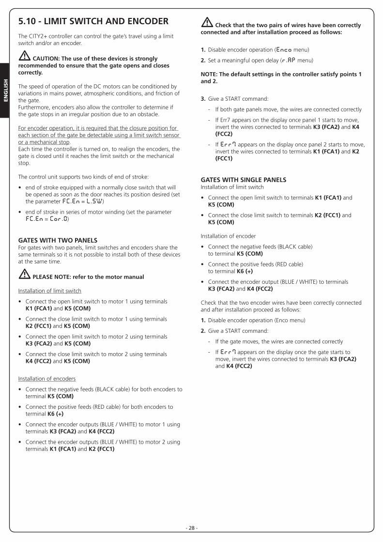
5.10 - LIMIT SWITCH AND ENCODER
The CITY2+ controller can control the gate’s travel using a limit switch and/or an encoder.
m CAUTION: The use of these devices is strongly recommended to ensure that the gate opens and closes correctly.
The speed of operation of the DC motors can be conditioned by variations in mains power, atmospheric conditions, and friction of the gate.Furthermore, encoders also allow the controller to determine if the gate stops in an irregular position due to an obstacle.
For encoder operation, it is required that the closure position for each section of the gate be detectable using a limit switch sensor or a mechanical stop. Each time the controller is turned on, to realign the encoders, the gate is closed until it reaches the limit switch or the mechanical stop.
The control unit supports two kinds of end of stroke:
• end of stroke equipped with a normally close switch that will be opened as soon as the door reaches its position desired (set the parameter FC.En = L.SW)
• end of stroke in series of motor winding (set the parameter FC.En = Cor.0)
GATES WITH TWO PANELSFor gates with two panels, limit switches and encoders share the same terminals so it is not possible to install both of these devices at the same time.
m PLEASE NOTE: refer to the motor manual
Installation of limit switch
• Connect the open limit switch to motor 1 using terminals K1 (FCA1) and K5 (COM)
• Connect the close limit switch to motor 1 using terminals K2 (FCC1) and K5 (COM)
• Connect the open limit switch to motor 2 using terminals K3 (FCA2) and K5 (COM)
• Connect the close limit switch to motor 2 using terminals K4 (FCC2) and K5 (COM)
Installation of encoders
• Connect the negative feeds (BLACK cable) for both encoders to terminal K5 (COM)
• Connect the positive feeds (RED cable) for both encoders to terminal K6 (+)
• Connect the encoder outputs (BLUE / WHITE) to motor 1 using terminals K3 (FCA2) and K4 (FCC2)
• Connect the encoder outputs (BLUE / WHITE) to motor 2 using terminals K1 (FCA1) and K2 (FCC1)
m Check that the two pairs of wires have been correctly connected and after installation proceed as follows:
1. Disable encoder operation (Enco menu)
2. Set a meaningful open delay (r.AP menu)
NOTE: The default settings in the controller satisfy points 1 and 2.
3. Give a START command:
- If both gate panels move, the wires are connected correctly
- If Err7 appears on the display once panel 1 starts to move, invert the wires connected to terminals K3 (FCA2) and K4 (FCC2)
- If Err7 appears on the display once panel 2 starts to move, invert the wires connected to terminals K1 (FCA1) and K2 (FCC1)
GATES WITH SINGLE PANELSInstallation of limit switch
• Connect the open limit switch to terminals K1 (FCA1) and K5 (COM)
• Connect the close limit switch to terminals K2 (FCC1) and K5 (COM)
Installation of encoder
• Connect the negative feeds (BLACK cable) to terminal K5 (COM)
• Connect the positive feeds (RED cable) to terminal K6 (+)
• Connect the encoder output (BLUE / WHITE) to terminals K3 (FCA2) and K4 (FCC2)
Check that the two encoder wires have been correctly connected and after installation proceed as follows:
1. Disable encoder operation (Enco menu)
2. Give a START command:
- If the gate moves, the wires are connected correctly
- If Err7 appears on the display once the gate starts to move, invert the wires connected to terminals K3 (FCA2) and K4 (FCC2)
EN
GLIS
H
- 29 -
5.11 - EXTERNAL AERIAL
We suggest to use the external aerial (model: ANS433) in order to guarantee the maximal range.
Connect the antenna hot pole to terminal L1 (ANT) of the control unit and the braiding to terminal L2 (ANT-).
5.12 - PLUG IN RECEIVER
CITY2+ control unit is suitable for plugging in a MR receiver.
m WARNING: Pay attention to the way you connect the removable modules.
MR module receiver is provided with 4 channels and each of them is suitable for a command of CITY2+ control unit:• CHANNEL 1 g START• CHANNEL 2 g PEDESTRIAN START • CHANNEL 3 g STOP• CHANNEL 4 g COURTESY LIGHT
m WARNING: Before programming 4 channels and function logics read carefully the instructions of MR.
5.13 - ADI INTERFACE
The ADI (Additional Devices Interface) interface of the control unit CITY2+ allows the connection to V2 optional modules.
Refer to V2 catalogue or to the technical sheets to see which optional modules with ADI interface are available for this control unit.
m WARNING: Please read the instructions of each single module to install the optional modules.
For some devices, it is possible to configure the mode for interfacing with the control unit; in addition, it is necessary to enable the interface so that the control unit can process the signals arriving from the ADI device.
Please refer to the i.Adi programming menu to enable the ADI interface and access the device configuration menu.
The ADI device can signal photocell, edge or stop alarms:
• Photocell alarms - the gate stops moving, when the alarm stops opening restarts.
• Edge alarm - inverts motion of the gate for 3 seconds.
• Stop alarm - the gate stops and cannot restart until the alarm stops.
EN
GLI
SH
- 30 -
AN
T
STA
RT
STO
P
STA
RT
P.
CO
M
PHO
TO1
PHO
TO2
EDG
E1
EDG
E2
CO
M
FCA
1
FCC
1
FCA
2
FCC
2
CO
M
+24
VD
C
CO
M (
-)
+24
VD
C (
TEST
)
LOC
K
LIG
HT
24V
M1 M2
CO
UR
TESY
LI
GH
T C
ON
TAC
T
AN
T-
L1 L2 L3 L4 L5 L6 L7 L8 L9 L10L11 K1 K2 K3 K4 K5 K6 K7 K8 K9 K10 Z1 Z2 Z3 Z4 Z5 Z6 B1 B2
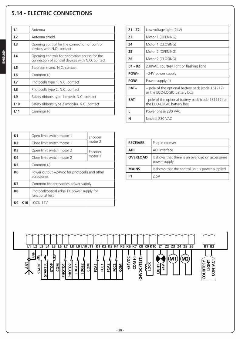
L1 Antenna
L2 Antenna shield
L3 Opening control for the connection of control devices with N.O. contact
L4 Opening controls for pedestrian access for the connection of control devices with N.O. contact
L5 Stop command. N.C. contact
L6 Common (-)
L7 Photocells type 1. N.C. contact
L8 Photocells type 2. N.C. contact
L9 Safety ribbons type 1 (fixed). N.C. contact
L10 Safety ribbons type 2 (mobile). N.C. contact
L11 Common (-)
Z1 - Z2 Low voltage light (24V)
Z3 Motor 1 (OPENING)
Z4 Motor 1 (CLOSING)
Z5 Motor 2 (OPENING)
Z6 Motor 2 (CLOSING)
B1 - B2 230VAC courtesy light or flashing light
POW+ +24V power supply
POW- Power supply (-)
BAT+ + pole of the optional battery pack (code 161212) or the ECO-LOGIC battery box
BAT- - pole of the optional battery pack (code 161212) or the ECO-LOGIC battery box
L Power phase 230 VAC
N Neutral 230 VAC
RECEIVER Plug in receiver
ADI ADI interface
OVERLOAD It shows that there is an overload on accessories power supply
MAINS It shows that the control unit is power supplied
F1 2,5A
K1 Open limit switch motor 1 Encoder motor 2K2 Close limit switch motor 1
K3 Open limit switch motor 2 Encoder motor 1K4 Close limit switch motor 2
K5 Common (-)
K6 Power output +24Vdc for photocells and other accessories
K7 Common for accessories power supply
K8 Photocell/optical edge TX power supply for functional test
K9 - K10 LOCK 12V
5.14 - ELECTRIC CONNECTIONS
EN
GLIS
H
- 31 -
F1
L N
LN
F1
MAINS
MAINS
CITY2+
CITY2+L
CITY2+CITY2+L
CITY2+BC
OVERLOAD
DOWN MENU UP
BAT-POW+
POW-
BA
T+
REC
EIV
ER
EN
GLI
SH
- 32 -
6 - CONTROL PANEL
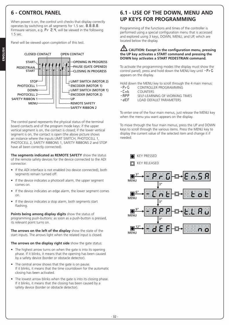
When power is on, the control unit checks that display correctly operates by switching on all segments for 1.5 sec. 8.8.8.8. Firmware version, e.g. Pr 2.4, will be viewed in the following 1.5 sec.
Panel will be viewed upon completion of this test.
The control panel represents the physical status of the terminal board contacts and of the program mode keys: if the upper vertical segment is on, the contact is closed; if the lower vertical segment is on, the contact is open (the above picture shows an instance where the inputs LIMIT SWITCH, PHOTOCELL 1, PHOTOCELL 2, SAFETY RIBBONS 1, SAFETY RIBBONS 2 and STOP have all been correctly connected).
The segments indicated as REMOTE SAFETY show the status of the remote safety devices for the device connected to the ADI connector.
• If the ADI interface is not enabled (no device connected), both segments remain turned off.
• If the device indicates a photocell alarm, the upper segment comes on.
• If the device indicates an edge alarm, the lower segment comes on.
• If the device indicates a stop alarm, both segments start flashing.
Points being among display digits show the status of programming push-buttons: as soon as a push-button is pressed, its relevant point turns on.
The arrows on the left of the display show the state of the start inputs. The arrows light when the related input is closed.
The arrows on the display right side show the gate status:
• The highest arrow turns on when the gate is into its opening phase. If it blinks, it means that the opening has been caused by a safety device (border or obstacle detector).
• The central arrow shows that the gate is on pause. If it blinks, it means that the time countdown for the automatic closing has been activated.
• The lowest arrow blinks when the gate is into its closing phase. If it blinks, it means that the closing has been caused by a safety device (border or obstacle detector).
6.1 - USE OF THE DOWN, MENU AND UP KEYS FOR PROGRAMMING
Programming of the functions and times of the controller is performed using a special configuration menu that is accessed and explored using 3 keys, DOWN, MENU, and UP, which are located below the display.
m CAUTION: Except in the configuration menu, pressing the UP key activates a START command and pressing the DOWN key activates a START PEDESTRIAN command.
To activate the programming modes (the display must show the control panel), press and hold down the MENU key until -PrG appears on the display.
Hold down the MENU key to scroll through the 4 main menus:-PrG CONTROLLER PROGRAMMING-Cnt COUNTERS-APP SELF-LEARNING OF WORKING TIMES-dEF LOAD DEFAULT PARAMETERS
To enter one of the four main menus, just release the MENU key when the menu you want appears on the display.
To move through the four main menus, press the UP and DOWN keys to scroll through the various items. Press the MENU key to display the current value of the selected item and change it if needed.
OPENING IN PROGRESS
OPEN CONTACTCLOSED CONTACT
START
PEDESTRIANSTART
PAUSE (GATE OPENED)CLOSING IN PROGRESS
STOPPHOTOCELL 1
DOWNPHOTOCELL 2
SAFETY RIBBON 1MENU
LIMIT SWITCH (MOTOR 2)ENCODER (MOTOR 1)LIMIT SWITCH (MOTOR 1)ENCODER (MOTOR 2)UPREMOTE SAFETYSAFETY RIBBON 2
MENU
3”
3”
3”
3”
MENU
6”
MENU
9”
MENU
12”
KEY PRESSED
KEY RELEASED
EN
GLIS
H
- 33 -
7 - QUICK CONFIGURATION
This paragraph concerns a quick procedure to set the control unit and set it at work immediately.
We recommend following these instructions, in order to check quickly the correct operation of control unit, motor and accessories, and then changing the configuration in case of any non-satisfactory parameter.
1. Call up the default configuration (chapter 8)
m CAUTION: If there is only one motor, set the open time, t.AP2, to zero in order to inform the controller that the parameters for motor 2 do not need to be considered.
2. Set items StoP - Fot1 - Fot2 - CoS1 - CoS2 according to the safety devices installed on the gate.
3. Start the self-learning cycle (chapter 11)
4. check that the automation work properly and if necessary modify the configuration of the desired parameters.
8 - LOADING OF DEFAULT PARAMETERS
If necessary, it is possible to restore all the parameters to their standard or default value (see table at the end)
m WARNING: This procedure causes the loss of all the customized parameters, therefore it has been put outside the configuration menu, to reduce the possibility of executing it by mistake.
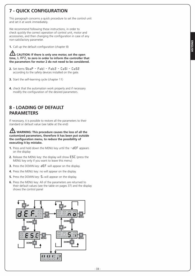
1. Press and hold down the MENU key until the -dEF appears on the display
2. Release the MENU key: the display will show ESC (press the MENU key only if you want to leave this menu)
3. Press the DOWN key: dEF will appear on the display.
4. Press the MENU key: no will appear on the display.
5. Press the DOWN key: Si will appear on the display.
6. Press the MENU key: All of the parameters are returned to their default values (see the table on pages 37) and the display shows the control panel
EN
GLI
SH
- 34 -
9 - SELF-LEARNING OF WORKING TIMES
This menu allows the automatic learning of the times necessary to open and close the gate.During this phase, the control unit memorizes also the forces necessary to open and close the gate: these values will be activated by using the obstacle sensor.The encoder positions are also saved, if enabled.
m CAUTION: Before continuing, make certain that the limit switch(es) and encoder(s) have been installed correctly. Limit switches and encoders, if installed, must be enabled using the specific menu.
m CAUTION: If the limit switches, the obstacle sensor or the encoder have NOT been enabled, make sure that when the procedure is started the leaves are completely closed.
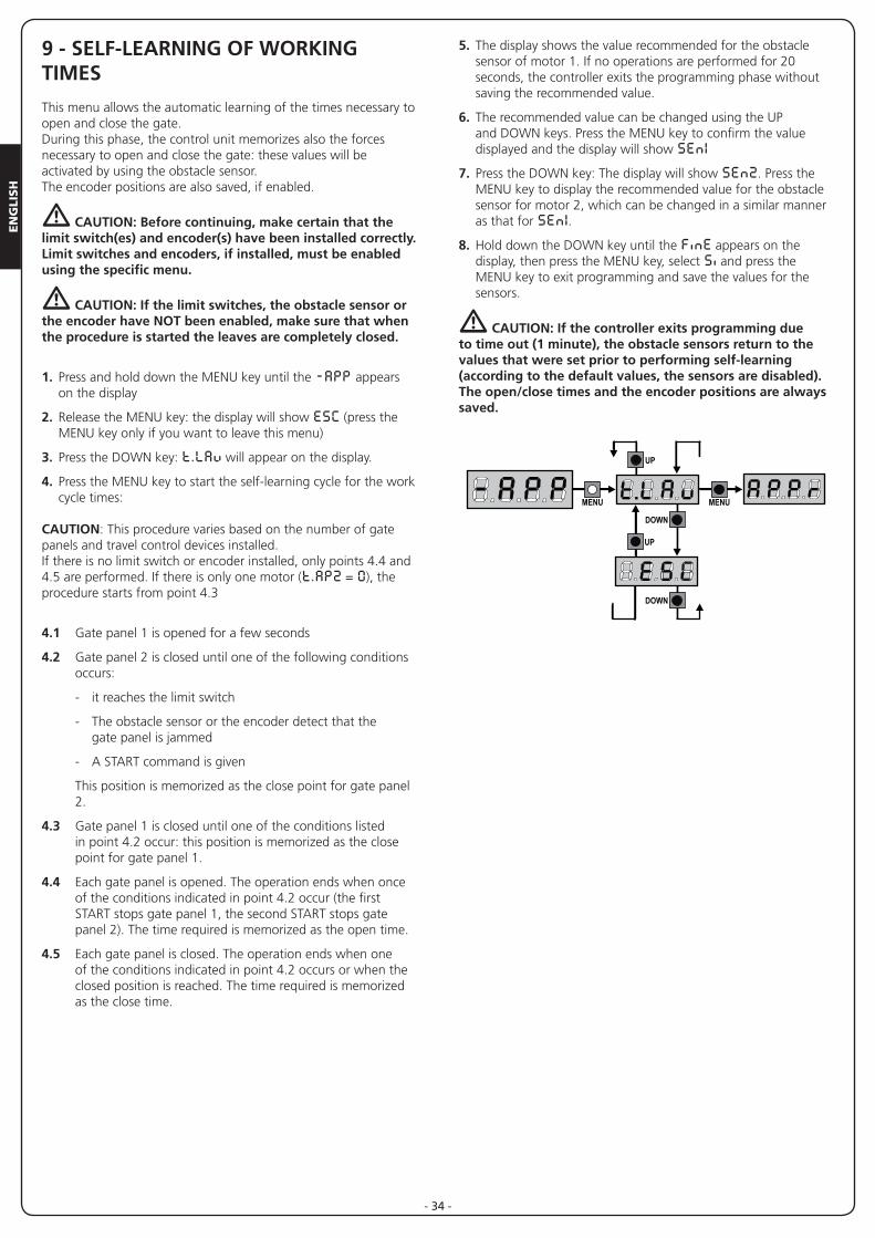
1. Press and hold down the MENU key until the -APP appears on the display
2. Release the MENU key: the display will show ESC (press the MENU key only if you want to leave this menu)
3. Press the DOWN key: t.LAv will appear on the display.
4. Press the MENU key to start the self-learning cycle for the work cycle times:
CAUTION: This procedure varies based on the number of gate panels and travel control devices installed. If there is no limit switch or encoder installed, only points 4.4 and 4.5 are performed. If there is only one motor (t.AP2 = 0), the procedure starts from point 4.3
4.1 Gate panel 1 is opened for a few seconds
4.2 Gate panel 2 is closed until one of the following conditions occurs:
- it reaches the limit switch
- The obstacle sensor or the encoder detect that the gate panel is jammed
- A START command is given
This position is memorized as the close point for gate panel 2.
4.3 Gate panel 1 is closed until one of the conditions listed in point 4.2 occur: this position is memorized as the close point for gate panel 1.
4.4 Each gate panel is opened. The operation ends when once of the conditions indicated in point 4.2 occur (the first START stops gate panel 1, the second START stops gate panel 2). The time required is memorized as the open time.
4.5 Each gate panel is closed. The operation ends when one of the conditions indicated in point 4.2 occurs or when the closed position is reached. The time required is memorized as the close time.
5. The display shows the value recommended for the obstacle sensor of motor 1. If no operations are performed for 20 seconds, the controller exits the programming phase without saving the recommended value.
6. The recommended value can be changed using the UP and DOWN keys. Press the MENU key to confirm the value displayed and the display will show SEn1
7. Press the DOWN key: The display will show SEn2. Press the MENU key to display the recommended value for the obstacle sensor for motor 2, which can be changed in a similar manner as that for SEn1.
8. Hold down the DOWN key until the FinE appears on the display, then press the MENU key, select Si and press the MENU key to exit programming and save the values for the sensors.
m CAUTION: If the controller exits programming due to time out (1 minute), the obstacle sensors return to the values that were set prior to performing self-learning (according to the default values, the sensors are disabled).The open/close times and the encoder positions are always saved.
EN
GLIS
H
- 35 -
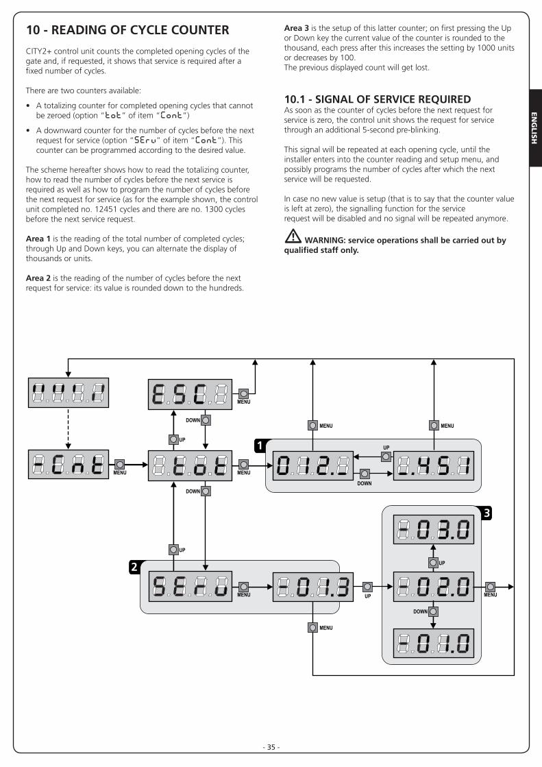
10 - READING OF CYCLE COUNTER
CITY2+ control unit counts the completed opening cycles of the gate and, if requested, it shows that service is required after a fixed number of cycles.
There are two counters available:
• A totalizing counter for completed opening cycles that cannot be zeroed (option “tot” of item “Cont”)
• A downward counter for the number of cycles before the next request for service (option “SErv” of item “Cont”). This counter can be programmed according to the desired value.
The scheme hereafter shows how to read the totalizing counter, how to read the number of cycles before the next service is required as well as how to program the number of cycles before the next request for service (as for the example shown, the control unit completed no. 12451 cycles and there are no. 1300 cycles before the next service request.
Area 1 is the reading of the total number of completed cycles; through Up and Down keys, you can alternate the display of thousands or units.
Area 2 is the reading of the number of cycles before the next request for service: its value is rounded down to the hundreds.
Area 3 is the setup of this latter counter; on first pressing the Up or Down key the current value of the counter is rounded to the thousand, each press after this increases the setting by 1000 units or decreases by 100.The previous displayed count will get lost.
10.1 - SIGNAL OF SERVICE REQUIRED As soon as the counter of cycles before the next request for service is zero, the control unit shows the request for service through an additional 5-second pre-blinking.
This signal will be repeated at each opening cycle, until the installer enters into the counter reading and setup menu, and possibly programs the number of cycles after which the next service will be requested.
In case no new value is setup (that is to say that the counter value is left at zero), the signalling function for the service request will be disabled and no signal will be repeated anymore.
m WARNING: service operations shall be carried out by qualified staff only.
3
1
2
EN
GLI
SH
- 36 -
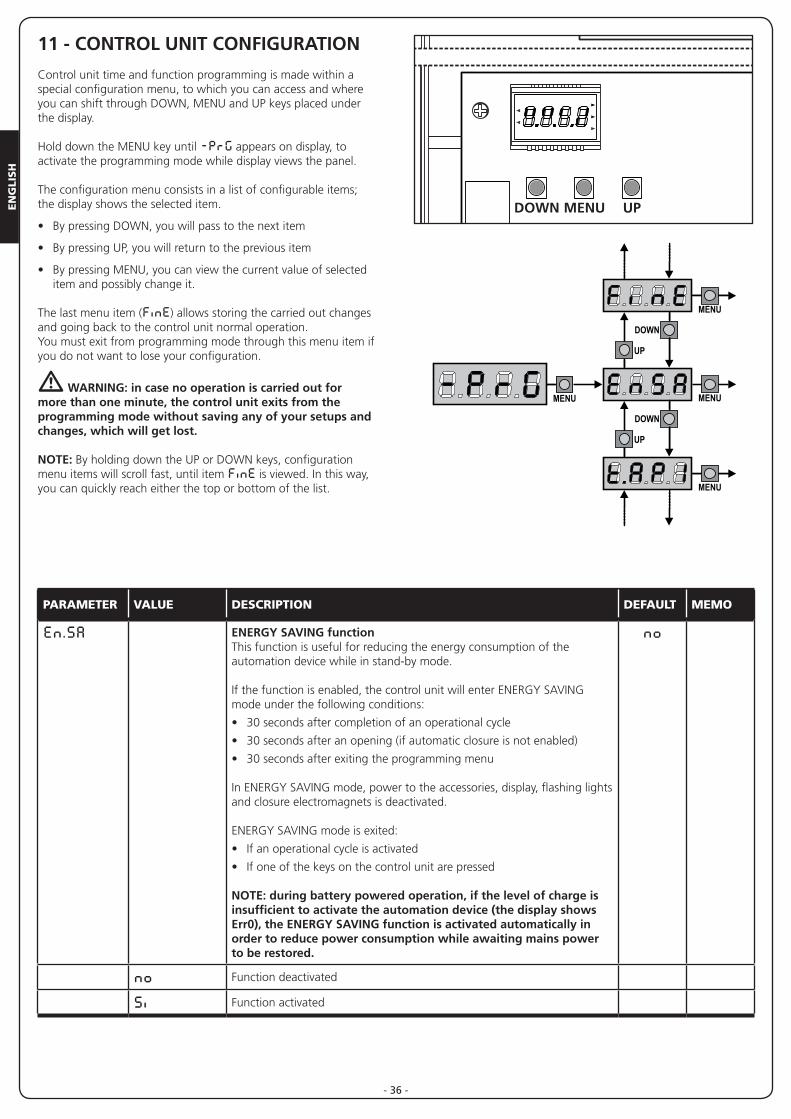
11 - CONTROL UNIT CONFIGURATION
Control unit time and function programming is made within a special configuration menu, to which you can access and where you can shift through DOWN, MENU and UP keys placed under the display.
Hold down the MENU key until -PrG appears on display, to activate the programming mode while display views the panel.
The configuration menu consists in a list of configurable items; the display shows the selected item.
• By pressing DOWN, you will pass to the next item
• By pressing UP, you will return to the previous item
• By pressing MENU, you can view the current value of selected item and possibly change it.
The last menu item (FinE) allows storing the carried out changes and going back to the control unit normal operation.You must exit from programming mode through this menu item if you do not want to lose your configuration.
m WARNING: in case no operation is carried out for more than one minute, the control unit exits from the programming mode without saving any of your setups and changes, which will get lost.
NOTE: By holding down the UP or DOWN keys, configuration menu items will scroll fast, until item FinE is viewed. In this way, you can quickly reach either the top or bottom of the list.
PARAMETER VALUE DESCRIPTION DEFAULT MEMO
En.SA ENERGY SAVING functionThis function is useful for reducing the energy consumption of the automation device while in stand-by mode.
If the function is enabled, the control unit will enter ENERGY SAVING mode under the following conditions:
• 30 seconds after completion of an operational cycle
• 30 seconds after an opening (if automatic closure is not enabled)
• 30 seconds after exiting the programming menu
In ENERGY SAVING mode, power to the accessories, display, flashing lights and closure electromagnets is deactivated.
ENERGY SAVING mode is exited:
• If an operational cycle is activated
• If one of the keys on the control unit are pressed
NOTE: during battery powered operation, if the level of charge is insufficient to activate the automation device (the display shows Err0), the ENERGY SAVING function is activated automatically in order to reduce power consumption while awaiting mains power to be restored.
no
no Function deactivated
Si Function activated
F1
L N
LN
F1
MAINS
MAINS
CITY2+
CITY2+L
CITY2+CITY2+L
CITY2+BC
OVERLOAD
DOWN MENU UP
BAT-POW+
POW-
BA
T+
REC
EIV
ER

EN
GLIS
H
- 37 -
PARAMETER VALUE DESCRIPTION DEFAULT MEMO
t.AP1 Leaf 1 opening time 22.5”0.0”-5’00 Adjustable time from 0 seconds to 5 minutes
t.AP2 Leaf 2 opening time 22.5”0.0”-5’00 Adjustable time from 0 seconds to 5 minutes.
WARNING: if motor 2 is not connected, this time must be set to zero
t.APP Partial opening time (pedestrian access) 6.0”0.0”-1’00 When the control unit receives a Start Pedestrian command, it will open
leaf 1 only, for a shorter time. Max allowed time to be setup is t.AP1
t.Ch1 Leaf 1 closing time 23.5”0.0”-5’00 Tempo regolabile da 0 secondi a 5 minuti
NOTA: Per evitare che l’anta non si chiuda completamente, è consigliabile impostare un tempo più lungo di quello di apertura t.AP1
t.Ch2 Tempo di chiusura anta 2 23.5”0.0”-5’00 Adjustable time from 0 seconds to 5 minutes.
NOTE: To avoid that the door does not close completely, we recommend to setup a longer time than t.AP2 opening time.
t.ChP Partial closing time (pedestrian access) 7.0”0.0” - 2’00 When the control unit receives a Start Pedestrian command, it will use this
time to close the gate. Max allowed time to be setup is t.Ch1.NOTE: To avoid that the door does not close completely, we recommend to setup a longer time than t.APP opening time
t.C2P Leaf 2 closing time during pedestrian cycle no0.5” - 5.0” During a partial opening cycle (pedestrian access) leaf 2 may move slightly
because of the wind or its own weight; in this case at closing time leaf 1 could hit leaf 2 and the gate would remain not perfectly closed.To avoid this, in the last seconds of the cycle a light closing force is applied to leaf 2 too.
no Function deactivated
r.AP Opening door delay 1.0”0.0” - 1’00 During the opening phase, leaf 1 must start moving before leaf 2, to avoid
that both doors may collide.Leaf 2 opening will be delayed for the setup time
r.Ch Closing door delay 3.0”0.0” - 1’00 During the closing phase, leaf 1 must start moving after leaf 2, to avoid
that both doors may collide.Leaf 1 closing will be delayed for the setup time
t.SEr Lock time 2.0”0.5”- 1’00 Before the opening phase begins, the control unit will energize the electric
lock in order to release it and enable the gate motion. t.SEr time will fix the energizing time.
m WARNING: in case the gate has no electric lock, set the value no
no Function deactivated
SEr.S Silent Locking Mode SiSi Function activated
no Function deactivated
EN
GLI
SH
- 38 -
PARAMETER VALUE DESCRIPTION DEFAULT MEMO
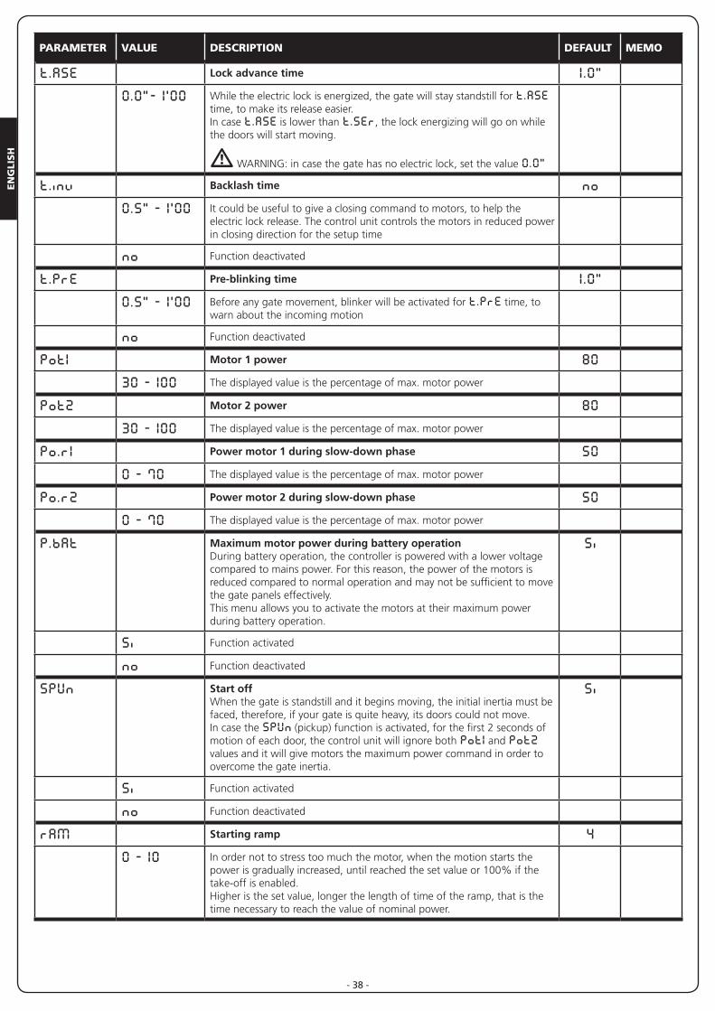
t.ASE Lock advance time 1.0”0.0”- 1’00 While the electric lock is energized, the gate will stay standstill for t.ASE
time, to make its release easier.In case t.ASE is lower than t.SEr, the lock energizing will go on while the doors will start moving.
m WARNING: in case the gate has no electric lock, set the value 0.0”
t.inv Backlash time no0.5” - 1’00 It could be useful to give a closing command to motors, to help the
electric lock release. The control unit controls the motors in reduced power in closing direction for the setup time
no Function deactivated
t.PrE Pre-blinking time 1.0”0.5” - 1’00 Before any gate movement, blinker will be activated for t.PrE time, to
warn about the incoming motion
no Function deactivated
Pot1 Motor 1 power 8030 - 100 The displayed value is the percentage of max. motor power
Pot2 Motor 2 power 8030 - 100 The displayed value is the percentage of max. motor power
Po.r1 Power motor 1 during slow-down phase 500 - 70 The displayed value is the percentage of max. motor power
Po.r2 Power motor 2 during slow-down phase 500 - 70 The displayed value is the percentage of max. motor power
P.bAt Maximum motor power during battery operationDuring battery operation, the controller is powered with a lower voltage compared to mains power. For this reason, the power of the motors is reduced compared to normal operation and may not be sufficient to move the gate panels effectively. This menu allows you to activate the motors at their maximum power during battery operation.
Si
Si Function activated
no Function deactivated
SPUn Start off When the gate is standstill and it begins moving, the initial inertia must be faced, therefore, if your gate is quite heavy, its doors could not move.In case the SPUn (pickup) function is activated, for the first 2 seconds of motion of each door, the control unit will ignore both Pot1 and Pot2 values and it will give motors the maximum power command in order to overcome the gate inertia.
Si
Si Function activated
no Function deactivated
rAM Starting ramp 40 - 10 In order not to stress too much the motor, when the motion starts the
power is gradually increased, until reached the set value or 100% if the take-off is enabled. Higher is the set value, longer the length of time of the ramp, that is the time necessary to reach the value of nominal power.
EN
GLIS
H
- 39 -
PARAMETER VALUE DESCRIPTION DEFAULT MEMO
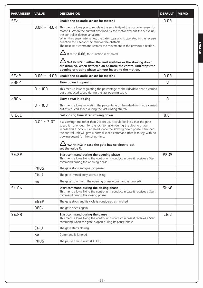
SEn1 Enable the obstacle sensor for motor 1 0.0A0.0A - 14.0A This menu allows you to regulate the sensitivity of the obstacle sensor for
motor 1. When the current absorbed by the motor exceeds the set value, the controller detects an alarm.When the sensor intervenes, the gate stops and is operated in the reverse direction for 3 seconds to remove the obstacle.The next start command restarts the movement in the previous direction.
m If set to 0.0A, this function is disabled
m WARNING: if either the limit switches or the slowing down are disabled, when detected an obstacle the control unit stops the opening or closing phase without inverting the motion.
SEn2 0.0A - 14.0A Enable the obstacle sensor for motor 1 0.0ArAAP Slow down in opening 0
0 - 100 This menu allows regulating the percentage of the ride/drive that is carried out at reduced speed during the last opening stretch
rACh Slow down in closing 00 - 100 This menu allows regulating the percentage of the ride/drive that is carried
out at reduced speed during the last closing stretch
t.CvE Fast closing time after slowing down 0.0”0.0” - 3.0” If a slowing time other than 0 is set up, it could be likely that the gate
speed is not enough for the lock to fasten during the closing phase. In case this function is enabled, once the slowing down phase is finished, the control unit will give a normal speed command (that is to say, with no slowing down) for the set up time.
m WARNING: in case the gate has no electric lock, set the value 0.
St.AP Start command during the opening phaseThis menu allows fixing the control unit conduct in case it receives a Start command during the opening phase
PAUS
PAUS The gate stops and goes to pause
ChiU The gate immediately starts closing
no The gate go on with the opening phase (command is ignored)
St.Ch Start command during the closing phaseThis menu allows fixing the control unit conduct in case it receives a Start command during the closing phase
StoP
StoP The gate stops and its cycle is considered as finished
APEr The gate opens again
St.PA Start command during the pauseThis menu allows fixing the control unit conduct in case it receives a Start command when the gate is open during its pause phase
ChiU
ChiU The gate starts closing
no Command is ignored
PAUS The pause time is reset (Ch.AU)
EN
GLI
SH
- 40 -
PARAMETER VALUE DESCRIPTION DEFAULT MEMO
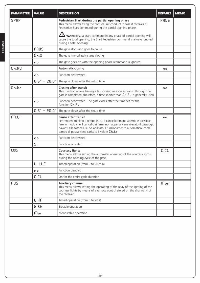
SPAP Pedestrian Start during the partial opening phaseThis menu allows fixing the control unit conduct in case it receives a Pedestrian Start command during the partial opening phase.
m WARNING: a Start command in any phase of partial opening will cause the total opening; the Start Pedestrian command is always ignored during a total opening.
PAUS
PAUS The gate stops and goes to pause
ChiU The gate immediately starts closing
no The gate goes on with the opening phase (command is ignored)
Ch.AU Automatic closing nono Function deactivated
0.5” - 20.0’ The gate closes after the setup time
Ch.tr Closing after transitThis function allows having a fast closing as soon as transit through the gate is completed, therefore, a time shorter than Ch.AU is generally used
no
no Function deactivated. The gate closes after the time set for thefunction Ch.AU
0.5” - 20.0’ The gate closes after the setup time
PA.tr Pause after transitPer rendere minimo il tempo in cui il cancello rimane aperto, è possibile fare in modo che il cancello si fermi non appena viene rilevato il passaggio davanti alle fotocellule. Se abilitato il funzionamento automatico, come tempo di pausa viene caricato il valore Ch.tr
no
no Function deactivated
Si Function activated
LUCi Courtesy lightsThis menu allows setting the automatic operating of the courtesy lights during the opening cycle of the gate.
CiCL
t .LUC Timed operation (from 0 to 20 min)
no Function disabled
CiCL On for the entire cycle duration
AUS Auxiliary channelThis menu allows setting the operating of the relay of the lighting of the courtesy lights by means of a remote control stored on the channel 4 of the receiver.
Mon
t iM Timed operation (from 0 to 20 s)
biSt Bistable operation
Mon Monostable operation
EN
GLIS
H
- 41 -
PARAMETER VALUE DESCRIPTION DEFAULT MEMO
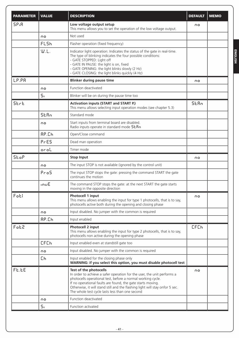
SPiA Low voltage output setupThis menu allows you to set the operation of the low voltage output.
no
no Not used
FLSh Flasher operation (fixed frequency)
W.L. Indicator light operation: Indicates the status of the gate in real-time. The type of blinking indicates the four possible conditions:- GATE STOPPED: Light off- GATE IN PAUSE: the light is on, fixed- GATE OPENING: the light blinks slowly (2 Hz)- GATE CLOSING: the light blinks quickly (4 Hz)
LP.PA Blinker during pause time nono Function deactivated
Si Blinker will be on during the pause time too
Strt Activation inputs (START and START P.)This menu allows selecting input operation modes (see chapter 5.3)
StAn
StAn Standard mode
no Start inputs from terminal board are disabled.Radio inputs operate in standard mode StAn
AP.Ch Open/Close command
PrES Dead man operation
oroL Timer mode
StoP Stop Input nono The input STOP is not available (ignored by the control unit)
ProS The input STOP stops the gate: pressing the command START the gate continues the motion
invE The command STOP stops the gate: at the next START the gate starts moving in the opposite direction
Fot1 Photocell 1 inputThis menu allows enabling the input for type 1 photocells, that is to say, photocells active both during the opening and closing phase
no
no Input disabled. No jumper with the common is required
AP.Ch Input enabled
Fot2 Photocell 2 inputThis menu allows enabling the input for type 2 photocells, that is to say, photocells non active during the opening phase
CFCh
CFCh Input enabled even at standstill gate too
no Input disabled. No jumper with the common is required
Ch Input enabled for the closing phase onlyWARNING: if you select this option, you must disable photocell test
Ft.tE Test of the photocellsIn order to achieve a safer operation for the user, the unit performs a photocells operational test, before a normal working cycle.If no operational faults are found, the gate starts moving. Otherwise, it will stand still and the flashing light will stay onfor 5 sec. The whole test cycle lasts less than one second
no
no Function deactivated
Si Function activated
EN
GLI
SH
- 42 -
PARAMETER VALUE DESCRIPTION DEFAULT MEMO
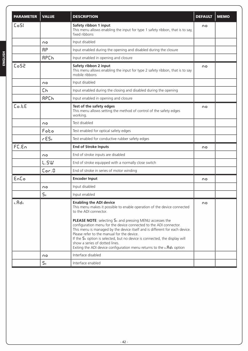
CoS1 Safety ribbon 1 inputThis menu allows enabling the input for type 1 safety ribbon, that is to say, fixed ribbons
no
no Input disabled
AP Input enabled during the opening and disabled during the closure
APCh Input enabled in opening and closure
CoS2 Safety ribbon 2 inputThis menu allows enabling the input for type 2 safety ribbon, that is to say mobile ribbons
no
no Input disabled
Ch Input enabled during the closing and disabled during the opening
APCh Input enabled in opening and closure
Co.tE Test of the safety edgesThis menu allows setting the method of control of the safety edges working.
no
no Test disabled
Foto Test enabled for optical safety edges
rESi Test enabled for conductive rubber safety edges
FC.En End of Stroke Inputs nono End of stroke inputs are disabled
L.SW End of stroke equipped with a normally close switch
Cor.0 End of stroke in series of motor winding
EnCo Encoder Input nono Input disabled
Si Input enabled
i.Adi Enabling the ADI deviceThis menu makes it possible to enable operation of the device connected to the ADI connector.
PLEASE NOTE: selecting Si and pressing MENU accesses the configuration menu for the device connected to the ADI connector.This menu is managed by the device itself and is different for each device. Please refer to the manual for the device.If the Si option is selected, but no device is connected, the display will show a series of dotted lines.Exiting the ADI device configuration menu returns to the i.Adi option
no
no Interface disabled
Si Interface enabled
EN
GLIS
H
- 43 -
PARAMETER VALUE DESCRIPTION DEFAULT MEMO
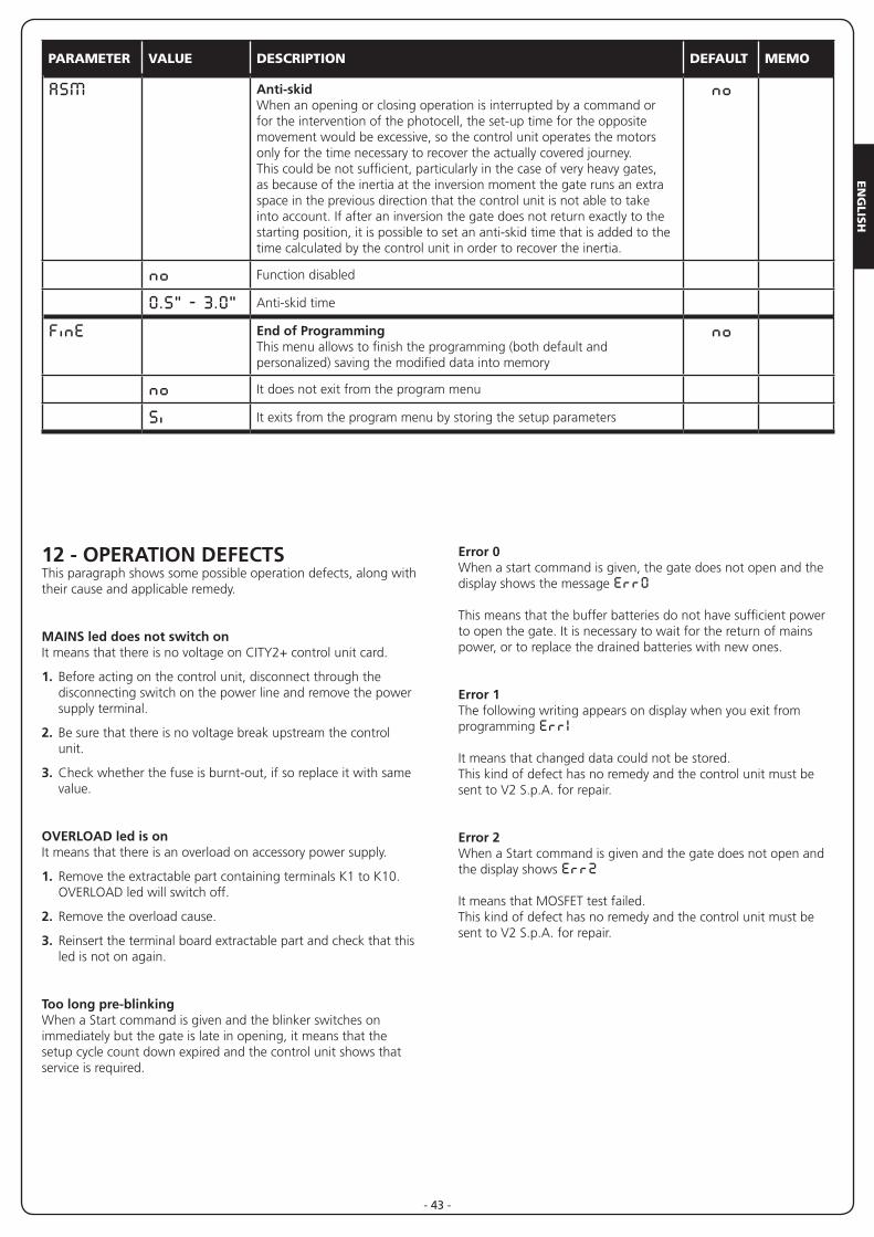
ASM Anti-skidWhen an opening or closing operation is interrupted by a command or for the intervention of the photocell, the set-up time for the opposite movement would be excessive, so the control unit operates the motors only for the time necessary to recover the actually covered journey. This could be not sufficient, particularly in the case of very heavy gates, as because of the inertia at the inversion moment the gate runs an extra space in the previous direction that the control unit is not able to take into account. If after an inversion the gate does not return exactly to the starting position, it is possible to set an anti-skid time that is added to the time calculated by the control unit in order to recover the inertia.
no
no Function disabled
0.5” - 3.0” Anti-skid time
FinE End of ProgrammingThis menu allows to finish the programming (both default and personalized) saving the modified data into memory
no
no It does not exit from the program menu
Si It exits from the program menu by storing the setup parameters
12 - OPERATION DEFECTSThis paragraph shows some possible operation defects, along with their cause and applicable remedy.
MAINS led does not switch on It means that there is no voltage on CITY2+ control unit card.
1. Before acting on the control unit, disconnect through the disconnecting switch on the power line and remove the power supply terminal.
2. Be sure that there is no voltage break upstream the control unit.
3. Check whether the fuse is burnt-out, if so replace it with same value.
OVERLOAD led is onIt means that there is an overload on accessory power supply.
1. Remove the extractable part containing terminals K1 to K10. OVERLOAD led will switch off.
2. Remove the overload cause.
3. Reinsert the terminal board extractable part and check that this led is not on again.
Too long pre-blinkingWhen a Start command is given and the blinker switches on immediately but the gate is late in opening, it means that the setup cycle count down expired and the control unit shows that service is required.
Error 0When a start command is given, the gate does not open and the display shows the message Err0
This means that the buffer batteries do not have sufficient power to open the gate. It is necessary to wait for the return of mains power, or to replace the drained batteries with new ones.
Error 1The following writing appears on display when you exit from programming Err1
It means that changed data could not be stored.This kind of defect has no remedy and the control unit must be sent to V2 S.p.A. for repair.
Error 2When a Start command is given and the gate does not open and the display shows Err2
It means that MOSFET test failed.This kind of defect has no remedy and the control unit must be sent to V2 S.p.A. for repair.
EN
GLI
SH
- 44 -
Error 3When a Start command is given and the gate does not open and the display shows Err3
It means that the photocell test failed.
1. Be sure that no obstacle interrupted the photocell beam when the Start command was given.
2. Be sure that photocells, as enabled by their relevant menus, have been installed actually.
3. If you have photocells 2, be sure that Fot2 menu item is on CF.Ch.
4. Be sure that photocells are powered and working; when you interrupt their beam, you should hear the relay tripping.
5. Ensure the photocells are connected correctly, as shown in the chapter 5.5
Error 4When a Start command is given and the gate does not open (or does a partial opening) and the display shows Err4
It means that the end of stroke is damaged or that the wiring that connects the sensor to the control unit is broken.
• Change the end of stroke sensor or the broken wiring. If the error persists send the control unit to V2 S.p.A. for repair.
• If limit switches have not been connected, check that the FC.En function is set to no.
Error 5Once given a start control, the gate does not open and the display shows Err5
It means that the test of the safety edges failed.Check that the menu of the test of safety edges (Co.tE) have been set correctly.Check that the safety edges enabled from the menu are installed.
Error 7The display shows Err7
This indicates an error in the encoders’ operation.There are three possible causes:
1. With the encoders connected, even if they are not enabled, for a few instants after movement of a gate panel. This means that the connection to the encoder for that gate panel is reversed. Exchange terminal K1 with K2, or K3 with K4
2. With the encoders enabled, once a START command is received: This means that the encoders have not been initialized. For the encoders to operate correctly, the self-learning procedure must be performed.
3. With the encoders enabled and initialized, a few seconds after movement begins: This means that an encoder is NOT correctly operating. Encoder malfunction or broken connection.
PLEASE NOTE: Check the connection is in line with the motor instructions
Error 8When executing a self-learning function the control is refused and the display shows Err8
It means that the setting of the control unit is not compatible with the requested function. In order to carry out self-learning, the Start inputs must be enabled in standard mode (Strt menu set to StAn) and the ADI interface must be disabled (i.Adi menu set to no). To survey the currents of the motor it is also necessary that the length of the opening and closure are at least of 7,5 second.
Error 9When you are trying to change the control unit setups and the the display shows Err9
It means that programming was locked by means of the programming lock key CL1+ (code 161213).To change the settings it is necessary to insert in the connector of the ADI interface the same key used to activate the programming lock, and unlock the device.
Error 10When a start command is given, the gate does not open and the display shows the message Er 10
This means that the ADI module function test failed.

V2 S.p.A.Corso Principi di Piemonte 65/67
12035 RACCONIGI CN (ITALY)Tel. +39 0172 812411 - Fax +39 0172 84050
www.v2home.com