Chaîne de transmission GSM Simulation système …matthieugautier.free.fr/media/TP_GSM_2010.pdf3.3...
44
Option Transversale Mobilité Mars 2010 1 Chaîne de transmission GSM Simulation système sous ADS et analyse vectorielle Virgile Garcia Matthieu Gautier
Transcript of Chaîne de transmission GSM Simulation système …matthieugautier.free.fr/media/TP_GSM_2010.pdf3.3...
Option Transversale Mobilité Mars 2010
1
Chaîne de transmission GSM
Simulation système sous ADS et analyse vectorielle
Virgile Garcia
Matthieu Gautier
Option Transversale Mobilité Mars 2010
2
SOMMAIRE
1 Prise en main du logiciel .............................................................................. 2
1.1 Les projets sous ADS................................................................................................ 3
1.2 Conception d’un système sous ADS........................................................................ 3
1.3 Simulation ................................................................................................................. 4
1.3.1 Les contrôleurs de simulation ............................................................................ 6
1.3.2 Harmonic Balance .............................................................................................. 7
1.3.3 Circuit Enveloppe............................................................................................... 8
1.3.4 DATA FLOW simulation controller ................................................................ 11
1.4 Analyse des résultats .............................................................................................. 11
2 Application : génération d’un signal RF modulé ....................................13
2.1 Créer la schématique.............................................................................................. 13
2.2 Etude de la source temporelle ............................................................................... 15
2.3 Etude de la source fréquentielle............................................................................ 16
2.4 Etude du signal modulé.......................................................................................... 17
3 Etude de signaux GSM...............................................................................20
3.1 La modulation GMSK ........................................................................................... 21
3.2 Etude des effets de la propagation du signal avec l’analyseur de spectre
vectoriel (en simulation)..................................................................................................... 21
3.3 Analyse d’une trame TDMA ................................................................................. 26
3.4 Analyse d’un signal GSM pour une liaison montante et descendante. ............. 34
1 Prise en main du logiciel
Cette partie est une présentation concise de l’utilisation du logiciel et de ses possibilités.
Option Transversale Mobilité Mars 2010
3
1.1 Les projets sous ADS
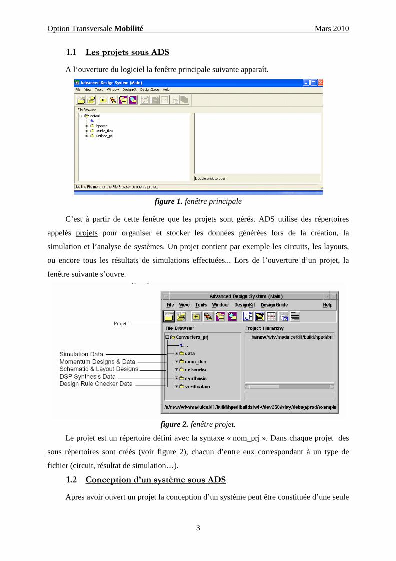
A l’ouverture du logiciel la fenêtre principale suivante apparaît.
figure 1. fenêtre principale
C’est à partir de cette fenêtre que les projets sont gérés. ADS utilise des répertoires
appelés projets pour organiser et stocker les données générées lors de la création, la
simulation et l’analyse de systèmes. Un projet contient par exemple les circuits, les layouts,
ou encore tous les résultats de simulations effectuées... Lors de l’ouverture d’un projet, la
fenêtre suivante s’ouvre.
figure 2. fenêtre projet.
Le projet est un répertoire défini avec la syntaxe « nom_prj ». Dans chaque projet des
sous répertoires sont créés (voir figure 2), chacun d’entre eux correspondant à un type de
fichier (circuit, résultat de simulation…).
1.2 Conception d’un système sous ADS
Apres avoir ouvert un projet la conception d’un système peut être constituée d’une seule
Projet
Option Transversale Mobilité Mars 2010
4
structure ou bien dans le cas de système complexe, de plusieurs systèmes incorporés comme
un sous réseau dans un fichier. Pour créer un système, il faut ouvrir une fenêtre appelée
« schématique ». Pour cela, il suffit de cliquer sur l’icône correspondant (« New Schematic
Window ») de la fenêtre principale, ou bien sur l’onglet « window/New schematic » de cette
même fenêtre. Il est aussi possible de créer un nouveau design dans l’onglet file de la fenêtre
principale (« File/New Design »). Dans ce dernier cas, à l’ouverture de la fenêtre, deux types
de « schématiques » sont possibles : schematic RF/analog Design (traitement analogique) ou
schematic DSP Design (analyse numérique). Dans cette fenêtre il est possible de :
� Créer et modifier des circuits et des « layout »
� Ajouter des variables et des équations
� Placer et configurer des composants, des contrôleurs de simulations
� Générer un layout à partir d’un système et inversement
� Ajouter des commentaires
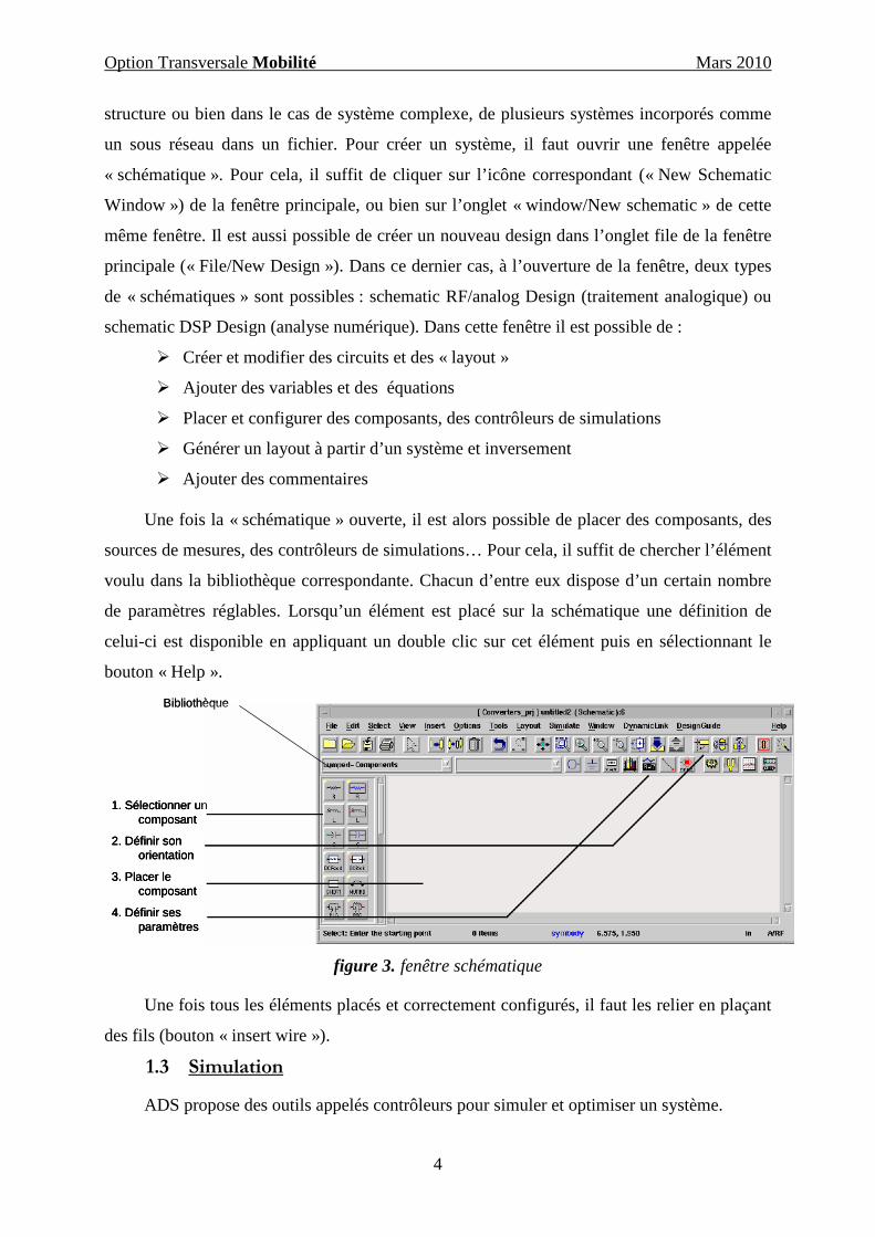
Une fois la « schématique » ouverte, il est alors possible de placer des composants, des
sources de mesures, des contrôleurs de simulations… Pour cela, il suffit de chercher l’élément
voulu dans la bibliothèque correspondante. Chacun d’entre eux dispose d’un certain nombre
de paramètres réglables. Lorsqu’un élément est placé sur la schématique une définition de
celui-ci est disponible en appliquant un double clic sur cet élément puis en sélectionnant le
bouton « Help ».
1. Sélectionner un composant
2. Définir son orientation
3. Placer le composant
4. Définir ses paramètres
Bibliothèque
1. Sélectionner un composant
2. Définir son orientation
3. Placer le composant
4. Définir ses paramètres
1. Sélectionner un composant
2. Définir son orientation
3. Placer le composant
4. Définir ses paramètres
Bibliothèque
figure 3. fenêtre schématique
Une fois tous les éléments placés et correctement configurés, il faut les relier en plaçant
des fils (bouton « insert wire »).
1.3 Simulation
ADS propose des outils appelés contrôleurs pour simuler et optimiser un système.
Option Transversale Mobilité Mars 2010
5
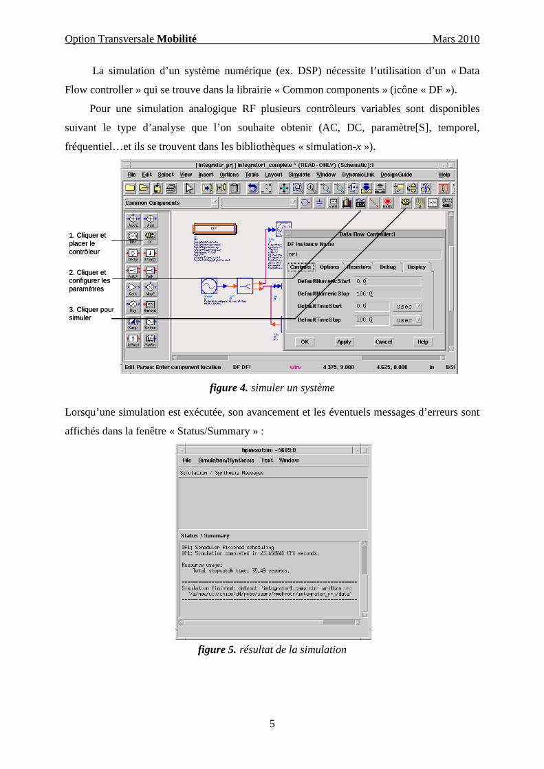
La simulation d’un système numérique (ex. DSP) nécessite l’utilisation d’un « Data
Flow controller » qui se trouve dans la librairie « Common components » (icône « DF »).
Pour une simulation analogique RF plusieurs contrôleurs variables sont disponibles
suivant le type d’analyse que l’on souhaite obtenir (AC, DC, paramètre[S], temporel,
fréquentiel…et ils se trouvent dans les bibliothèques « simulation-x »).
1. Cliquer et placer le contrôleur
2. Cliquer et configurer les paramètres
3. Cliquer pour simuler
1. Cliquer et placer le contrôleur
2. Cliquer et configurer les paramètres
3. Cliquer pour simuler
figure 4. simuler un système
Lorsqu’une simulation est exécutée, son avancement et les éventuels messages d’erreurs sont
affichés dans la fenêtre « Status/Summary » :
figure 5. résultat de la simulation

Option Transversale Mobilité Mars 2010
6
1.3.1 Les contrôleurs de simulation
Un ou plusieurs contrôleurs peuvent être placés dans un « design » suivant le type de
simulation recherché. Ces éléments permettent de sélectionner la plage temporelle ou
fréquentielle de simulation ainsi que le type de résultats obtenus.
La liste des principaux contrôleurs disponibles est décrite dans le tableau suivant :
Type de contrôleur description Utilisation typique
Data Flow simulation
controller
Analyse de signaux numériques et
temporels lors d’une simulation DSP
utilisant le simulateur ptolemy
tous les systèmes type
DSP
DC simulation
controller
Il exécute un contrôle et une analyse du
comportement en régime continu
Tous les systèmes
RF/analog
AC simulation
controller
Permet d’obtenir la fonction de transfert
en petit signal tel que le gain ou le bruit en
tension et courant
filtres, amplificateurs
S parameter simulation
controller
Fournit les paramètres S linéaires,
paramètres de bruit linéaires,
transimpédance et transmittance
filtres,
oscillateurs,
amplificateurs
Harmonic balance
simulation controller
Utilise des techniques non linéaires de
balance harmonique pour trouver un état
stable du système dans le domaine
fréquentiel
mélangeur,
oscillateur,
récepteur,
ampli. de puissance
Circuit enveloppe
simulation controller
Utilise une combinaison des techniques
d’analyse dans le domaine temporel et
fréquentiel pour rapporter une analyse
rapide et complète d’un signal complexe,
tel qu’un signal RF avec une modulation
complexe
mélangeur, oscillateur,
Ampli. de puissance,
récepteur,
LSSP simulation
controller
Etend l’analyse en paramètres S pour de
forts signaux pour visualiser le
comportement non linéaire
amplificateur
de puissance

Option Transversale Mobilité Mars 2010
7
Transient/
Simulation controller
Résout un système non linéaire dans le
domaine temporel utilisant des modèles
simplifiés tenant compte de la dépendance
en fréquence du comportement des
éléments distribués
mélangeur,
ampli de puissance,
« switch »
Au cours du TP vous utiliserez surtout les contrôleurs « DataFlow », « Harmonic
Balance » et « circuit enveloppe ».
1.3.2 Harmonic Balance
Le contrôleur de simulation « Harmonic Balance » (HB) est un outil d’analyse dans le
domaine fréquentiel pour étudier les distorsions dans les circuits et systèmes non linéaires.
Pour une étude HB, il faut impérativement utiliser des sources contrôlées en fréquence qui se
trouvent dans la bibliothèque « frequency domain source ».
figure 6. contrôleur HB
Il faut définir les fréquences que l’on souhaite étudier et l’ordre des harmoniques pris en
compte. Il permet de calculer les composantes fréquentielles contenues dans les signaux en
tension et courant du circuit, d’évaluer la distorsion due aux harmoniques et à l’inter
modulation et les performances en termes de bruit non linéaire.
« Harmonic Balance » présente de nombreux avantages par rapport à une analyse avec
le contrôleur « transient ». En effet, HB capture directement la réponse spectrale stationnaire
alors que la méthode traditionnelle en temporel nécessite le besoin d’intégrer beaucoup de
périodes de la sinusoïde à la fréquence la plus basse pour atteindre l’état stable. Il résout assez
rapidement les problèmes aux hautes fréquences alors que « transient » ne peut pas les traiter
ou alors avec un coût temporel excessif. Enfin, il est plus approprié pour étudier les
phénomènes hautes fréquences où les modèles sont élaborés « pour et dans » le domaine
fréquentiel.

Option Transversale Mobilité Mars 2010
8
1.3.3 Circuit Enveloppe
Ce contrôleur est le plus approprié à une analyse rapide et complète d’un signal
complexe tel qu’un signal numérique modulé. Il combine les caractéristiques dans les
domaines fréquentiels et temporels en permettant aux ondes en entrée d’être représentées
comme la somme d’une porteuse RF décrite et simulée dans le domaine fréquentiel et une
enveloppe de modulation représentée quant à elle dans le domaine temporel.
figure 7. contrôleur simulation enveloppe.
Le processus d’analyse avec le contrôleur d’enveloppe est le suivant :
1) Transformation du signal d’entrée
figure 8. définition du signal d’entrée
Chaque signal modulé peut être représenté comme une porteuse modulée par une
enveloppe, A(t)*exp j[f(t)]. L’amplitude et la phase de l’enveloppe échantillonnée sont
utilisées comme signal d’entrée pour l’analyse harmonique balance.
Option Transversale Mobilité Mars 2010
9
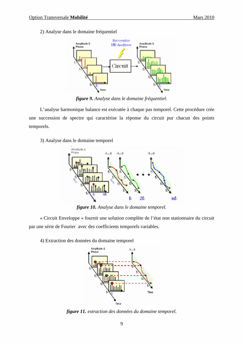
2) Analyse dans le domaine fréquentiel
figure 9. Analyse dans le domaine fréquentiel.
L’analyse harmonique balance est exécutée à chaque pas temporel. Cette procédure crée
une succession de spectre qui caractérise la réponse du circuit pur chacun des points
temporels.
3) Analyse dans le domaine temporel
figure 10. Analyse dans le domaine temporel.
« Circuit Enveloppe » fournit une solution complète de l’état non stationnaire du circuit
par une série de Fourier avec des coefficients temporels variables.
4) Extraction des données du domaine temporel
figure 11. extraction des données du domaine temporel.

Option Transversale Mobilité Mars 2010
10
En sélectionnant l’harmonique désirée dans le spectre (fc dans l’exemple), il est possible
d’analyser :
L’amplitude en fonction du temps (démarrage d’un oscillateur…)
La phase en fonction du temps (fréquence instantanée d’un VCO df/dt…)
L’amplitude et la phase en fonction du temps (constellation, BER,EVM…)
5) Extraction des données du domaine fréquentiel
figure 12. extraction des données dans le domaine fréquentiel.
En appliquant une transformée de Fourier du spectre temporel sélectionné, il est possible
d’analyser :
-Le rapport de puissance du canal adjacent (ACPR)
-Le rapport de la puissance de bruit (NPR)
-L’ordre supérieur d’inter modulation
Les étapes de la simulation sont les suivantes:
-Définir la modulation du signal en bande de base
-Prédéfinir les sources
-Equations
-Les données I et Q en fonction du temps pour les simulations DSP
-Définir la fréquence de la porteuse RF, le pas temporel et la durée de la simulation
-Calculer les coefficients de Fourier
-Post-process et visualisation des résultats

Option Transversale Mobilité Mars 2010
11
Ou encore :
-Définir le signal d’entrée avec la modulation d’amplitude de phase ou de fréquence, I
et Q…
-Définir le pas temporel
-Simuler et calculer les coefficients de Fourier temporel
-Calculer les transformées de Fourier et visualiser le spectre en fréquence du signal
(module, phase).
1.3.4 DATA FLOW simulation controller
Ce contrôleur est utilisé pour contrôler le flux des signaux numériques et temporels pour
toutes les simulations de systèmes numériques avec ADS. Il permet de contrôler la plage
temporelle et le nombre de symboles simulés.
figure 13. contrôleur de simulation Data Flow
1.4 Analyse des résultats
Les résultats des simulations effectuées sont enregistrés dans le fichier « dataset » qui
est stocké dans le répertoire data du projet. L’icône « data display » permet d’accéder à la
fenêtre d’analyse des résultats. Dans cette fenêtre, il est possible de tracer des graphes,
d’écrire des équations pour effectuer des calculs, utiliser des marqueurs et illustrer les
analyses avec des annotations.
La procédure à suivre pour ouvrir une fenêtre d’analyse est représentée sur la figure 14
(voir page suivante).

Option Transversale Mobilité Mars 2010
12
1. Cliquer pour ouvrir la fenêtre data display
2. Cliquer et choisir le type de graphique
3. Sélectionner les données à tracer et les options du traceur
1. Cliquer pour ouvrir la fenêtre data display
2. Cliquer et choisir le type de graphique
3. Sélectionner les données à tracer et les options du traceur
figure 14. ouverture fenêtre d’analyse.

Option Transversale Mobilité Mars 2010
13
2 Application : génération d’un signal RF modulé
Le but de cette application est de vous familiariser et de prendre en main le logiciel de
CAO en concevant et en analysant un système simple. Pour cela il vous sera demandé de
générer un signal RF avec une modulation pi/4DQPSK. Le système sera composé d’une
source en fréquence, d’une source de donnée binaire pseudo aléatoire, d’un modulateur et
enfin d’un filtre. L’architecture du système est représentée sur la figure 15.
figure 15. Topologie du système
2.1 Créer la schématique
Dans un premier temps, créez un nouveau projet que vous nommez TP_source_mod et
ouvrez la fenêtre schématique.
Quand vous placez un élément, la signification de ses différents paramètres est
disponible en cliquant sur l’icône help de sa fenêtre de paramétrage. Vous accédez à cette
fenêtre en appliquant un double clic sur l’élément. A chaque fois que vous changez un
paramètre, cliquez sur l’icône « apply » pour le valider. Pour déplacer la zone de texte
décrivant les paramètres d’un élément appuyer sur F5 et sélectionner l’élément.
Placez les différents éléments nécessaires et pour chacun d’entre eux examinez en
détails leurs caractéristiques.
Dans la bibliothèque « source-freq domain » sélectionnez la source P_1tone et placez
cette source sur la schématique. Réglez les paramètres de la puissance et de la fréquence :

Option Transversale Mobilité Mars 2010
14
P_1TonePORT1
Freq=RFfreqP=polar(dbmtow(PRF),0)Z=50 OhmNum=1
P=polar(dbmtow(PRF),0), la fonction dbmtow convertit la puissance de dBm en watt.
Les valeurs numériques de la puissance et la fréquence seront ensuite définies dans la
déclaration des variables.
Vous trouverez la source de donnée binaire pseudo aléatoire dans la bibliothèque
« source-time domain » (DT LFSR). Réglez les paramètres suivants la configuration
suivante :
VtLFSR_DTSRC2
Rout=1 OhmSeed=bin("10101010101010101")Taps=bin("10000000000000100")Delay=0 nsecRate=2*sym_rateVhigh=1 VVlow=-1 V
DT
Cette source génère une séquence aléatoire de bits qui se répète après 8191 bits.
Le modulateur au format pi/4DQPsk se trouve dans la bibliothèque « system
mod/demod ».
PI4DQPSK_ModTunedMOD1
Delay=0 nsecSymbolRate=sym_rateRout=50 OhmFnom=RFfreq
Le filtre se trouve dans la bibliothèque « filter band pass » :
BPF_RaisedCosBPF1
SincE=noDutyCycle=100Exponent=0.5DelaySymbols=Filt_delay_symsSymbolRate=sym_rateFcenter=RFfreqAlpha=0.5
Apres avoir placé et paramétré les éléments, il faut alors déclarer les variables utilisées.
Pour cela cliquez sur l’icône « VAR » de la fenêtre « schématique » et ajoutez les variables
Option Transversale Mobilité Mars 2010
15
suivantes ci-après.
VARVAR1
sym_rate=24.3 kHzFilt_delay_syms=15RFfreq=800 MHzPRF=10 _dBmtstep=1/(sym_rate*sam_per_sym)sam_per_sym=10numpts=256*10
EqnVar
Cela correspond à un débit de symboles de 24.3 kHz, le nombre d’échantillon temporel
par symbole est 10. Le nombre de points simulés est représenté par numpts et le nombre de
symbole simulés=numpts/sam_per_sym.
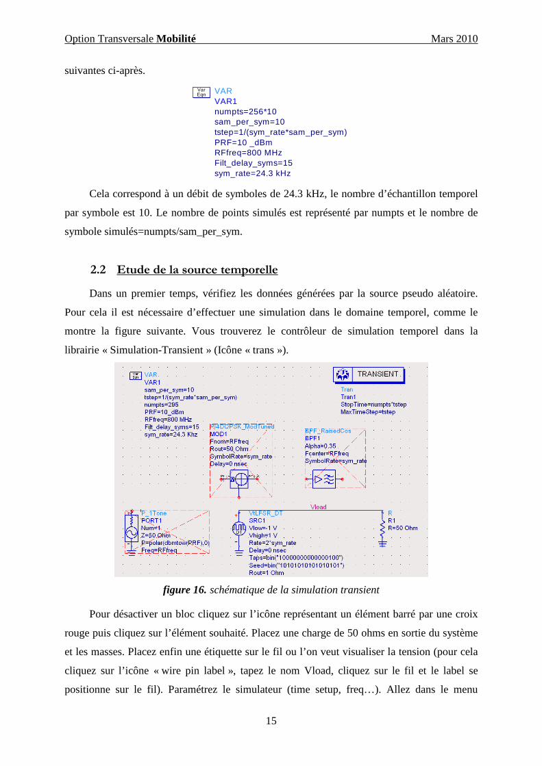
2.2 Etude de la source temporelle
Dans un premier temps, vérifiez les données générées par la source pseudo aléatoire.
Pour cela il est nécessaire d’effectuer une simulation dans le domaine temporel, comme le
montre la figure suivante. Vous trouverez le contrôleur de simulation temporel dans la
librairie « Simulation-Transient » (Icône « trans »).
figure 16. schématique de la simulation transient
Pour désactiver un bloc cliquez sur l’icône représentant un élément barré par une croix
rouge puis cliquez sur l’élément souhaité. Placez une charge de 50 ohms en sortie du système
et les masses. Placez enfin une étiquette sur le fil ou l’on veut visualiser la tension (pour cela
cliquez sur l’icône « wire pin label », tapez le nom Vload, cliquez sur le fil et le label se
positionne sur le fil). Paramétrez le simulateur (time setup, freq…). Allez dans le menu
Option Transversale Mobilité Mars 2010
16
Output et cliquez sur add/remove, sélectionnez Vload et Add, cela permettra de visualiser la
tension Vload.
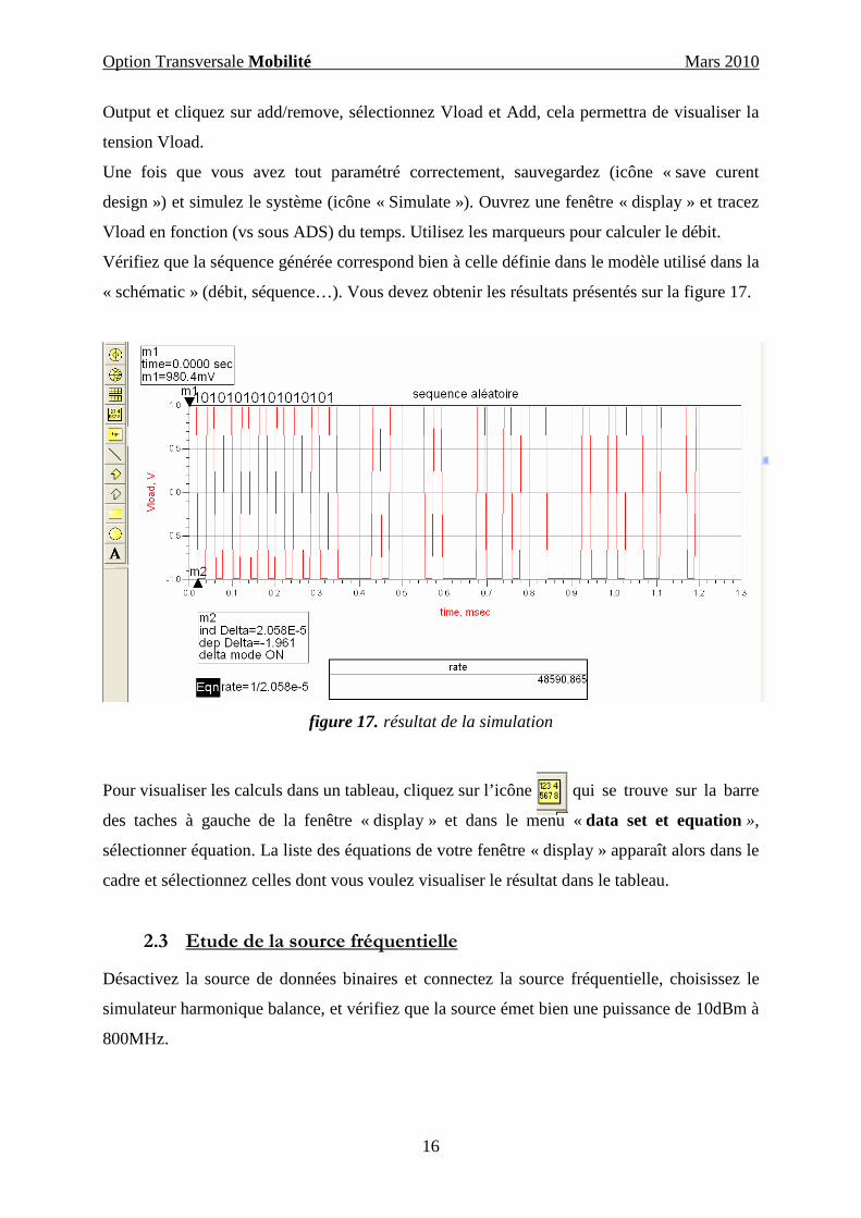
Une fois que vous avez tout paramétré correctement, sauvegardez (icône « save curent
design ») et simulez le système (icône « Simulate »). Ouvrez une fenêtre « display » et tracez
Vload en fonction (vs sous ADS) du temps. Utilisez les marqueurs pour calculer le débit.
Vérifiez que la séquence générée correspond bien à celle définie dans le modèle utilisé dans la
« schématic » (débit, séquence…). Vous devez obtenir les résultats présentés sur la figure 17.
figure 17. résultat de la simulation
Pour visualiser les calculs dans un tableau, cliquez sur l’icône qui se trouve sur la barre
des taches à gauche de la fenêtre « display » et dans le menu « data set et equation »,
sélectionner équation. La liste des équations de votre fenêtre « display » apparaît alors dans le
cadre et sélectionnez celles dont vous voulez visualiser le résultat dans le tableau.
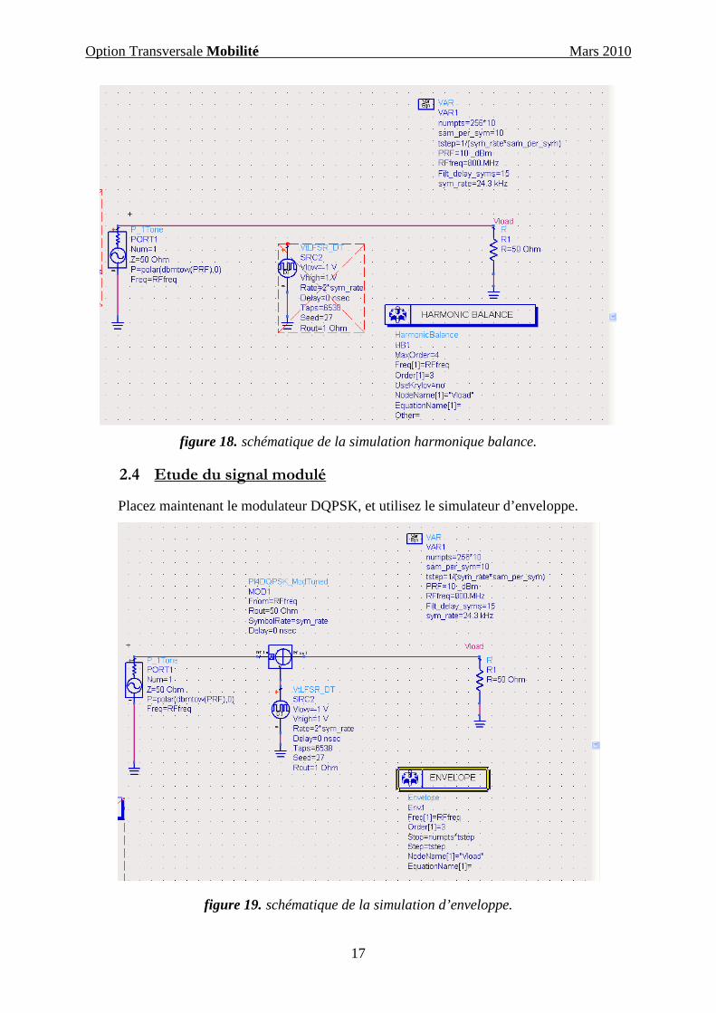
2.3 Etude de la source fréquentielle
Désactivez la source de données binaires et connectez la source fréquentielle, choisissez le
simulateur harmonique balance, et vérifiez que la source émet bien une puissance de 10dBm à
800MHz.
Option Transversale Mobilité Mars 2010
17
figure 18. schématique de la simulation harmonique balance.
2.4 Etude du signal modulé
Placez maintenant le modulateur DQPSK, et utilisez le simulateur d’enveloppe.
figure 19. schématique de la simulation d’enveloppe.
Option Transversale Mobilité Mars 2010
18
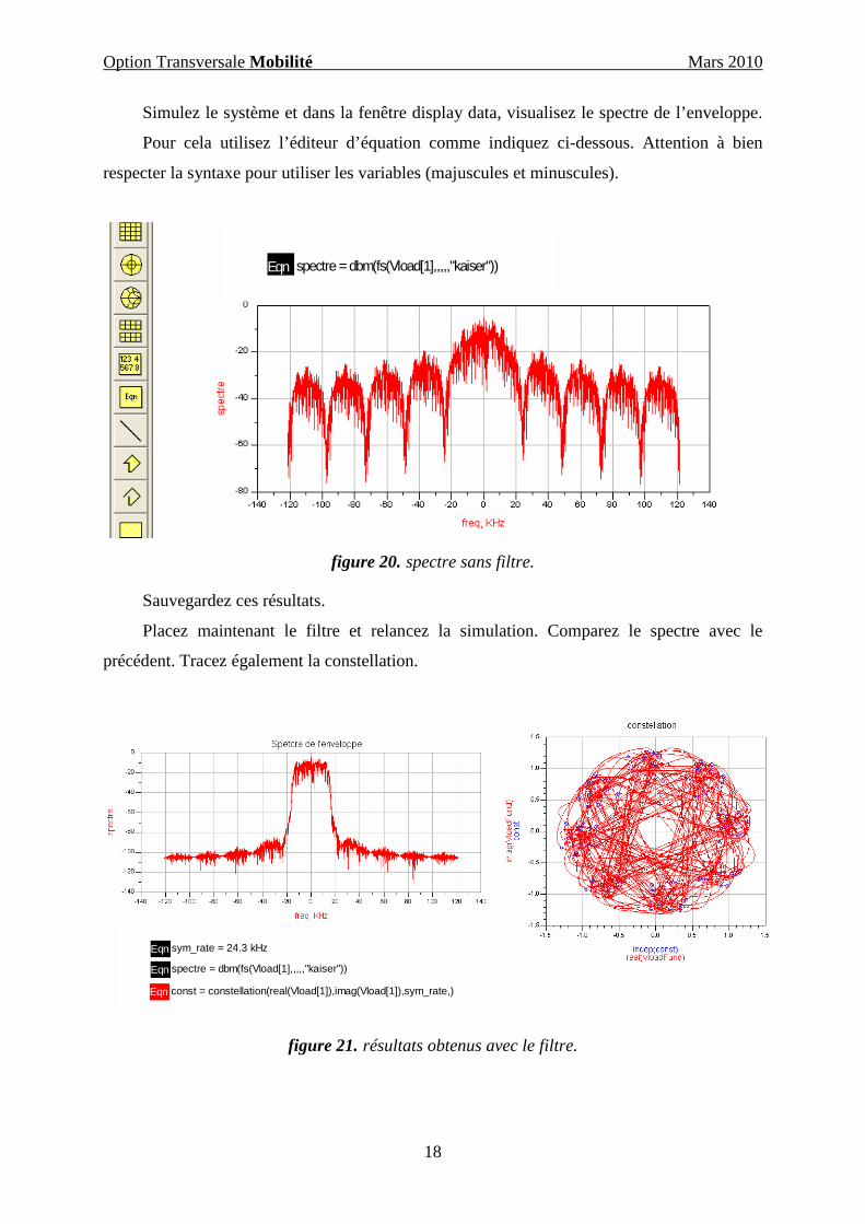
Simulez le système et dans la fenêtre display data, visualisez le spectre de l’enveloppe.
Pour cela utilisez l’éditeur d’équation comme indiquez ci-dessous. Attention à bien
respecter la syntaxe pour utiliser les variables (majuscules et minuscules).
Eqn spectre=dbm(fs(Vload[1],,,,,"kaiser"))Eqn spectre=dbm(fs(Vload[1],,,,,"kaiser"))Eqn spectre = dbm(fs(Vload[1],,,,,"kaiser"))Eqn spectre=dbm(fs(Vload[1],,,,,"kaiser"))Eqn spectre=dbm(fs(Vload[1],,,,,"kaiser"))Eqn spectre = dbm(fs(Vload[1],,,,,"kaiser"))
figure 20. spectre sans filtre.
Sauvegardez ces résultats.
Placez maintenant le filtre et relancez la simulation. Comparez le spectre avec le
précédent. Tracez également la constellation.
Eqn sym_rate = 24.3 kHz
Eqn spectre = dbm(fs(Vload[1],,,,,"kaiser"))
Eqn const = constellation(real(Vload[1]),imag(Vload[1]),sym_rate,)
figure 21. résultats obtenus avec le filtre.

Option Transversale Mobilité Mars 2010
19
Calculez la puissance sur une plage de 40 KHz puis la DSP, pour cela utilisez la
fonction chanel_power_vr (une définition des fonctions est disponible dans la fenêtre de
l’éditeur d’équation, en cliquant sur « functions help »).
Attention la fonction chanel_power_vr ne donne pas directement la DSP !
Commentez et concluez.
Option Transversale Mobilité Mars 2010
20
3 Etude de signaux GSM
Dans cette partie, vous analysez la transmission de signaux GSM à l’aide d’exemples
déjà modélisés sous ADS. Certaines questions vous guideront dans cette partie mais à vous de
faire preuve d’initiative et d’analyser en détails ces exemples en apportant les modifications
que vous jugerez utiles. Dans un premier temps vous étudierez la modulation GMSK puis
vous regarderez plus précisément les canaux de transmission et l’analyse en lien montant et
descendant.
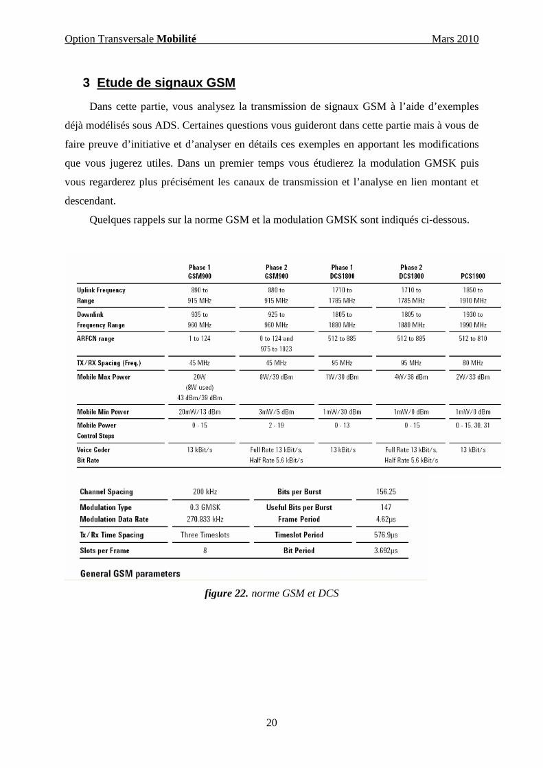
Quelques rappels sur la norme GSM et la modulation GMSK sont indiqués ci-dessous.
figure 22. norme GSM et DCS
Option Transversale Mobilité Mars 2010
21
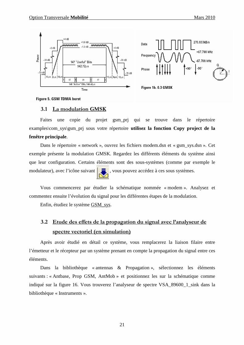
3.1 La modulation GMSK
Faites une copie du projet gsm_prj qui se trouve dans le répertoire
examples\com_sys\gsm_prj sous votre répertoire utilisez la fonction Copy project de la
fenêtre principale.
Dans le répertoire « network », ouvrez les fichiers modem.dsn et « gsm_sys.dsn ». Cet
exemple présente la modulation GMSK. Regardez les différents éléments du système ainsi
que leur configuration. Certains éléments sont des sous-systèmes (comme par exemple le
modulateur), avec l’icône suivant , vous pouvez accédez à ces sous systèmes.
Vous commencerez par étudier la schématique nommée « modem ». Analysez et
commentez ensuite l’évolution du signal pour les différentes étapes de la modulation.
Enfin, étudiez le système GSM_sys.
3.2 Etude des effets de la propagation du signal avec l’analyseur de
spectre vectoriel (en simulation)
Après avoir étudié en détail ce système, vous remplacerez la liaison filaire entre
l’émetteur et le récepteur par un système prenant en compte la propagation du signal entre ces
éléments.
Dans la bibliothèque « antennas & Propagation », sélectionnez les éléments
suivants : « Antbase, Prop GSM, AntMob » et positionnez les sur la schématique comme
indiqué sur la figure 16. Vous trouverez l’analyseur de spectre VSA_89600_1_sink dans la
bibliothèque « Instruments ».
Option Transversale Mobilité Mars 2010
22
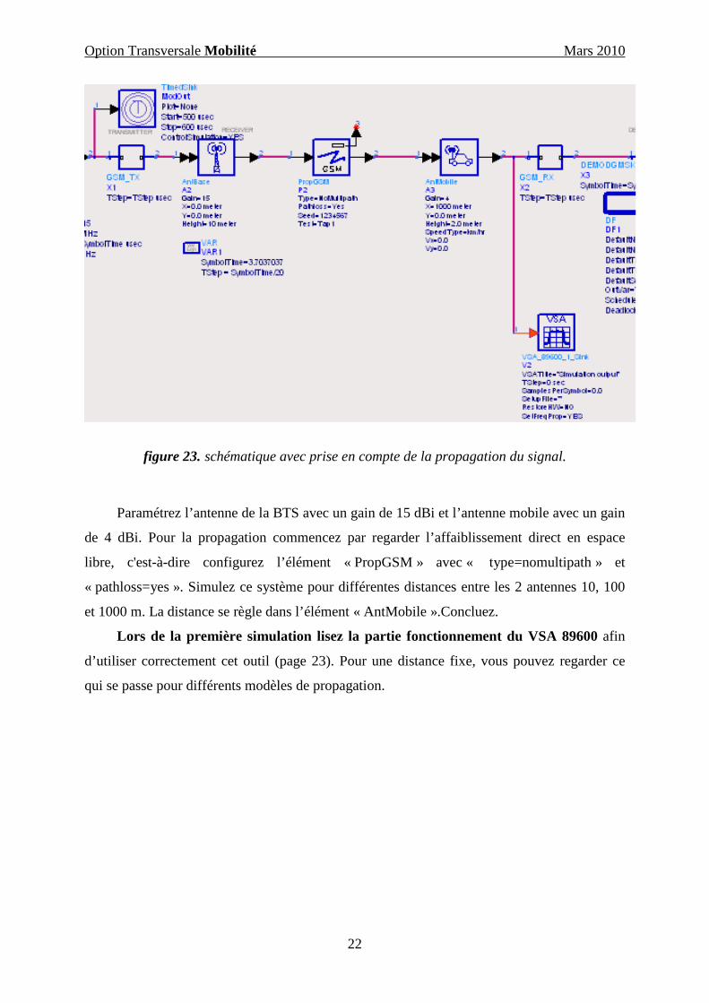
figure 23. schématique avec prise en compte de la propagation du signal.
Paramétrez l’antenne de la BTS avec un gain de 15 dBi et l’antenne mobile avec un gain
de 4 dBi. Pour la propagation commencez par regarder l’affaiblissement direct en espace
libre, c'est-à-dire configurez l’élément « PropGSM » avec « type=nomultipath » et
« pathloss=yes ». Simulez ce système pour différentes distances entre les 2 antennes 10, 100
et 1000 m. La distance se règle dans l’élément « AntMobile ».Concluez.
Lors de la première simulation lisez la partie fonctionnement du VSA 89600 afin
d’utiliser correctement cet outil (page 23). Pour une distance fixe, vous pouvez regarder ce
qui se passe pour différents modèles de propagation.
Option Transversale Mobilité Mars 2010
23
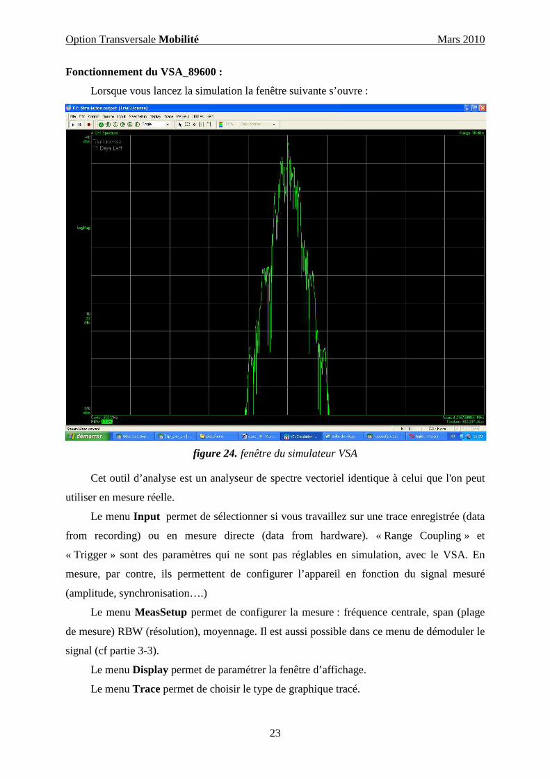
Fonctionnement du VSA_89600 :
Lorsque vous lancez la simulation la fenêtre suivante s’ouvre :
figure 24. fenêtre du simulateur VSA
Cet outil d’analyse est un analyseur de spectre vectoriel identique à celui que l'on peut
utiliser en mesure réelle.
Le menu Input permet de sélectionner si vous travaillez sur une trace enregistrée (data
from recording) ou en mesure directe (data from hardware). « Range Coupling » et
« Trigger » sont des paramètres qui ne sont pas réglables en simulation, avec le VSA. En
mesure, par contre, ils permettent de configurer l’appareil en fonction du signal mesuré
(amplitude, synchronisation….)
Le menu MeasSetup permet de configurer la mesure : fréquence centrale, span (plage
de mesure) RBW (résolution), moyennage. Il est aussi possible dans ce menu de démoduler le
signal (cf partie 3-3).
Le menu Display permet de paramétrer la fenêtre d’affichage.
Le menu Trace permet de choisir le type de graphique tracé.
Option Transversale Mobilité Mars 2010
24
Le menu Marker permet de positionner des marqueurs et d’utiliser des fonctions de
calculs.
Affichez une seule fenêtre d’analyse à l’écran (« single ») et sélectionnez le spectre.
Pour cela cliquez sur Trace/data/spectrum. Positionnez le pointeur de la souris sur le graphe
et cliquez sur le bouton droit et Y auto scale.
Puis dans le menu MeasSetup réglez le span à 2 MHz, le nombre de point de mesure à 3200 et
la résolution à 3KHz.
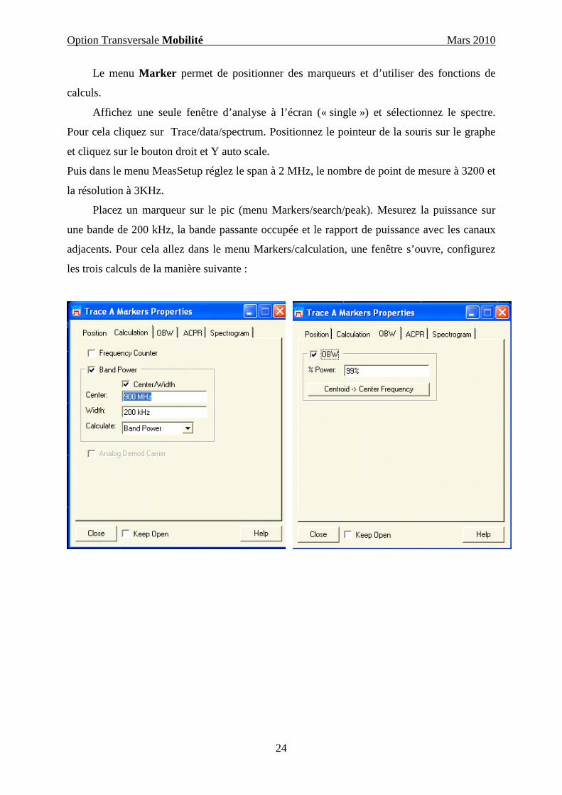
Placez un marqueur sur le pic (menu Markers/search/peak). Mesurez la puissance sur
une bande de 200 kHz, la bande passante occupée et le rapport de puissance avec les canaux
adjacents. Pour cela allez dans le menu Markers/calculation, une fenêtre s’ouvre, configurez
les trois calculs de la manière suivante :

Option Transversale Mobilité Mars 2010
25
figure 25. fenêtre de paramétrage des calculs
Une fois ces paramètres réglés vous devez obtenir l’écran suivant avec le spectre et les
résultats des calculs en dessous de la courbe.
figure 26. spectre avec l’OBW et l’ACPR
Comparez les résultats de l’ACPR avec la norme GSM (cf figure 27 tableau norme
GSM).
Option Transversale Mobilité Mars 2010
26
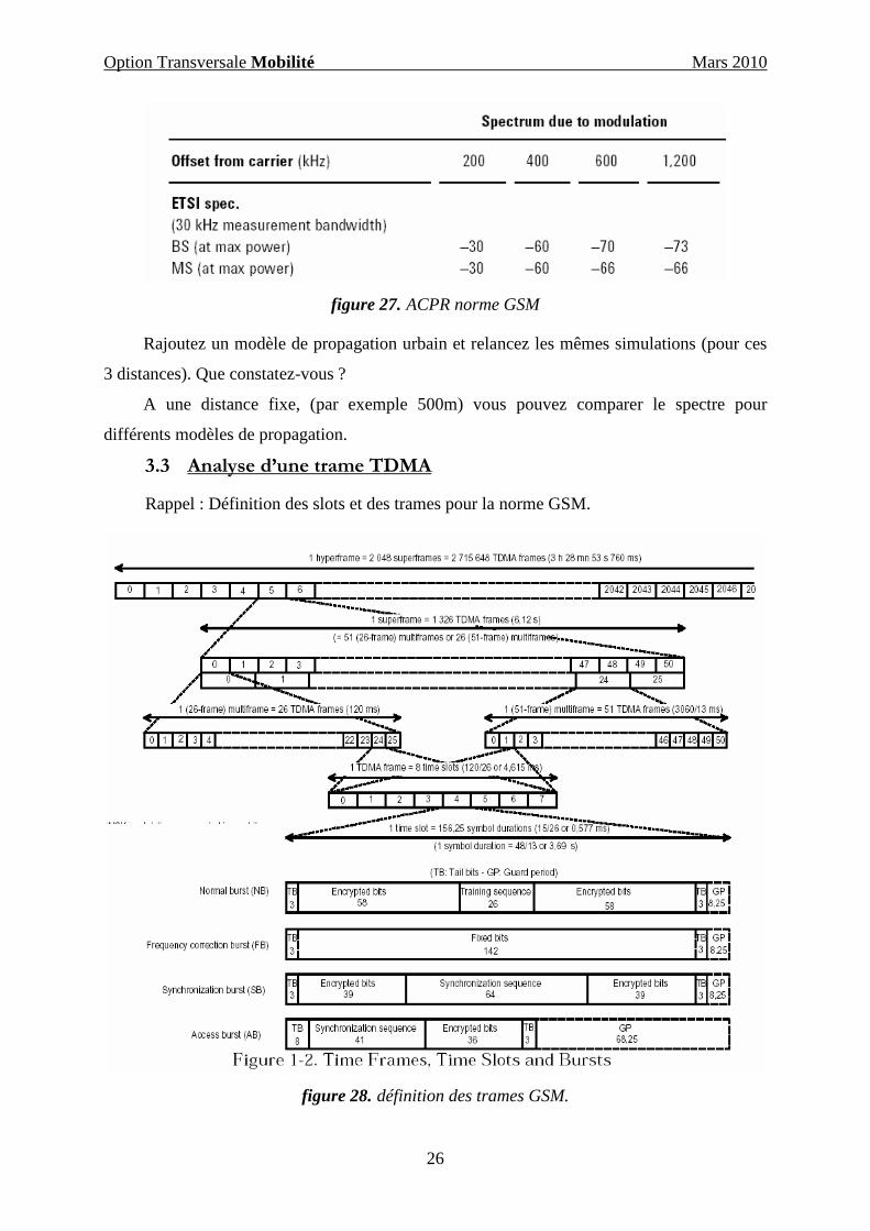
figure 27. ACPR norme GSM
Rajoutez un modèle de propagation urbain et relancez les mêmes simulations (pour ces
3 distances). Que constatez-vous ?
A une distance fixe, (par exemple 500m) vous pouvez comparer le spectre pour
différents modèles de propagation.
3.3 Analyse d’une trame TDMA
Rappel : Définition des slots et des trames pour la norme GSM.
figure 28. définition des trames GSM.
Option Transversale Mobilité Mars 2010
27
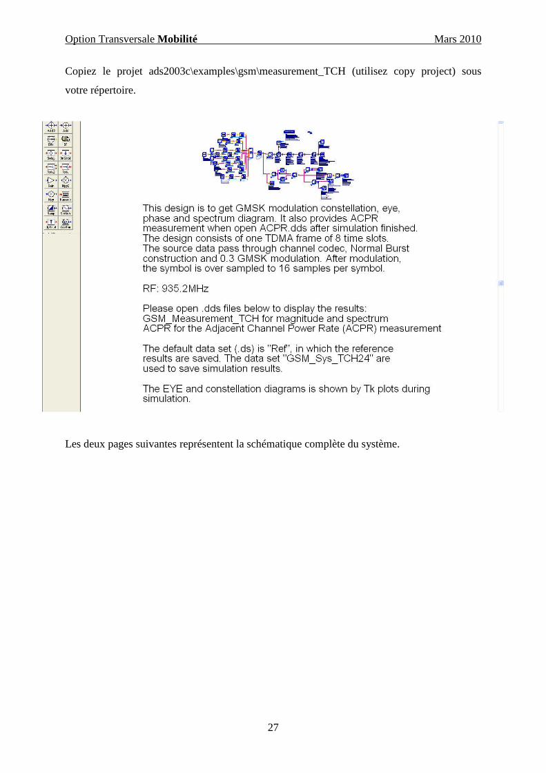
Copiez le projet ads2003c\examples\gsm\measurement_TCH (utilisez copy project) sous
votre répertoire.
Les deux pages suivantes représentent la schématique complète du système.

Option Transversale Mobilité Mars 2010
28
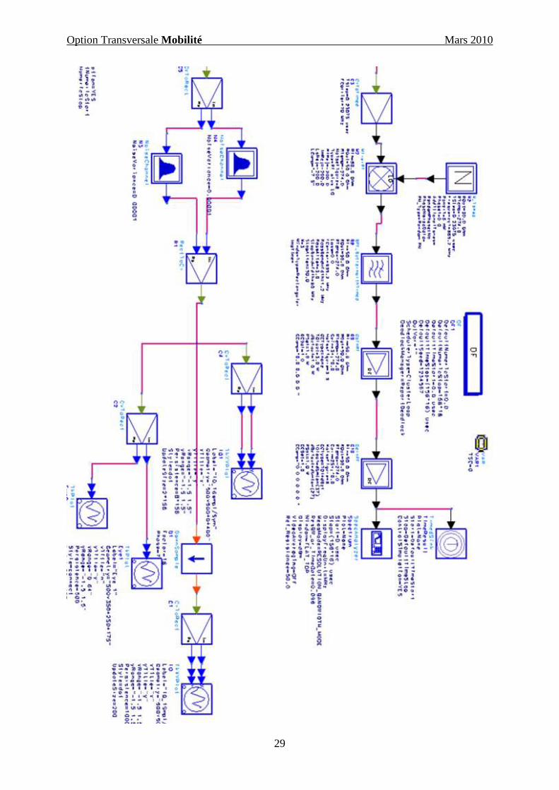
Option Transversale Mobilité Mars 2010
29
Option Transversale Mobilité Mars 2010
30
Avant d’analyser ce système, regardez comment la trame est constituée (durée des slots,
composition des slots…). Simulez le système pour différentes configurations (en désactivant
certains slots). Lors de la simulation vous visualiserez le diagramme de l’œil et la
constellation directement sur des fenêtres de visualisation. Une fois la simulation terminée
ouvrez les fichiers data set correspondant et analysez le spectre et le signal en bande de base.
Commentez les résultats.
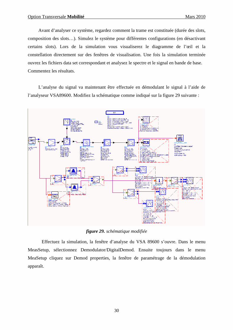
L’analyse du signal va maintenant être effectuée en démodulant le signal à l’aide de
l’analyseur VSA89600. Modifiez la schématique comme indiqué sur la figure 29 suivante :
figure 29. schématique modifiée
Effectuez la simulation, la fenêtre d’analyse du VSA 89600 s’ouvre. Dans le menu
MeasSetup, sélectionnez Demodulator/DigitalDemod. Ensuite toujours dans le menu
MeaSetup cliquez sur Demod properties, la fenêtre de paramétrage de la démodulation
apparaît.
Option Transversale Mobilité Mars 2010
31
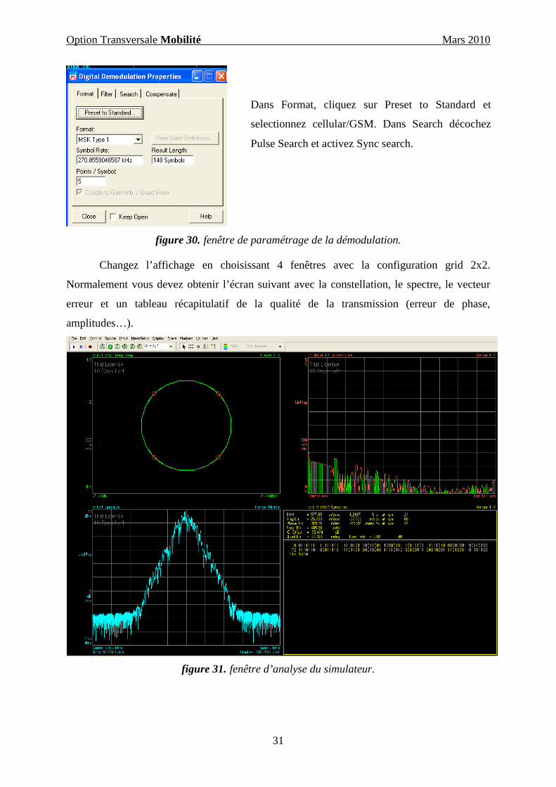
figure 30. fenêtre de paramétrage de la démodulation.
Changez l’affichage en choisissant 4 fenêtres avec la configuration grid 2x2.
Normalement vous devez obtenir l’écran suivant avec la constellation, le spectre, le vecteur
erreur et un tableau récapitulatif de la qualité de la transmission (erreur de phase,
amplitudes…).
figure 31. fenêtre d’analyse du simulateur.
Dans Format, cliquez sur Preset to Standard et
selectionnez cellular/GSM. Dans Search décochez
Pulse Search et activez Sync search.

Option Transversale Mobilité Mars 2010
32
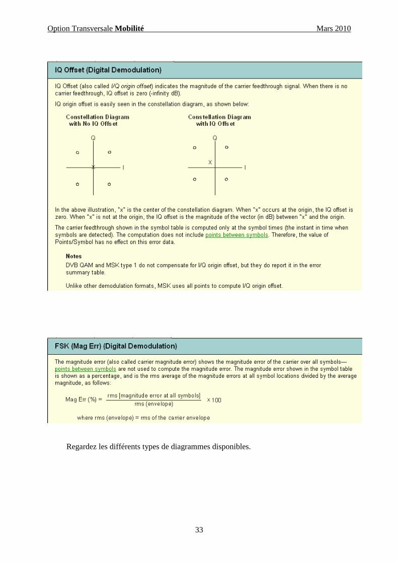
Les tableaux suivants présentent quelques définitions des calculs effectués par le
logiciel. Pour plus de détails sur le fonctionnement du 89600, une aide est disponible en
cliquant sur Help/tutorials.
Option Transversale Mobilité Mars 2010
33
Regardez les différents types de diagrammes disponibles.

Option Transversale Mobilité Mars 2010
34
3.4 Analyse d’un signal GSM pour une liaison montante et
descendante.
Dans cette partie, vous étudierez deux sources GSM. La première génère un signal au
format GSM d’une liaison montante (mobile vers station de base), la seconde délivre un
signal suivant le format descendant.
Créez un nouveau projet.
Analyse de la voie montante :
Dans la fenêtre « schématique », prenez la source GSM qui se trouve dans :
DesignGuide\RFsystem\Additional Analog/RF Sources\ GSM/EDGE \reverse Link (GSM)
(barre des taches en haut de la fenêtre schématique)
Expliquez le fonctionnement de ce composant. Un descriptif de ce composant est
détaillé pages 35-36
Ouvrez la fenêtre d’analyse et les différentes courbes et équations. Simulez le système pour
différentes configurations (avec et sans saut de fréquences, différents trafics…)
Option Transversale Mobilité Mars 2010
35
Component Name: GSM_EDGE_Uplink_GMSK_SrcParameter(s): (name: description, type, range of usage) Carrier_Freq: The center frequency of the output RF spectrum (if frequency hopping is not used, Carrier_Freq is the carrier frequency of the modulated signal), real. Pav: Relative average output power of the modulator, real. Slot_x: Specifies whether a data burst is to be transmitted within slot x of each frame. Use a 1 for a full-rate channel, 2 for a half- rate channel on sub-channel 0, 3 for a half-rate channel on sub- channel 1, and 0 for no traffic, integer, >= 0 and <= 3. TSC_Num: The training sequence code that is inserted into each data burst, integer, >= 0 and <= 7. Symbol_Rate: The modulation symbol rate. This design and its sub-designs expect a symbol rate of 270.8333... ksym/s, real, > 0. Frequency_Hop: Enables or disables frequency hopping, string, "Yes" or "No". Mobile_Allocation: Specifies the number of RF channels utilized for frequency hopping, integer, >= 1 and <= 64. Channel_Spacing: The frequency difference (measured in terms of 200 kHz channels) between the channels making up the Mobile_Allocation, integer, > 1. Hopping_Sequence_Num: The hopping sequence number, integer, >= 0 and <= 63. Mobile_Allocation_Offset: The RF channel index offset for this mobile, integer, >= 0 and <= (Mobile_Allocation - 1). Delay_Time: The first TDMA frame begins precisely 6 modulation symbol periods after Delay_Time, real, >= 0.Input(s): None.Output(s): Modulated GMSK signal, ports 1 and 2.
Description: GSM_EDGE_Uplink_GMSK_Src generates a TDMAGMSK modulated user/mobile station (MS) signal. This component isintended for use with envelope simulations.
GSM utilizes an 8 slot frame to implement TDMA. Each slot has aduration of 156.25 symbol periods. The slots of a frame are identified asslot zero through seven. A single physical channel is equivalent to thesame slot of each frame being utilized to transmit a data burst. AMS may be allocated one or more physical channels, depending uponthe uplink data bandwidth required by the MS. The 156.25 symbolperiods of a slot include a guard period that is at least 8.25 symbolperiods in duration and tail bits/symbol periods that precede and followthe portion of the slot during which useful data is transmitted. Seesection 5 of [1] for an overview of the TDMA aspect of the GSM system.
In regard to this component, the number of physical channels that willform the transmitted MS signal depends upon the Slot_x parameters.If the Slot_x parameter is set to 1, a full-rate traffic channel is allocatedto slot x. If Slot_x is set to 2 or 3, a half-rate traffic channel is allocatedto slot x, with a 2 corresponding to sub-channel 0 and a 3 to sub-channel 1. If Slot_x is set to 0 no traffic is allocated to slot x.
Although the GSM system utilizes four different types of data bursts fortransmission during a slot (namely: Normal, Frequency Correction, Synchronization, and Access Bursts), this component only implementsa Normal Burst. See section 5.2 of [2] (and the GSM_EDGE_Uplink_GMSK_IQ design) for more information.
The timing of the output signal is referenced to the start of the firstframe (or part thereof) transmitted. The start of the symbol period ofthe first symbol (the first tail bit/symbol period) of slot zero is precisely 6 symbol periods after Delay_Time.
The power of the transmitted signal is ramped up and down over thecourse of three bit/symbol periods just before the start of the databurst and after the data burst. The Normal Burst has a duration of148 symbol periods, including the tail bits/symbols at the start andend of the burst. During the ramp up and ramp down dummy bitsare used to determine the output state of the modulator. The shapeof the ramp up and ramp down is derived by time windowing themodulator output with a raised cosine window.
Each normal burst transmitted includes an embedded trainingsequence code. The same training sequence code is embeddedwithin all bursts that are transmitted. The training sequence codeis specified by the TSC_Num parameter and is selected from afamily of 8 (indexed 0 through 7) different codes. See section 5.2of [2]. The data portion of each normal burst is generatedrandomly using an independent identically distributed numbergnerator.
The GSM system utilizes channels having a bandwidth of 200 kHz. Iffrequency hopping is not enabled, the Carrier_Freq parameter specifies the carrier frequency of the generated signal. If frequencyhopping is enabled, the carrier frequency of the generated signalchanges from frame to frame in accordance with a frequency hoppingalgorithm - see section 6 of [1] for an overview of frequency hoppingand section 6.2 (specifically, 6.2.3) for details of the frequencyhopping algorithm. The number of channels utilized when frequencyhopping is enabled is determined by the Mobile_Allocationparameter. For example, if the Mobile_Allocation parameter is setto N, the transmitted signal will hop amongst N 200 kHz widechannels whose centre frequencies are separated from one anotherby 200 kHz x Channel_Spacing. If N is an even number, the Carrier_Freq parameter specifies the mid-point of the band of N channels; whereas, if N is an odd number, the Carrier_Freq parameter specifies the center frequency of the center channel of theband of N channels.
The GSM_EDGE_Uplink_GMSK_Src component is able to operate with 4, 8 or 16 samples per modulated symbol. The number of samples per modulated symbol will depend upon the size of thetime-step of the simulation. If frequency hopping is no enabled 4samples per symbol can be used, however, if frequency hoppingis enabled, 8 or 16 samples per symbol will have to be used, withreference to the value of the Mobile_Allocation parameter.
A quadrature modulator is used here to implement GMSK. TheGSM_EDGE_Uplink_GMSK_IQ sub-component generates therequired I and Q modulating signals. See theGSM_EDGE_Uplink_GMSK_IQ sub-component for more information. GMSK modulation as implemented here is described in section 2 of [4].
Besides the limitations described above, this component doesnot implement the logical channel combinations and mappingdescribed in section 6.5 of [2], or those aspects of the specifications describing the cordless telephone system (CTS)and COMPACT mode.
All references are to Release 5 of the following GSM/EDGE specifications:
[1] 3GPP TS 45.001 V5.3.0 (2002-04) "Physical Layer On the Radio Path"[2] 3GPP TS 45.002 V5.5.0 (2002-04) "Multiplexing and Multiple Access On the Radio Path"[3] 3GPP TS 45.003 V5.5.0 (2002-04) "Channel Coding"[4] 3GPP TS 45.004 V5.0.0 (2001-11) "Modulation" (Note: this document states that it is from Release 4, however its version indicates that it is from Release 5, and the 3GPP document status table states that it is from Release 5) [5] 3GPP TS 45.005 V5.3.0 (2002-04) "Radio Transmission and Reception"
A helpful document for interpreting the above specifications is [6] 3GPP TR 21.995 V5.3.0 (2002-03) "Vocabulary for 3GPP Specifications"
Option Transversale Mobilité Mars 2010
36
Component Name: GSM_EDGE_Uplink_GMSK_IQParameter(s): (name: description, type, range of usage) SymRate: The modulation symbol rate. This design expects a symbol rate of 270.8333... ksym/s, real, > 0. Slotx: Specifies whether a data burst is to be transmitted within slot x of each frame. A value other than 0 will result in slot x containing a data burst, integer. TSCNum: The training sequence code number that is inserted into each data burst, integer, >= 0 and <= 7. FrequencyHop: Enables or disables frequency hopping, string, "Yes" or "No". MobileAllocation: Specifies the number of RF channels utilized for frequency hopping, integer, >= 1 and <= 64. ChannelSpacing: The frequency difference (measured in terms of 200 kHz channels) between the channels making up the MobileAllocation, integer, > 1. HoppingSequenceNum: The hopping sequence number, integer, >= 0 and <= 63. MobileAllocationOffset: The RF channel index offset for this mobile, integer, >= 0 and <= (Mobile_Allocation - 1). DelayTime: The first TDMA frame begins precisely 6 modulation symbol periods after this time, real, >= 0.Input(s): None.Output(s): In-phase baseband GMSK signal, ports 1 and 2. Quadrature baseband GMSK signal, ports 3 and 4.
Description: GSM_EDGE_Uplink_GMSK_IQ generates the in-phaseand quadrature baseband signals that toegether form a baseband GSM TDMA GMSK modulated user/mobile station (MS) signal. This component is a sub-component of the GSM_EDGE_Uplink_GMSK_Srccomponent that is intended for use with envelope simulations. Seethe notes accompanying the GSM_EDGE_Uplink_GMSK_Src designfor more information.
The operations performed within this component can be categorized using three broad categores - those operations that pertain to TDMA,those that pertain to FDMA, and those that pertain to GMSK signaling.The notes accompanying the GSM_EDGE_Uplink_GMSK_Src designgive an overview of the TDMA and FDMA aspects of the RF GMSKmodulated signal that it produces. Since the GSM_EDGE_Uplink_GMSK_Src design performs quadraturemodulation using a fixed carrier frequency (i.e. frequency hopping isimplemented at baseband, not during modulation/upconversion), allof the same TDMA and FDMA aspects apply to the complex baseband GMSK signal formed by the in-phase and quadratureoutputs of this component.
The primary TDMA elements are implemented using:
an 8 element array that is used to determine whether data is to be transmitted during each of the 8 slots of a frame;
three alternative 26 element arrays that are used to determine whether data is to be transmitted during each of the 26 frames of a 26 frame multiframe;
a raised cosine window at port 6 of the FDD7P component to ramp the output signals' amplitude on and off during a period of 3 symbols prior to and following the 148 symbols of a burst;
a time-step counter (that is reset after each frame) from which a symbol trigger and counter, slot trigger and counter, and frame counter are derived and used to control the signal generation.
As stated, frequency hopping is implemented by shifting the spectrumof a baseband GMSK signal to the appropriate location in thespectrum according to the frequency hopping algorithm - see section6.2.3 of [2]. The complete algorithm is implemented. The algorithmutilizes the frame number associated with each TDMA frame asdescribed in sections 3.3.2.2.1 and 4.3.3 of [2]. It is assumed that thefirst TDMA frame is frame number (FN) zero. Moreover, it is assumedthat the output of the frequency hopping sequence algorithm, namelythe Mobile Allocation Index (MAI) has a one-to-one, from lowestfrequency to highest frequency, correspondence with each of the channels that make up the MobileAllocation. That is, if MobileAllocation is set to N, the zero'th channel is the lowest ofthe N channels that make up the band of channels amongst whichfrequency hopping may occur, with the N-1 channel being the highestchannel in the band (MAI takes on a value between 0 and N-1).
The actual spectrum shifting of the baseband GMSK signal is carried out using a complex multiplication using the derived MAIin combination with the ADS global variable 'time'.
GMSK modulation for GSM is described in section 2 of [4]. Thespecification provides for differential encoding, filtering using aGaussian pulse shape and frequency modulation by the aggregatephase formed at the output of the Gaussian pulse shaping filter. In place of a frequency modulator, it is possible to use aquadrature modulator to form the same modulated signal.Furthermore, since the Gaussian filter has a finite length, itsoutput can be determined using a finite number of input bits toform an address into a look-up table of prototype waveforms.For instance, see the ADS GSM signal processing componentGSM_Rom.dsn, as well as: A. Bodas & K. Feher, "Low Complexity GSM Modulator for Integrated Circuit Implementation" 1996 Proceedings Ninth Annual IEEE International ASIC Conference and Exhibit 103, A.E. Jones & J.G. Gardiner, "Generation of GMSKUsing Direct Digital Synthesis" 1992 IEE Colloquium on Implementations of Novel Hardware for Radio Systems 7/1, and Yik-Chung Wu & Tung-Sang Ng, "New Implementation of a GMSKDemodulator in Linear Software Radio Receivers" vol. 2, 2000 The11th IEEE International Symposium on Personal, Indoor and MobileCommunications 1049.
The starting point for the GMSK modulator is the formation of the bitstream that is to be transmitted during a slot that is active. The bitstream is derived with the aid of an array that forms a template ofa normal burst. The template contains the bits that are fixed forevery burst, namely: the dummy bits that precede and follow thetail bits of the burst, the tail bits themselves, and the TrainingSequence Code bits as specified by the TSCNum parameter. Thedata bits of the burst are generated by an indepedent identicallydistributed random number generator that produces zeros and oneswith equal probability. The data bits are stored for the duration ofa symbol period at port 3 of the FDD7P component.
The data bits are differentially encoded, with the resultant bitsstored in-turn for the duration of a symbol period at port 4 of theFDD7P component.
Using the current differentially encoded bit, and the past fourencoded bits, a 5 bit index is generated and stored for the durationof a symbol period at port 7 of the FDD7P component. Using this5 bit index a base address is formed to reference a prototypewaveform representing the aggregate phase of 5 consecutivesymbols over the course of the symbol period of the center symbolof the 5 symbols. To this 5 symbol aggregate phase must beadded the contribution due to the symbols that preceded thecurrent 5 symbol block. This contribution is calculated once persymbol period and is stored at port 5 of the FDD7P component.
Once the aggregate phase is determined, it is used to calculatethe amplitude of the in-phase and quadrature components thattogether form the baseband GMSK signal and appear at ports 1and 2, respectively, of the FDD7P component.
All references are to Release 5 of the following GSM/EDGE specifications:
[1] 3GPP TS 45.001 V5.3.0 (2002-04) "Physical Layer On the Radio Path"[2] 3GPP TS 45.002 V5.5.0 (2002-04) "Multiplexing and Multiple Access On the Radio Path"[3] 3GPP TS 45.003 V5.5.0 (2002-04) "Channel Coding"[4] 3GPP TS 45.004 V5.0.0 (2001-11) "Modulation" (Note: this document states that it is from Release 4, however its version indicates that it is from Release 5, and the 3GPP document status table states that it is from Release 5) [5] 3GPP TS 45.005 V5.3.0 (2002-04) "Radio Transmission and Reception"
A helpful document for interpreting the above specifications is [6] 3GPP TR 21.995 V5.3.0 (2002-03) "Vocabulary for 3GPP Specifications"
Option Transversale Mobilité Mars 2010
37
Analyse de la voie descendante :
Ouvrez un nouveau projet.
Dans la fenêtre « schématique », prenez la source GSM qui se trouve dans :
DesignGuide\RFsystem\Additional Analog/RF Sources\ GSM/EDGE \Forward Link (GSM).
La principale différence entre la voie montante et le voie descendante est la présence
d’un signal balise (BCCH) émis par la station de base pour se synchroniser avec un mobile.
La description des éléments utilisés dans ce système se trouve sur les 3 pages suivantes.
Option Transversale Mobilité Mars 2010
38
The timing of the output signal is referenced to the start of the firstframe (or part thereof) transmitted. The start of the symbol period ofthe first symbol (the first tail bit/symbol period) of slot zero is precisely 6 symbol periods after Delay_Time (recall that all down-link frames are time aligned).
The power of the transmitted signal is ramped up and down over thecourse of three bit/symbol periods just before the start of each databurst and after the data burst. The Normal Burst has a duration of148 symbol periods, including the tail bits/symbols at the start andend of the burst. During the ramp up and ramp down dummy bitsare used to determine the output state of the modulator. The shapeof the ramp up and ramp down is derived by time windowing theeach burst that is to be transmitted with a raised cosine window.
Each Normal Burst transmitted includes an embedded trainingsequence code. The same training sequence code is embeddedwithin all bursts that are transmitted. The training sequence codeis specified by the TSC_Num parameter and is selected from afamily of 8 (indexed 0 through 7) different codes. See section 5.2of [2]. The data portion of each normal burst is generatedrandomly using an independent identically distributed numbergnerator.
The GSM system utilizes channels having a bandwidth of 200 kHz. The Mobile_Allocation parameter specifies the number of RF channels(each having a bandwidth of 200 kHz) that are available for the downlink. The centre frequency of the RF channels are spaced200 kHz x Channel_Spacing apart. The Carrier_Freq parameter specifies the centre frequency of the band of RF channels. If N is aneven number, the Carrier_Freq parameter specifies the mid-point ofthe band of N channels; whereas, if N is an odd number, theCarrier_Freq parameter specifies the center frequency of the centerchannel of the band of N channels. The band of RF channels is indexed from the channel lowest in frequency to the channel highestin frequency, with the index running from 0 to N-1. The C0_Channel_Number parameter specifies the index of the RF channelthat is to be the C0 carrier. The BCCH physical channels aretransported on the C0 carrier at all times, whether frequency hoppingis enabled or disabled. If frequency hopping is NOT enabled, eachgroup of traffic channels is associated with a single RF carrier, withthe Tr0 group being matched with the C0 carrier, and each successive traffic group being matched with the next higher RF channel (rolling over to the channel having index 0 if index N-1 is exceeded). If frequency hopping is enabled, the carrier frequency ofeach physical channel (other than those associated with BCCH logical channels) changes from frame to frame in accordance with afrequency hopping algorithm - see section 6 of [1] for an overview offrequency hopping and section 6.2 (specifically, 6.2.3) for details ofthe frequency hopping algorithm. The physical channels of eachtraffic group that coincide with the BCCH physical channels, i.e. those physical channels occupying the same slot, hop over a frequency range that does NOT include the C0 carrier. Whereas, thephysical channels of each traffic group (including all of the Tr0 trafficchannels) that do not coincide with the BCCH physical channelshop over the entire frequency range defined by theMobile_Allocation parameter.
The GSM_EDGE_Downlink_GMSK_Src component is able to operate with 4, 8 or 16 samples per modulated symbol. The number of samples per modulated symbol depends upon the size of thetime-step of the simulation. If frequency hopping is not enabled,4 samples per symbol can be used, however, if frequency hoppingis enabled, 8 or 16 samples per symbol will have to be used, withreference to the value of the Mobile_Allocation parameter.
A quadrature modulator is used to implement GMSK. TheGSM_EDGE_Downlink_GMSK_IQ and GSM_EDGE_Downlink_GMSK_BCCH_IQ sub-componentsgenerate the required I and Q modulating signals. See both ofthese sub-component for more information. GMSK modulationas implemented here is described in section 2 of [4].
Besides the limitations described above, this component doesnot implement the logical channel combinations and mappingdescribed in section 6.5 of [2] (other than iv and vi of section 6.4.1that apply to the BCCH channel(s)), or those aspects of the specifications describing the cordless telephone system (CTS)and COMPACT mode.
Component Name: GSM_EDGE_Downlink_GMSK_SrcParameter(s): (name: description, type, range of usage) Carrier_Freq: The center frequency of the output RF multicarrier signal, real. Pav: Relative average output power of the modulator, real. BCCH_Channels: The number of BCCH physical channels (slots) to be transmitted. The BCCH physical channels are always associated with the C0 RF carrier and utilize, in order, slot 0, 2, 4 and 6, depending upon the number of BCCH physical channels, integer, >= 0 and <= 4. BCCH_Gain: Relative gain of BCCH physical channel(s) and dummy bursts on C0, real, >= 0.0. C0_Channel_Number: Index of the RF channel for the C0 (BCCH carrier) RF carrier, integer, >= 0 and <= (Mobile_Allocation - 1). Slot_Usage_BCCH_Tr0: An 8 element array that specifies whether a data burst (traffic) is to be transmitted using each of the physical channels (slots) associated with the Tr0 group of traffic channels. A value other than 0 will result in the associated slot being filled with a data burst and having a relative gain as specified by the value entered. Note: Slots 0, 2, 4, or 6 may be specified to be filled with data bursts if not otherwise allocated for BCCH data, 8 element real array, each element >= 0.0. Slot_Usage_Trx: An 8 element array that specifies whether a data burst (traffic) is to be transmitted using each of the physical channels (slots) associated with the Trx group of traffic channels. A value other than 0 will result in the associated slot being filled with a data burst having a relative gain as specified by the value entered, 8 element real array, each element >= 0.0. TSC_Num: The training sequence code that is inserted into each data burst, integer, >= 0 and <= 7. Symbol_Rate: The modulation symbol rate. This design and its sub-designs expect a symbol rate of 270.8333... ksym/s, real, > 0. Frequency_Hop: Enables or disables frequency hopping, string, "Yes" or "No". Mobile_Allocation: Specifies the number of RF channels utilized for frequency hopping, integer, >= 1 and <= 64. Channel_Spacing: The frequency difference (measured in terms of 200 kHz channels) between the channels making up the Mobile_Allocation, integer, > 1. Hopping_Sequence_Num: The hopping sequence number, integer, >= 0 and <= 63. Delay_Time: The first TDMA frame begins precisely 6 modulation symbol periods after this time, real, >= 0. R_Out: The output resistance of the signal source, real, >= 0.01.Input(s): None.Output(s): RF GMSK modulated multicarrier signal, ports 1 and 2.
Description: GSM_EDGE_Downlink_GMSK_Src generates a TDMAmulticarrier GMSK modulated base station (BS) signal. The outputmulticarrier signal can contain from 1 to 8 modulated carriers. Thiscomponent is intended for use with envelope simulations. GSM_EDGE_Downlink_GMSK_Src has two sub-components: GSM_EDGE_Downlink_GMSK_BCCH_IQ.dsn, and GSM_EDGE_Downlink_GMSK_IQ.dsn.See the notes accompanying these sub-component designs files formore information regarding their operation.
GSM utilizes an 8 slot frame to implement TDMA. Each slot has aduration of 156.25 symbol periods. The slots of a frame are identified asslot zero through seven. A single physical channel is equivalent to thesame slot of each successive frame being utilized to transmit a data burst (note: this says nothing about the carrier frequency of the data burst). A mobile station (MS) may be allocated one or more physicalchannels, depending upon the required downlink data bandwidth. The156.25 symbol periods of a slot include a guard period that is 8.25 symbol periods in duration and tail bits/symbol periods that precedeand follow the portion of the slot during which useful data is transmitted.The frames of all downlink RF carriers are time aligned - see section4.3.1 of [2]. See section 5 of [1] for an overview of the TDMA aspectof the GSM system.
The number of physical channels that will form the transmitted BS signaldepends upon the BCCH_Channels, SlotUsage_BCCH_Tr0 and SlotUsage_Trx parameters. The BCCH_Channels parameter determinesthe number of physical channels that are allocated to carry broadcastcontrol channel (BCCH - a logical channel) information. TheBCCH_Channels parameter will typically be set to one, however, upfour physical channels can be allocated for BCCH information. TheseBCCH physical channels, whether one or up to four, are associatedwith an RF carrier identified as channel C0. The C0 RF carrier neverhops. The BCCH channels are utilize slot(s) 0, 2, 4 and 6, dependingupon the number of BCCH channels. Slot 0 is always allocated aBCCH channel first, then in order of decreasing priority, slot 2, 4 and 6.The BCCH channel that is assigned to slot 0, also includessynchronization and frequency correction information.
The SlotUsage_BCCH_Tr0 and SlotUsage_Trx parameters determine thenumber of physical channels that are allocated for data traffic. Aphysical channel is allocated for data traffic by setting its correspondingelement of one of the parameter arrays to a non-zero value - with thefirst element of each array corresponding to slot 0, the second to slot 1,and so on. The non-zero value entered also specifies the relativepower of that traffic channel. Each ...Trx group of traffic channels refers to a set of channels having a common RF carrier. The SlotUsage_BCCH_Tr0 parameter determines the status of the physical channel traffic group whose size is reduced due to the existence of anyBCCH channels. That is, if the BCCH_Channels parameter is set to one, the value of the first element of the SlotUsage_BCCH_Tr0 array isignored. Each physical channel that is allocated for data traffic resultsin a Normal Burst being transmitted. See section 5.2 of [2] (and the GSM_EDGE_Downlink_GMSK_BCCH_IQ andGSM_EDGE_Downlink_GMSK_IQ designs) for more information.
All references are to Release 5 of the following GSM/EDGE specifications:
[1] 3GPP TS 45.001 V5.3.0 (2002-04) "Physical Layer On the Radio Path"[2] 3GPP TS 45.002 V5.5.0 (2002-04) "Multiplexing and Multiple Access On the Radio Path"[3] 3GPP TS 45.003 V5.5.0 (2002-04) "Channel Coding"[4] 3GPP TS 45.004 V5.0.0 (2001-11) "Modulation" (Note: this document states that it is from Release 4, however its version indicates that it is from Release 5, and the 3GPP document status table states that it is from Release 5) [5] 3GPP TS 45.005 V5.3.0 (2002-04) "Radio Transmission and Reception"
A helpful document for interpreting the above specifications is [6] 3GPP TR 21.995 V5.3.0 (2002-03) "Vocabulary for 3GPP Specifications"
Option Transversale Mobilité Mars 2010
39
Component Name: GSM_EDGE_Downlink_GMSK_BCCH_IQParameter(s): (name: description, type, range of usage) SymRate: The modulation symbol rate. This design expects a a symbol rate of 270.8333... ksym/s, real, > 0. BCCHChannels: The number of BCCH physical channels (slots) to be transmitted. The BCCH physical channels are always associated with the C0 RF carrier and utilize, in order, slot 0, 2, 4 and 6, depending upon the number of BCCH physical channels, integer, >= 0 and <= 4. BCCHGain: Relative gain of BCCH physical channel(s) and dummy bursts on C0, real, >= 0.0. SlotUsage: An 8 element array that specifies whether a data burst (traffic) is to be transmitted using each of the physical channels (slots) associated with the Tr0 group of traffic channels. A value other than 0 will result in the associated slot being filled with a data burst and having a relative gain as specified by the value entered. Note: Slots 0, 2, 4, or 6 may be specified to be filled with data bursts if not otherwise allocated for BCCH data, 8 element real array, each element >= 0.0. TSCNum: The training sequence code that is inserted into each data burst, integer, >= 0 and <= 7. FrequencyHop: Enables or disables frequency hopping, string, "Yes" or "No". MobileAllocation: Specifies the number of RF channels utilized for frequency hopping, integer, >= 1 and <= 64. ChannelSpacing: The frequency difference (measured in terms of 200 kHz channels) between the channels making up the Mobile_Allocation, integer, > 1. HoppingSequenceNumber: The hopping sequence number, integer, >= 0 and <= 63. MobileAllocationOffset: The RF channel index offset for the C0 carrier and the Tr0 group of traffic channels, integer, >= 0 and <= (MobileAllocation - 1). Delay: The first TDMA frame begins and is output precisely 4 modulation symbol periods after this time, real, >= 0.Input(s): None.Output(s): In-phase baseband GMSK signal, ports 1 and 2. Quadrature baseband GMSK signal, ports 3 and 4.
Description: GSM_EDGE_Downlink_GMSK_BCCH_IQ generatesthe in-phase and quadrature GMSK baseband signals that together form theGSM TDMA GMSK signal made up from those physical channels allocatedfor the transmission of broadcast control channel (BCCH) information andthe physical channels of the Tr0 traffic channel group. This component is asub-component of the GSM_EDGE_Downlink_GMSK_Src component thatis intended for use in envelope simulations. See the notes accompanyingthe GSM_EDGE_Uplink_GMSK_Src design for more information.
The operations performed within this component can be grouped into threebroad categores - those operations that pertain to TDMA, those that pertainto FDMA, and those that pertain to GMSK signaling. The notes accompanying the GSM_EDGE_Uplink_GMSK_Src design provide anoverview of the TDMA and FDMA aspects of the basestation multicarrierRF GMSK modulated signal that it produces. Since the GSM_EDGE_Uplink_GMSK_Src design performs quadrature modulationusing a fixed carrier frequency (i.e. frequency hopping is implemented atbaseband, not during modulation/upconversion), all of the TDMA and FDMAaspects that are described there apply to the complex baseband GMSKsignal formed by the in-phase and quadrature outputs of this component.
The primary TDMA elements are implemented by:
an 8 element array that is used to determine whether data is to be transmitted during each of the 8 slots of a frame, and if so, the relative power at which the data is transmitted;
a raised cosine window at port 6 of the FDD7P component to ramp the output signals' amplitude on and off during a period of 3 symbols prior to and following the 148 symbols of a burst;
a time-step counter (that is reset after each frame) from which a symbol trigger and counter, slot trigger and counter, and frame counter are derived and used to control signal generation,
a series of burst templates (normal, dummy, synchronization and frequency correction) for constructing the burst to be transmitted.
The physical channels (slots) that transport BCCH information do not hop.As a result of having a fixed carrier frequency, the spectrum of these channels is shifted to the C0 frequency. The C0 frequency is determinedby the value of the MobileAllocationOffset parameter. Frequency hoppingis implemented by shifting the spectrum of the baseband GMSK signalover the duration of each slot to the appropriate location in the spectrumaccording to the frequency hopping algorithm - see section 6.2.3 of [2].The complete algorithm is implemented. The algorithm utilizes the framenumber associated with each TDMA frame as described in sections 3.3.2.2.1 and 4.3.3 of [2]. It is assumed that the first TDMA frame is framenumber (FN) zero. Moreover, it is assumed that the output of the frequencyhopping sequence algorithm, namely the Mobile Allocation Index (MAI) hasa one-to-one, from lowest frequency to highest frequency, correspondencewith each of the contiguous channels that make up the MobileAllocation (as is described in the notes accompanying theGSM_EDGE_Downlink_GMSK_Src design).
The actual spectrum shifting of the baseband GMSK signal is carried outthrough a complex multiplication using the derived MAI in combination withthe ADS global variable 'time'.
GMSK modulation for GSM is described in section 2 of [4]. Thespecification provides for differential encoding, filtering using a Gaussianpulse shape and frequency modulation by the aggregate phase formed atthe output of the Gaussian pulse shaping filter. In place of a frequencymodulator, it is possible to use a quadrature modulator to form the samemodulated signal. Furthermore, since the Gaussian filter has a finite length,its output can be determined using a finite number of input bits to form anaddress into a look-up table of prototype waveforms. For instance, see the ADS GSM library signal processing component 'GSM_ROM.dsn', aswell as: A. Bodas & K. Feher, "Low Complexity GSM Modulator for Integrated Circuit Implementation" 1996 Proceedings Ninth Annual IEEE International ASIC Conference and Exhibit 103, A.E. Jones & J.G. Gardiner, "Generation of GMSK Using Direct Digital Synthesis" 1992 IEEColloquium on Implementations of Novel Hardware for Radio Systems 7/1,and Yik-Chung Wu & Tung-Sang Ng, "New Implementation of a GMSKDemodulator in Linear Software Radio Receivers" vol. 2, 2000 The 11th IEEE International Symposium on Personal, Indoor and MobileCommunications 1049.
The starting point for the GMSK modulator is the formation of the bitstream that is to be transmitted during a slot that is active. The bitstream is derived with the aid of an array that forms a template of the typeof burst to be transmitted. The template contains the bits that are fixedfor every burst - for instance, in the case of a normal burst: the dummybits that precede and follow the tail bits of the burst, the tail bitsthemselves, and the Training Sequence Code bits as specified by theTSCNum parameter. The data bits of the burst are generated by an indepedent identically distributed random number generator that produceszeros and ones with equal probability. The data bits are stored for the duration of a symbol period at port 3 of the FDD7P component.
The bits to be transmitted are differentially encoded in-turn, with eachencoded bit being stored for the duration of a symbol period at port 4 ofthe FDD7P component.
Using the current differentially encoded bit, and the past four encoded bits,a 5 bit index is generated and stored for the duration of a symbol period atport 7 of the FDD7P component. Using this 5 bit index a base address isformed to reference a prototype waveform that is the aggregate phase of 5consecutive symbols over the course of the symbol period of the centersymbol of the 5 symbols. To this 5 symbol aggregate phase must beadded the contribution due to the symbols that preceded the current 5symbol block. This contribution is calculated once per symbol period andis stored at port 5 of the FDD7P component.
Once the aggregate phase is determined, it is used to calculate theamplitude of the in-phase and quadrature components of the basebandGMSK signal. The spectrum of this complex signal is then shifted, ifnecessary, to the C0 channel or to the desired channel as given by thefrequency hopping algorithm.
All references are to Release 5 of the following GSM/EDGE specifications:
[1] 3GPP TS 45.001 V5.3.0 (2002-04) "Physical Layer On the Radio Path"[2] 3GPP TS 45.002 V5.5.0 (2002-04) "Multiplexing and Multiple Access On the Radio Path"[3] 3GPP TS 45.003 V5.5.0 (2002-04) "Channel Coding"[4] 3GPP TS 45.004 V5.0.0 (2001-11) "Modulation" (Note: this document states that it is from Release 4, however its version indicates that it is from Release 5, and the 3GPP document status table states that it is from Release 5) [5] 3GPP TS 45.005 V5.3.0 (2002-04) "Radio Transmission and Reception"
A helpful document for interpreting the above specifications is [6] 3GPP TR 21.995 V5.3.0 (2002-03) "Vocabulary for 3GPP Specifications"

Option Transversale Mobilité Mars 2010
40
Variables :
The BCCH channel(s) have a 51 frame multiframeformat - see Figure 8a of [2]. The appropriate burstformat is determined based upon the current locationwithin the 51 frame multiframe. The iv) logicalchannel combination consists of three different typesof bursts:
1) Frequency Correction2) Synchronization3) Normal
The last frame of the 51 frame multiframe is an idleframe, thus a Dummy burst is selected for transmission during this frame.The kburst variable is always assigned a burst,however, the assigned burst may or may not betransmitted. If the slot is part of a BCCH thenkBCCHburst is the burst selected. If the slot is a traffic channel a Normal burst is assigned. Thedefault burst assigned to a slot is a Dummy burst.The trig_output variable is used to control whetherthe burst is transmitted.
The BCCH channel of slot 0 implements the logicalchannel combination iv) given in section 6.4.1 of [2] -specifically: FCCH + SCH + BCCH + CCCH. TheBCCH channel at slots 2, 4 and 6, if any, implementthe logical channel combination vi) given in section6.4.1 of [2] - specifically: BCCH + CCCH. See Table 3 of 9 in [2] for details regarding the mappingof these logical channels onto physical channels.The frame format for the iv) logical channelcombination is shown in Figure 8a of [2].
The trig_output variable is used to control whether aburst is transmitted during a slot. The controllingparameters are the type of channel/slot (i.e. BCCHor traffic channel) and the RF carrier. If the currentRF channel is C0, the assigned burst is alwaystransmitted. The BCCHs will always map to RF channel C0. The traffic channels, if any, will alwaysmap to CO if frequency hopping is disabled. Iffrequency hopping is enabled, the traffic channelswill only periodically map to C0. Any slots that arenot associated with a BCCH or a traffic channel (a dummy burst) are handled like a traffic channel - if frequency hopping is disabled theseunassociated slots will always be transmitted sincethey are assigned to C0. When frequency hoppingis enabled, these unassociated slots are transmitted only when their RF carrier is C0.The mobile allocation determines the range ofpermissible RF carriers. If frequency hopping isdisabled, the C0ChannelNumber parameter is usedfor all channels (see kMAIndex below).Using the range of permissible RF carriers, as givenby kMA, the carrier applicable to each slot is:
a) C0ChannelNumber (kC0) for BCCH slots;b) C0ChannelNumber (kC0) for all slots, if frequency hopping is disabled; orc) determined by the frequency hopping algorithm.
Option Transversale Mobilité Mars 2010
41
Component Name: GSM_EDGE_Downlink_GMSK_IQParameter(s): (name: description, type, range of usage) SymRate: The modulation symbol rate. This design expects a a symbol rate of 270.8333... ksym/s, real, > 0. BCCHChannels: The number of BCCH physical channels (slots) to be transmitted. The BCCH physical channels are always associated with the C0 RF carrier and utilize, in order, slot 0, 2, 4 and 6, depending upon the number of BCCH physical channels, integer, >= 0 and <= 4. BCCHGain: Relative gain of BCCH physical channel(s) and dummy bursts on C0, real, >= 0.0. SlotUsage: An 8 element array that specifies whether a data burst (traffic) is to be transmitted using each of the physical channels (slots) associated with this group of traffic channels. A value other than 0 will result in the associated slot being filled with a data burst and having a relative gain as specified by the value entered, 8 element real array, each element >= 0.0. TSCNum: The training sequence code that is inserted into each data burst, integer, >= 0 and <= 7. C0ChannelNumber: Index of the RF channel for the C0 (BCCH carrier) RF carrier, integer, >= 0 and <= (MobileAllocation - 1). FrequencyHop: Enables or disables frequency hopping, string, "Yes" or "No". MobileAllocation: Specifies the number of RF channels utilized for frequency hopping, integer, >= 1 and <= 64. Channel_Spacing: The frequency difference (measured in terms of 200 kHz channels) between the channels making up the MobileAllocation, integer, > 1. HoppingSequenceNumber: The hopping sequence number, integer, >= 0 and <= 63. MobileAllocationOffset: The RF channel index offset for this group of, traffic channels, integer, >= 0 and <= (MobileAllocation - 1). Delay: The first TDMA frame begins and is output precisely 4 modulation symbol periods after this time, real, >= 0.Input(s): None.Output(s): In-phase baseband GMSK signal, ports 1 and 2. Quadrature baseband GMSK signal, ports 3 and 4.
Description: GSM_EDGE_Downlink_GMSK_IQ generates the in-phase andquadrature GMSK baseband signals that together form the GSM TDMAGMSK signal made up from those physical channels of the same trafficchannel group. This component is a sub-component of the GSM_EDGE_Downlink_GMSK_Src component that is intended for use inenvelope simulations. See the notes accompanying theGSM_EDGE_Uplink_GMSK_Src design for more information.
The operations performed within this component can be grouped into threebroad categores - those operations that pertain to TDMA, those that pertainto FDMA, and those that pertain to GMSK signaling. The notes accompanying the GSM_EDGE_Uplink_GMSK_Src design provide anoverview of the TDMA and FDMA aspects of the basestation multicarrierRF GMSK modulated signal that it produces. Since the GSM_EDGE_Uplink_GMSK_Src design performs quadrature modulationusing a fixed carrier frequency (i.e. frequency hopping is implemented atbaseband, not during modulation/upconversion), all of the TDMA and FDMAaspects that are described their apply to the complex baseband GMSKsignal formed by the in-phase and quadrature outputs of this component.
The primary TDMA elements are implemented by:
an 8 element array that is used to determine whether data is to be transmitted during each of the 8 slots of a frame, and if so, the relative power at which the data is transmitted;
a raised cosine window at port 6 of the FDD7P component to ramp the output signals' amplitude on and off during a period of 3 symbols prior to and following the 148 symbols of a burst;
a time-step counter (that is reset after each frame) from which a symbol trigger and counter, slot trigger and counter, and frame counter are derived and used to control signal generation,
a burst template for constructing the burst to be transmitted.
If frequency hopping is disabled, all of the physical channels of the trafficgroup are shifted to the RF channel specified by theMobileAllocationOffset parameter. If frequency hopping is enabled, thespectrum of the baseband GMSK signal is shifted over the duration of eachslot to the appropriate RF channel according to the frequency hoppingalgorithm - see section 6.2.3 of [2]. The complete algorithm is implemented.The algorithm utilizes the frame number associated with each TDMA frame,as described in sections 3.3.2.2.1 and 4.3.3 of [2]. It is assumed that thefirst TDMA frame is frame number (FN) zero. The range of RF channelsover which the traffic channels may hop depends upon whether a BCCHchannel coincides with each traffic channel, i.e. they have the same slotnumber. For those traffic channels that have the same slot number as aBCCH channel, frequency hopping avoids the C0 RF channel. For thosetraffic channels that have a slot number that does not coincide with a BCCHchannel, frequency hopping is over the entire range of RF channels as givenby the MobileAllocation parameter. Thus, the traffic channels that have thesame slot number as a BCCH channel hop over a range of RF channelsthat is one less than the range for the traffic channels that have a slotnumber that does not coincide with a BCCH channel. In either case, it isassumed that the output of the frequency hopping sequence algorithm,namely the Mobile Allocation Index (MAI) has a one-to-one, from lowestfrequency to highest frequency, correspondence with each of the contiguous channels that make up the MobileAllocation, with the C0 RFchannel being skipped in the case of the traffic channels that have a reduced hopping frequency range.
The actual spectrum shifting of the baseband GMSK signal is carried outthrough a complex multiplication using the derived MAI in combination withthe ADS global variable 'time'.
GMSK modulation for GSM is described in section 2 of [4]. Thespecification provides for differential encoding, filtering using a Gaussianpulse shape and frequency modulation by the aggregate phase formed atthe output of the Gaussian pulse shaping filter. In place of a frequencymodulator, it is possible to use a quadrature modulator to form the samemodulated signal. Furthermore, since the Gaussian filter has a finite length,its output can be determined using a finite number of input bits to form anaddress into a look-up table of prototype waveforms. For instance, see the ADS GSM library signal processing component 'GSM_ROM.dsn', aswell as: A. Bodas & K. Feher, "Low Complexity GSM Modulator for Integrated Circuit Implementation" 1996 Proceedings Ninth Annual IEEE International ASIC Conference and Exhibit 103, A.E. Jones & J.G. Gardiner, "Generation of GMSK Using Direct Digital Synthesis" 1992 IEEColloquium on Implementations of Novel Hardware for Radio Systems 7/1,and Yik-Chung Wu & Tung-Sang Ng, "New Implementation of a GMSKDemodulator in Linear Software Radio Receivers" vol. 2, 2000 The 11th IEEE International Symposium on Personal, Indoor and MobileCommunications 1049.
The starting point for the GMSK modulator is the formation of the bitstream that is to be transmitted during a slot that is active. The bitstream is derived with the aid of an array that forms a template of the typeof burst to be transmitted. The template contains the bits that are fixedfor every burst - for instance, in the case of a normal burst: the dummybits that precede and follow the tail bits of the burst, the tail bitsthemselves, and the Training Sequence Code bits as specified by theTSCNum parameter. The data bits of the burst are generated by an indepedent identically distributed random number generator that produceszeros and ones with equal probability. The data bits are stored for the duration of a symbol period at port 3 of the FDD7P component.
The bits to be transmitted are differentially encoded in-turn, with eachencoded bit being stored for the duration of a symbol period at port 4 ofthe FDD7P component.
Using the current differentially encoded bit, and the past four encoded bits,a 5 bit index is generated and stored for the duration of a symbol period atport 7 of the FDD7P component. Using this 5 bit index a base address isformed to reference a prototype waveform that is the aggregate phase of 5consecutive symbols over the course of the symbol period of the centersymbol of the 5 symbols. To this 5 symbol aggregate phase must beadded the contribution due to the symbols that preceded the current 5symbol block. This contribution is calculated once per symbol period andis stored at port 5 of the FDD7P component.
Once the aggregate phase is determined, it is used to calculate theamplitude of the in-phase and quadrature components of the basebandGMSK signal. The spectrum of this complex signal is then shifted, ifnecessary, to the C0 channel or to the desired channel as given by thefrequency hopping algorithm.
All references are to Release 5 of the following GSM/EDGE specifications:
[1] 3GPP TS 45.001 V5.3.0 (2002-04) "Physical Layer On the Radio Path"[2] 3GPP TS 45.002 V5.5.0 (2002-04) "Multiplexing and Multiple Access On the Radio Path"[3] 3GPP TS 45.003 V5.5.0 (2002-04) "Channel Coding"[4] 3GPP TS 45.004 V5.0.0 (2001-11) "Modulation" (Note: this document states that it is from Release 4, however its version indicates that it is from Release 5, and the 3GPP document status table states that it is from Release 5) [5] 3GPP TS 45.005 V5.3.0 (2002-04) "Radio Transmission and Reception"
A helpful document for interpreting the above specifications is [6] 3GPP TR 21.995 V5.3.0 (2002-03) "Vocabulary for 3GPP Specifications"

Option Transversale Mobilité Mars 2010
42
Variables :
The kburst variable is always assigned a burst,however, the assigned burst may or may not betransmitted. If the current slot is a traffic channel,or, may be a traffic channel ('kslotstatus' of 2), aNormal burst is assigned, otherwise a Dummy burstis assigned to the slot.
The variable 'outputcontrol' controls whether a burstis transmitted during a slot by setting its value so thatthe amplitude of the output signal is equal to zero or isproportional to the desired relative gain of the slot. Iffrequency hopping is not enabled, the slots allocatedfor data traffic are enabled by setting 'outputcontrol' tobe equal to the desired relative gain as specified by theappropriate SlotUsage array element. If frequency hopping is enabled, the 'outputcontrol' variable mustreflect that not only must the component output databursts at the appropriate amplitude during the slots allocated for data traffic, but it must also output a dummy burst at the appropriate amplitude wheneverthe RF channel of a non-traffic slot coincides with theC0 carrier. When frequency hopping is enabled, even-though the GSM_EDGE_Downlink_GMSK_BCCH_IQsub-component is responsible for transmitting theBCCH channels, it AND this sub-component share theresponsibility of ensuring that non-BCCH channels onthe C0 RF carrier are always filled with data bursts, whether traffic or dummy bursts.
The 'outputcontrol' variable is dependent upon the'kslotstatus' array and the current RF channel('kMAIndexselect'), in combination with the amplitudeassigned to each slot in the 'kslotgain' array.
If frequency hopping is not enabled, the 'kslotgain'array alone is used to set the amplitude of theoutput signal - the relative gain for traffic channelsbeing drawn from the SlotUsage array and for non-traffic channels being equal to zero.
If frequency hopping is enabled, the 'kslotstatus' array elements will be either 0, 1 or 2, with a 2 indicating that the slot coincides with a BCCH channel, a 1 indicating that the slot is a trafficchannel and a 0 indicating that the slot does notcoincide with a BCCH channel, nor is it a trafficchannel. If a slot is a traffic channel, whethercoincident with a BCCH or not (i.e. a 'kslotstatus' ofeither 1 or 2), its corresponding element in the 'kslotgain' array is set to the desired relative gainfor the channel. If a slot is not a traffic channel,whether coincident with a BCCH channel or not, itscorresponding element in the 'kslotgain' array is setto zero.
Using the above assignment procedure, 'outputcontrol' is equal to the appropriate 'kslotgain'element, except in the case of a slot that is notcoincident with a BCCH channel and does not carrytraffic (i.e. 'kslotstatus' of 0), and where frequencyhopping results in transmission on the C0 RF carrier.In this exceptional case, the 'outputcontrol' variablemust be assigned a value equal to the relative gainof the BCCHchannel ('BCCHGain').
The mobile allocation determines the range ofpermissible RF carriers. If frequency hopping isdisabled, the MobileAllocationOffset parameter determines the RF channel for all slots assigneddata traffic.
If frequency hopping is enabled, two alternative RFchannel ranges exist, one for slots/physical channelsthat coincide with BCCH channels and one for slots/physical channels that do not coincide with BCCHchannels. In the former case, the RF channel rangeis equal in size to MobileAllocation, whereas, in thelatter case, the RF channel range does not includethe C0 RF carrier, i.e. one less channel that can beutilized for hopping. The kMAIndexselect variable isassigned the appropriate RF channel index, eitherkMAIndex, in the case of no frequency hopping anda non-BCCH coincident slot in the case of frequencyhopping, or kMAIndex_radj, in the case of a BCCHcoincident slot in the case of frequency hopping.

Option Transversale Mobilité Mars 2010
43
Annexe ADS :

Option Transversale Mobilité Mars 2010
44