Avant-projet pour la conception d'une combinaison sensible...
24
Transcript of Avant-projet pour la conception d'une combinaison sensible...

heartstclubsrdiamst clubsdiamsr diamsheartsclubstdiamshearts hearts
diamsspadesheartssdiamshearts sheartss clubsdiamsr rdiamsdiamst spades
P
rheartst heartst
heartsreacute clubsr
rthearts tt t rrspadeshearts r
r clubstspadesr
diamsssr st
s spadestegravers
Preacutesheartsttdiamshearts
Preacutesheartsttdiamshearts diamsrtdiamsr
Preacutesheartsttdiamshearts tr teacute
diamsheartsclubstdiamshearts diamsspadesheartssdiamshearts clubstq
t heartstclubsrdiamst diamsspadesheartssdiamshearts
diamsheartsclubstdiamshearts heartst clubsrdiamst rclubs clubstq r s rs eacutetrspadesheartstdiamshearts tdiamsrsr spadessreacute clubstrs
spadesheartssdiamsheartsheartsspadesheartst eacuteclubsssr eacuteclubsrspades clubsclubsrdiams①spadestdiamshearts diamsspades sdiamsrheartst diams eacutetrspadesheartstdiamshearts sr diamsheartstt
r clubstq clubsclubsrdiams①spadestdiamshearts clubsr hearts sr rr
tdiamshearts eacuteheartsreacutetq diamsrt diamsheartstt clubsssr clubs
r clubssdiamsiuml clubsclubsrdiams①spadestdiamshearts
diamsheartssdiamshearts
Prsclubsts
rheartsstdiamshearts
rheartsstdiamshearts
clubstrs ①diamsr
clubstrs t
teacuter seacutetdiamsheartsheartseacute clubsdiamsr clubs
❱rs ea t eb hearts diamsheartstdiamshearts rtdiams F (ρ)
rt rthearts tt
r clubstspadesr
diamsssr st
Prspadesegraver clubsrt
Preacutesheartsttdiamshearts
Preacutesheartsttdiamshearts diamsrtdiamsr
diamsrtdiamsr diamsugrave teacute s tr① st hearts heartsteacute rr spades①t heartstrheartstdiamshearts heartstr heartstr tdiamshearts r heartstq rheartsccedils t tdiamshearts heartssttt diams hearts heartsstr hearts hearts heartsdiamsdiams ss agrave s clubsdiamshearts heartshearts① ttheartsteacute spades①t ❯ st diamsrtdiamsr rheartsdiamsclubsdiamsheartss rdiamsdiamstq t diamsclubsegraver agrave heartstq q s heartsteacutes spades①ts rr ❯ hearts heartstdiamshearts sq heartsteacute s t hearts diamsrheartssspades eacutetrheartsr
diamsrtdiamsr diamsr eacuteteacute hearts ssdiamstdiamshearts sdiamss diamsrspadeshearts diamsrtdiamsr heartstrheartstdiamshearts ssdiamseacute eacuteteacute heartsteacute clubsrr Pclubsclubs diamst t Prdiams ③diams hearts hearts diamsrtdiamsr diamsheartsdiamsheartst clubsdiamsrst rdiamsssspadesheartst tdiamsheartsdiamsspades s rdiamsdiamsts clubss clubsrtegraverspadesheartst trrs tr① diamsheartsts sr s rdiamsdiamsts spadesheartsdiamsiumls qdiamsheartssttheartst sclubsclubsdiamsrt diamsspadesspadeshearts s rrs diamsheartstsclubsr
r eacuteclubsrttdiamshearts s rrs
st eacutereacute clubsr heartstheartst ②stspadess sr heartssttt heartshearts① diamsheartst tclubsrt Prspades s sts eacutet heartsdiamss heartsdiamss heartsteacuterssdiamsheartss agrave ① heartstr ① diamsheartsclubstdiamsheartshearts sspades clubsdiamsr rdiamsdiamst P heartss t spadesheartsr s rtdiamsheartss heartsts sdiamst clubsr sspadesclubsts reacutetdiamshearts hearts diamsheartstt t diamshearts clubsrdiamsclubstdiamshearts spadesclubst heartss strtr clubsdiams②rteacutesdiamst rclubstr hearts diamsheartstt diamsrsq s diamsrs heartstrheartss hearts sdiamsheartst clubss hearts steacutes clubseacuteheartsdiamsspadesegraveheartsheartsst clubss reacuter t clubsdiamsr diamsheartsseacuteqhearts spadesecircspades t q reacutetdiamshearts hearts diamsheartstt t agrave diamsheartsclubstdiamshearts hearts heartstclubsrdiamst hearts diamsspadesheartssdiamshearts sheartss clubsdiamsr hearts rs
Preacutesheartsttdiamshearts tr teacute
treacute sr ① ①s clubsheartsheartst st sr s eacuteeacutespadesheartsts diamsheartsclubstdiamshearts sspadest sr reacutetdiamshearts hearts diamsspadesheartssdiamshearts clubstq
eacutediamsclubsclubs spades diamsheartstrtdiamshearts heartss s ① clubsrts sheartsts
diamsheartsheartsheartst sheartss tdiamsr spadesecircspades s diamshearts hearts eacutett q s diamsrts
r clubstspadesr
diamsssr st
①egravespades clubsrt
diamsheartsclubstdiamshearts diamsspadesheartssdiamshearts clubstq
t heartstclubsrdiamst diamsspadesheartssdiamshearts
r P t P
tr teacute clubsr heartsdiamstspadesspadesheartst rhearts sheartsclubsdiamsr s tegraves diamsspadesclubsrhearts hearts eacutediamsclubsclubsspadesheartst diamsrtspadessclubsrspadesttheartst heartsr heartss stdiamshearts eacuteqr hearts rdiamsdiamst s clubsdiamsheartsts clubsclubss tr q ss spadess eacute st clubsrspadesttr rdiamsdiamst sssdiamsr diams clubsrheartsr clubsclubs srs spadeshearts diams sdiamshearts diams diamsspadesspades rt hearts spadeshearts heartsdiamstspadesspadesheartst heartss r clubsrdiamst ❲ clubsrdiamsegravespades qsst diamsrs clubsdiamsseacute st shearts clubstrs diamsrts clubsrspadesttheartst diamssr clubsclubs t rteacutersr diamsrt t tt diamsspadesheartssdiamshearts st diamshearts diamsspadesheartsr hearts eacutettdiamsheartsclubstq hearts heartstrtdiamshearts sucircr tdiamst agrave diamsucirct diamsheartsclubstdiamshearts diamsspadesheartssdiamshearts st seacute hearts trdiamssdiamss hearts clubs diamsheartsstteacute hearts eacutestdiamsspadesegraver hearts spadestr ① tt diamsspadesclubsdiamsseacute clubstrs tdiamstdiamsrhearts
hearts rclubs clubstq spadesteacuterseacute clubsr hearts diamsq sdiams ssdiamsrt clubstrs sr s heartstrhearts q diamshearts clubsclubsr spadesrdiamsclubstrs clubsr diamsclubsclubsdiamsstdiamshearts ① clubsreacuteeacuteheartsts
r sqtt t s trdiamss diamss rs
Pheartstdiamshearts clubsdiamsheartsts clubsclubss clubsdiamsr eacuteheartseacutertdiamshearts spadesdiamsspadesheartsts ②qs clubsclubstdiamshearts ① spadesheartsdiamsiumlsegraves diamstdiamsrt ❯heartsrsteacute r②❱ssdiamsheartshearts
diamsdiamsrt ❲diamsr heartsrdiamsheartsheartsspadesheartst diamsr ss rdiamsdiamstt rt sheartss tdiamsr diamshearts hearts spadesclubsdiams q heartss sheartss q rclubs diamst ecirctr sheartss ① diamsrts
r clubstspadesr
diamsssr st
s rheartsrs ssrheartst sdiamshearts sqtt q st hearts t strtr s rdiamsdiamst clubs diamst clubsrspadesttr sdiamsrr diams spadestr tt diamssr diamsrt t rclubs rteacutersr tdiamsrsr diamsrt
rthearts tt clubsreacuteeacutespadesspadesheartst spadess hearts clubs s diamsts clubsrspadesttheartst spadesheartssdiamsheartsheartsr spadestr ① t clubsdiamssheartst s diamsheartstdiamsheartss sr clubs heartst r clubsrheartsclubs hearts clubsrdiamstdiamst②clubshearts rs agrave hearts reacute rteacute diamshearts diamsheartsccedil clubsrt rstheartst st agrave r clubsrt rclubsclubstq t s sdiamshearts sqtt heartss q eacutetrspadesheartstdiamshearts eacuteclubsssr clubs
diamsheartsclubstdiamshearts heartst clubsrdiamst rclubs clubstq
r s rs
tt eacutet eacutetheartst hearts heartstclubsrdiamst t s diamsheartst eacuteheartseacuter agrave spades s P①② diamshearts clubsrheartsclubsdiamsr sqtt hearts diamsrspades sq
r diamsegrave tseacute diamsspadesspades sqtt
hearts s diamsheartstrheartsts diamsrts sr diamsheartsclubstdiamshearts sdiamshearts sqttrclubs t rclubsclubstq hearts spadesecircspades
sdiamshearts sqtt rclubs diamst clubsrspadesttr spadessr s s① diamsspadesclubsdiamssheartsts tdiamsrsr sdiamsrts ①teacuterrs
diamsspadesclubsteacute eacuteegraverteacute s ③diamsheartss tss sqtt s spadestheartst ① diamss s ① ①treacutespadesteacutes sclubs tseacute clubsr sdiamshearts t s spadesrdiamsclubstrs diamst spadesdiamsrtrspadesheartst ecirctr steacute heartss s③diamsheartss ①trecircspadess t ssr sclubs r heartstr clubsdiamsr eacutetrdiamsheartsq acircs t
ecirctr heartstegraverspadesheartst eacutespadesdiamsheartsts t tdiamsrsr rspadesclubsspadesheartst spadesdiamsheartsr eacuteeacutespadesheartst sheartss q spadesclubsq trs rspadesclubsspadesheartsts
ecirctr spadesdiamsheartsts sr s rdiamsdiamsts diamsspadesspades hearts eacuteqclubsspadesheartst spadesreacute s eacuteheartsts rttdiamsheartsst sdiamss ① ①treacutespadesteacutes sqtt
diamsucirct
heartshearts①
r clubstspadesr
diamsssr st
eacutetrspadesheartstdiamshearts tdiamsrsr spadessreacute
r diamsegrave
diamsrspades tdiamsrsr spadessreacute eacuteclubshearts heartsdiamsspadesr clubstrs tseacutes sdiamst tseacutes spadesheartsegraver teacuter diams heartsteacuterspadesheartst diamsspadesspades sdiamstdiamshearts rthearts heartsts q clubstrs clubsreacutesheartst diamsrrsclubsdiamsheartsheartst clubs① clubstrs clubsr ①treacutespadesteacute clubsdiamsr spadessrs s diamsrts tspadesdiamsspadesheartsts s ①s x t y s clubstrs clubsdiamsr diamsrt sdiamsheartsz t spadesdiamsspadesheartst tdiamsr t ① diamsheartst ecirctr clubss s agravespadesclubsheartstr r ss diamshearts clubss rteacutes clubsdiamsstdiamsheartsheartsspadesheartst heartss diamshearts
TA =
FA 00 00 0
∣
∣
∣
∣
∣
∣
∣
∣
r00
TB =
0 0FB 00 0
∣
∣
∣
∣
∣
∣
∣
∣
0minusr0
TC =
FC 00 00 0
∣
∣
∣
∣
∣
∣
∣
∣
minusr00
TD =
0 0FD 00 0
∣
∣
∣
∣
∣
∣
∣
∣
0minusr0
TE =
FE 00 00 0
∣
∣
∣
∣
∣
∣
∣
∣
0dh2
TF =
0 00 0FI 0
∣
∣
∣
∣
∣
∣
∣
∣
0dh1
hearts clubst r tdiamsrsr s diamsrts ①teacuterrs Text hearts hearts clubsdiamsheartst ① hearts sclubsclubsdiamssheartst q clubsdiamsheartst clubsclubstdiamshearts sr rspades st diamsheartshearts rocirc spadestr tt clubsrhearts diamshearts Text heartshearts clubsdiamsheartst P ① rspadesegravehearts tdiamss s tdiamsrsrs s spadesrdiamsclubstrs clubsdiamsheartst P sr ① diamsugrave s sdiamsspadesspades
Tcapteurs =
FA + FC + FE zP middot FB minus (l minus zP ) middot FD + d middot FF
FB + FD zP middot FA minus (l minus zP ) middot FC + (h2 minus zP ) middot FE
FF minusd middot FE
∣
∣
∣
∣
∣
∣
∣
∣
00zP
hearts diamst hearts q clubsdiamsstdiamsheartsheartsspadesheartst clubsrspadest spadessrr tdiamsts s diamsspadesclubsdiamssheartsts hearts diamsrt①teacuterr qdiamsheartsq
clubstrs
Psrs sdiamstdiamsheartss diamsheartst eacuteteacute heartsseacutes clubsr diamsrr rdiamsheartsdiamsdiamsq clubstrs eacuteclubsspadesheartst tsr hearts s②stegravespades rssdiamsrt clubsdiamsr eacuter diamsrt clubsclubsqeacute clubsrdiamsegravespades eacutett spadesclubst eacuteclubsspadesheartst q diamshearts reacuteclubsdiamshearts hearts diamsheartsheartst hearts s②stegravespades agrave eacuterheartss clubsrspadesr agrave diamsrs t rdiamss spadesegravetr sdiamshearts agrave rhearts diamsrs t spadesegravetr heartsdiamsheartsheartseacute agrave s q heartseacutesst hearts spadesheartstheartshearts heartsdiamsspadesrspadesheartstt diamsspadesclubs①teacute
r clubstspadesr
diamsssr st
r egraver rttr heartsseacute r hearts rttr heartsseacute
clubstrs diamsrts ①diamsr copy spadesecircspades rttr eacuterhearts q clubsreacuteeacutespadesspadesheartst clubsdiamsr qdiamsrt sdiamst clubsclubsqeacute sr tdiamst sr clubstr rhearts diamsspadesclubsteacute diamsucirct spadessclubsrdiamsrspadesheartss s heartshearts① t
clubstrs diamsrts t copy hearts clubs spadesdiamsheartss diamsspadesclubsts clubss diamsucirct① spadess sclubsrdiamsrspadesheartss stssheartsts t clubsr① diamshearts eacutesr hearts tsr spadesheartsspadesspades clubsdiamsss heartshearts① t
r rheartsegraver rttr heartsseacuter s clubstrs s ①s r① sr clubsrspadesr heartshearts agrave t hearts s sr sdiamshearts agrave rdiamst t hearts s
s diamsheartstrheartst spadessrr heartssspades s diamsspadesclubsdiamssheartsts tdiamsrsr s tdiamsheartss ①teacuterrs t teacute heartsstrspadesheartstr ssspadesspadesheartst hearts sdiamshearts ssq t②clubs ① spadesrdiamsts heartstr diamsrt clubsclubsclubshearts diams heartstr diamshearts clubsdiamsheartst diamshearts s diamst heartss diamstdiamshearts rdiamsrr agrave s sdiamstdiamsheartss spadesdiamsheartss diamsheartsheartstdiamsheartsheartss heartstheartstdiamshearts spadessrr tdiamsts sdiamsspadesclubsdiamssheartsts tdiamsrsr diamshearts diamstt agrave diamsheartssdiamshearts q sdiamsheartst s clubstrs q diamsheartst reacutesr sdiamshearts clubsr s clubsdiamsheartsts
Pdiamsr s ① clubsrspadesegravers rttrs diamshearts diamshearts diamss heartstrr hearts heartstr clubsrtclubsstdiamshearts t diamsq Pdiamsr trdiamssegravespades hearts rhearts clubsdiamsr reacuter eacuteclubsheartss hearts clubstrs diamshearts diamstreacutesr s clubsdiamsheartsts teacuters clubsdiamsheartsts sspadesclubss
Pdiamsr s clubstrs s ①s x t y diamshearts ts hearts teacute heartss hearts heartshearts hearts P❱ clubsdiamsr diamstheartsr heartseacuterteacute
Pdiamsr s clubstrs diamsrt t spadesdiamsspadesheartst sr z clubstt t clubsegrave trheartssspadesttheartst sdiamsrts heartseacutesst r hearts spadesheartsspades spadesdiamsheartss heartss diamshearts diamstheartst clubstr diamsrt sdiamshearts
r clubstspadesr
diamsssr st
z t clubstr spadesdiamsspadesheartst sdiamshearts z
r eacutet spadesclubseacutespadesheartsttdiamshearts clubstr diamsrt sr ③
r eacutet spadesclubseacutespadesheartsttdiamshearts clubstr diamsrt clubsdiamsr spadessrr spadesdiamsspadesheartst sr ③
clubsrt s qtr clubsegraves hearts spadesheartsspades rst clubstecirctr t hearts diams hearts P❱ diamsspadesclubs①teacute s diamsrspadess clubsdiamstr trheartssspadesttheartst s diamsrts ① clubstrs hearts clubsrtr t tregravesclubstt seacuter clubsrdiamstdiamst②clubs theartsheartst agrave diamsrheartstr rs spadesclubsrssdiamshearts heartstdiamshearts clubsstq heartsst clubss① clubsdiamsr theartst qhearts diamshearts diamsheartssegraver sr agrave diamsrr rdiamsdiamst heartstr
hearts diamst eacutespadesheartst clubsrdiamsteacuter t heartsstrspadesheartstr s rttdiamsheartss hearts reacutet diamsucirct hearts clubstrhearts reacutesheartst ①teacuterr rttdiamshearts clubsr s s rclubss t heartsteacuterr clubsr s heartsclubsegrave hearts sdiamshearts clubsdiamst sr rclubs
r t sheartss spadestr tt rclubsreacutesheartsttdiamshearts
r clubstspadesr
diamsssr st
spadesheartssdiamsheartsheartsspadesheartst eacuteclubsssr eacuteclubsrspades
hearts r hearts rtdiamshearts sspadesclubs clubsrspadesttheartst rteacutersr eacuteclubsssr spadesheartsspades eacuteclubsrspades spadesteacuter diamss st hearts spadesdiamsss clubsdiams②reacutethearts diams t diamshearts diamsr copy heartshearts①
s diamsheartsheartseacutes sdiamsheartst s rteacuterstqs spadesteacuter diamsheartsheartseacutes clubsr diamsheartsstrtr spadesss rs tss spadesclubst t eacutediamsspadeseacutetr s ① sdiamss heartss q rs reacutestts diamstheartss clubsrrthearts tt diamsheartst reacute diamsspadesclubsrssdiamshearts sqagrave eacutediamsrspadestdiamshearts spades①spades t0 hearts sclubs heartss s clubss eacutediamsr m = 2 kg v = 15msminus1 hearts diamsst clubstt tsclubsegraver 1 cm spadesegravetr t r E rarr infin
❯hearts clubsrspadesegraver clubsclubsrdiams srt diamsheartsseacuterr hearts eacuteeacutespadesheartst sdiamsspadess agrave hearts sdiamsttdiamshearts trtdiamshearts diamsspadesclubsrssdiamshearts diamseacutessheartst agrave diams diamsdiams σ = E middot ε
❯hearts sdiamshearts clubsclubsrdiams diamsclubs clubss reacutest srt tsr teacutediamsr s clubsqsspadesheartss diamsrdiams diams spadeseacuteheartsq s spades① diamsheartstheartss heartshearts st q sdiamstdiamshearts clubsrdiamsegravespades hearts clubsdiamsrr ecirctr diamsthearts q clubsr eacuteeacutespadesheartsts heartss s clubsr s t hearts clubsrspadesttr clubssdiamstheartsr hearts rtdiamshearts sspadesclubs clubsclubsrdiamseacute
❯hearts trdiamssegravespades clubsclubsrdiams eacuteheartsreacutetq st rthearts t diamsheartssst agrave diamsheartsseacuterr reacuteshearts spadesteacuter Ur q eacuteheartst eacuteheartsr eacutediamsrspadestdiamshearts spadesteacuter clubsr heartsteacute diamsspades
clubsclubsrdiams①spadestdiamshearts diamsspades sdiamsrheartst diams
hearts diamsheartsheartst sr diamsheartstt eacutehearts clubsr s diamsrspadess rt③ diamshearts hearts diamsheartsttsclubsegraver②heartsr ss tt sr st clubstq t diamshearts heartsdiamst s spades①s a t b
hearts r agrave diamsheartsheartsicirctr ③diamshearts t q s eacutediamsrspades diamsheartstt t diamshearts q sdiamsr spadesclubsts eacuteqtdiamsheartss spadeseacuteheartsq s spades① diamsheartstheartss spadesreacute s sspadesclubstdiamsheartss spadesclubsdiamsrtheartsts heartsspadesegraveheartsheartst agrave hearts sdiamstdiamshearts hearts②tq hearts reacutes diamshearts hearts sspadestdiamshearts hearts eacuteeacutespadesheartsts heartss agrave t clubsrspadesheartst qtt
r spadesclubs eacuteclubsspadesheartst tsdiamsspadess agrave spadesclubst
r spadesecircspades spadesclubs sheartss s eacuteclubsspadesheartsts heartss clubsdiamsr clubss steacute
clubsrspadesegraver clubss diamsrrsclubsdiamshearts agrave ③diamshearts diamsheartstt sdiamshearts eacutespadest s eacuteclubsspadesheartstsheartsdiamsheartsheartss spadesclubs eacuteclubsspadesheartst eacuteteacute diamsthearts clubsdiamsr hearts eacuteclubsssr 5mm diamshearts diamstheartst sreacutestts sspadesrs clubsdiamsr 10mm t 15mm eacuteclubsssr clubs t s reacutestts
ttclubs③tsrtheartshearts①clubsclubsdiamsrt①❴diamsdiamss❴clubs❬❪
r clubstspadesr
diamsssr st
s sspadestdiamsheartss diamshearts diamsheartsseacuterr q diamsspades spadesteacuter q sdiamsr diams st ②heartsr spadesecircspades eacuteclubsssr q eacuteclubsrspades e t s sr clubstq eacutehearts clubsr qtrdiamss s spadess①s sr diamsheartstt sdiamst s③ diamss Sc
eacutetrspadesheartstdiamshearts sr diamsheartstt
r clubstq
hearts clubsclubsq s diamsrspadess rt③ diamsheartstt ②heartsrsclubsegraver clubsdiamsr diamstheartsr diamsheartsr sspadess①s clubss ③diamshearts diamsheartstt
1
Rlowast
= Σρ =2
r+
1
Rf(ρ) =
radic
1
R2F (ρ) =
f(ρ)
Σρ
diamsugrave a = ea middot
(
11550 middot F middotRlowast
Elowast
)13
b = eb middot
(
11550 middot F middotRlowast
Elowast
)13
hearts eacutetrspadeshearts s rs ea t eb clubsr heartstrclubsdiamstdiamshearts t heartshearts①
hearts diamshearts Sc = π middot ea middot eb middot
(
11550 middot F middotRlowast
Elowast
)23
Pdiamsr heartsdiamstr clubsrdiamsegravespades diamshearts Elowast =Ecompression
1minus ν2= 82800Pa f(ρ) = 20 F (ρ) = 0091 Rlowast asymp
45mm ea = 00556 eb = 00463 sdiamst Sc asymp 697mm2
clubsclubsrdiams①spadestdiamshearts clubsr hearts sr rr
diamshearts clubsclubsrdiams①spades sr clubstq diamsheartstt eacutehearts clubsr rt③ clubsr hearts sr rrheartss t hearts clubss diamsr agrave r ea t eb t clubsdiamsdiamsr sspadesclubsspadesheartst clubsclubsqr hearts diamsrspadesdiamsheartsheartsheartst e t diamsspadesspades ea middot eb middot 11550
23 ge 13 diamshearts clubst sspadesclubsspadesheartst clubsrheartsr
Sc = 13 middot π middot
(
F middotRlowast
Elowast
)23
hearts spadesheartsdiamsrheartst tt diamsheartsstheartst clubsr 13 diamshearts diamstheartsr hearts eacuteclubsssr sclubseacuterr agrave r diamstheartssheartss clubsclubsrdiams①spadestdiamshearts q hearts clubsdiamss clubss clubsrdiamsegravespades clubsss qdiamshearts r hearts r spadesheartsspades e
Pdiamsr heartsdiamstr clubsrdiamsegravespades tt diamsrspades diamsheartshearts Sc asymp 690mm2
tdiamshearts eacuteheartsreacutetq
reacuteshearts Ur hearts diamsspadesclubsrssdiamshearts st eacutehearts clubsr Ur =σ2
yield in compression
2 middot Ecompression
egraves q diams st eacutetteacute rs heartsrs sdiamshearts spadesdiamsspadesheartst clubsclubsdiamsheartss reacute heartstr diamsheartsttsqagrave q rs diamsspadesspadeshearts spadesdiamsspadesheartst heartsrs t0 eacuteheartsr heartseacutetq st clubsclubseacute Ek
diamshearts t sseacute spadesclubst r agrave sdiamshearts trspades diamshearts rt diamsthearts hearts heartsheartsttdiamshearts δc diamst tspadesclubss tc t rs rt sdiamsreacute eacuteheartsr heartseacutetq Ek spadesclubst tt reacute tc st diamsheartsheartseacute
r clubstspadesr
diamsssr st
clubsr rthearts tt hearts sclubsclubsdiamss q trheartssrt eacuteheartsr st heartseacuter clubsr rclubsclubsdiamsrt tspadesclubssss eacuteheartsr trheartssspadess rs heartst En = Ek middot (t0tc)
diamshearts t0 = 6ms tc = 32ms diamsugrave En =1
2middotm middot v2 middot
t0
tc=
1
2middot 2 middot 152 middot
6
32= 0 42 J
hearts eacuteheartst tr teacute clubsr diamsrt diamsheartstt W t diamshearts diamsheartssegraver ss q eacuteheartsrheartseacutetq st heartstegraverspadesheartst trheartssspadess spadesteacuter s eacutediamsr W = En hearts diamsheartsseacuterheartst q diamsspades q sdiamsr eacuteheartsr st ②heartsr eacuteclubsssr e t s 16Sc diamshearts Ur middotemiddot16middotSc = En
diamsrt diamsheartstt
Pdiamsr eacuter diamsrt diamsheartstt diamshearts diamsheartssegraver tr teacute clubsr t diamsrt clubsdiamsr eacutediamsrspadesreacutestqspadesheartst ③diamshearts diamsheartstt W = F middot δc
r teacutediamsr rt③ heartsdiamss diamsheartshearts ss spadesclubst heartss ➓
W
Elowast middotR3lowast
=8
15middot
(
δc
Rlowast
)52
diamsugrave F =
(
8
15
)2
middot E3
k middot E2
lowastmiddotRlowast
15
asymp 40N
clubsssr clubs
eacuteclubsssr clubs st heartsspadesheartst diamsthearts e =En
Ur middot 16Sc
r clubssdiamsiuml
diamshearts t hearts clubsclubsrdiams①spadestdiamshearts clubss st diamshearts r ①heartstrteacute sr diamsheartstt
e = En middot(
Ur middot π middot 4ea middot 4eb middot(
11550 middotRlowast middot F middot Eminus1
lowast
)23)
minus1
diamsugrave e =m35 middot v65 middot
t0
tc
Ur middot 655 middot 16π middot ea middot eb middot(
R2lowastmiddot Eminus1
lowast
)615
Pdiamsr heartsdiamstr clubsrdiamsegravespades e = 790mm
clubsclubsrdiams①spadestdiamshearts
heartss rr agrave r ea t eb diamshearts ts clubsclubsrdiams①spadestdiamshearts e = Enmiddot(
16Ur13π(
Rlowast middot F middot Eminus1
lowast
)23)
minus1
diamsugrave e =m35 middot v65 middot
t0
tc
84 middot Ur middot(
R2lowastmiddot Eminus1
lowast
)615
Pdiamsr heartsdiamstr clubsrdiamsegravespades e = 796mm eacuterhearts heartsst clubss rhearts spadess st ucirc ① s spadesheartssdiamsheartss diamst eacutetrheartsr q
diamsheartst agrave hearts ①heartstrteacute sr diamsheartstt
heartshearts①
r clubstspadesr
diamsssr st
rdiamssegravespades clubsrt
diamsheartssdiamshearts
Prsclubsts
heartss hearts heartsr clubsrdiams st clubsreacute rdiamsheartsdiamsr diamsspadesheartssdiamshearts clubsdiamsr clubstr sqttreacute hearts strtr diamsspadesclubs① t heartsdiamshearts clubsdiamstr clubss clubsssr agrave reacutestdiamshearts clubsrspadesttr eacutettr s diamssdiamsheartss t diamsheartssrr heartsteacuterteacute rdiamsdiamst t diamst rteacute clubsr ①spadesclubshearts clubsrsdiamsheartshearts clubss clubsrspadesttr heartss hearts tr clubsrdiams rdiamsdiamst tsr s clubsclubss trq ss clubss
r clubstspadesr
diamsssr st
rheartsstdiamshearts
r clubstspadesr
diamsssr st
rheartsstdiamshearts
r clubstspadesr
diamsssr st
clubstrs ①diamsr
Physical Properties
Thickness 0008rdquo (0203 mm)Length 775rdquo (197 mm)
optional 6rdquo (152 mm)trimmed 4rdquo (102 mm)lengths 2rdquo (51 mm)
Width 055rdquo (14 mm)Sensing Area 0375rdquo (953 mm) diameterConnector 3-pin Male Square Pin (center pin is inactive)Substrate Polyimide (ex Kapton)
Available Force Ranges (as tested with circuit shown)
HT201-L Low 0-30lb (0-133N)HT201-H High 0-100lb (0-445N)
In order to measure forces outside ofspecified ranges use recommended circuit and adjustdrive voltage andor reference resistance
Typical Performance
Linearity plusmn12 of full scaleRepeatability plusmn35 of full scaleHysteresis 36 of full scaleDrift 33 per log timeTemperature Range 15degF to 400degF (-9degC to 204degC)Output ChangeDegree F 016
Specifications based on pressures up to 500 psi and represent the average value throughout a range of temperatures up to 400degF
Actual size of sensor
Sensing
area
Recommended Circuit
r clubstspadesr
clubstrs t
Oslash0125 [32]
FUTEK MODEL FBB300
W I R I N G C O D E (WC1)+Excitation
RED BLACK-Excitation +Signal
GREEN-SignalWHITE
075 [191]
050 [127]
125 [318]
025 [64]
031 [79]
T
EXPOSED
ELEMENTS
+OUTPUT(TENSION)
(Previously FR1010)
EXPLODED ASSEMBLED
MCP01027
MCP01026
LOAD
EXAGGERATEDDEFLECTION
44510 0031 [076]FSH01454
FSH01456
FSH01455
40
20
178
89 0048 [122]
006 [152]
FSH01451
FSH01453
FSH01452
lbCAPACITY
STK
2
5
1
89
222
45
N
0015 [039]
0025 [064]
T
001 [028]
teacuter seacutetdiamsheartsheartseacute clubsdiamsr clubs
Saint-Gobain Korelreg K30-15 Soft Micro-cellular Polyurethane Foam
Categories Polymer Thermoplastic Polyurethane TP Thermoset Polyurethane TS Thermoset PolyurethaneFoam Unreinforced
MaterialNotes
Description The Korelreg series micro-cellular polyurethane foams are offered in a broad range ofproperties making them ideal for a variety of gasketing and energy absorption needs Korelregmicrocellular foams are categorized by degree of deflection force By varying the modulus anddensity Saint Gobain Performance Plastics has developed this series of materials that meets thedemands of design engineers today All Korel fians are available with an aggressive acrylic adhesiveon one side to facilitate placement Korel K30 foams are soft conformable low deflection urethanefoams offering excellent compression set resistance and low out-gassing that exceeds foggingrequirements K30 is ideal for openclose applications
FEATURESBENEFITS
Excellent compression set resistanceHighly resilient (will not collapse)Dissipates stressesResistant to moisture and most chemicalsConformable and flexible even in extreme environmental conditionsEasy to achieve intricate die-cut partsAggressive acrylic adhesive (optional) facilitates assemblyAvailable cast on to polyester film for stability and low deformation
Typical Applications Cellular telephones electrical enclosures electronic gasketing vibrationdamping cushioning acoustical control bumpers instrument panels spacersSpecification Notes Passes Fogging Test SAE-J 1756 3 hrs at 212degF (100degC) All data based on a025 inch test sample(Available in multiple thicknesses)Information provided by Saint Gobain Performance Products
Thermal Properties Metric English CommentsThermal Conductivity 00865 Wm-K 0600 BTU-inhr-ftsup2-degF ASTM E1530Maximum ServiceTemperature Air
700 degC 158 degF Constant use
121 degC 250 degF Intermittent Descriptive PropertiesStandard Color Black
Some of the values displayed above may have been converted from their original units andor rounded in order to display the information in a consistantformat Users requiring more precise data for scientific or engineering calculations can click on the property value to see the original value as well as rawconversions to equivalent units We advise that you only use the original value or one of its raw conversions in your calculations to minimize rounding errorWe also ask that you refer to MatWebs disclaimer and terms of use regarding this information Click here to view all the property values for this datasheet asthey were originally entered into MatWeb
diamsssr st
❱rs ea t eb hearts diamsheartstdiamshearts rtdiams F (ρ)
ρ ea eb ρ ea eb infin
r clubstspadesr
Combining Haptic Sensing with Safe Interaction
Martin Battaglia Laurent Blanchet Abderrahmane KheddarSuuji Kajita and Kazuhito Yokoi
Abstractmdash We propose a solution which combines hapticsensing with safe interaction at low cost Contact locations aremade through a flexible sheet of tactile binary switch matrixThis sheet covers the surface of a rigid bumper module assem-bled to the robotrsquos basic link through a distributed pressuresensing units Combination of location and force provides thehaptic sensing module The haptic system is covered with aflexible outer material which role is to absorb contact impactsand to cast local surface profile on which the robot can takesupport This overall system allows having a combined hapticsensing with safe and robust physical interaction with boththe environment and the human using active compliance Wediscuss the benefit of such a simple and modular concept andpresent how to design the cover material A simple prototypeis realized and experienced
I I NTRODUCTION
Haptic sensing and safe interaction with the environmentand humans are two challenging issues in robotics in generaland in humanoid robots in particular These issues are crucialand even interrelated when humanoid robots are allowed totake contact supports with entire body on any part of theenvironment This example highlights the importance for therobot to know where contacts occurred on its body and whatis the total force wrench applied on each of its links it alsobring to light the importance to have robust contact formationfor a stable whole-body motions support see a thoroughdiscussion of this example in [1]
Recent researches are tackling the problem of haptic sens-ing through bio-mimetic approaches (artificial skin) Theseapproaches are interesting and challenging several admirabletechnologies and designs have been proposed to build an ar-tificial sensing skin However we distinguish between hapticsensing that is used for whole-body motions interaction andclosed-loop task realization from that haptic sensing usedfor robot perception and acquisition of haptic knowledge orprecise dexterous manipulation There are also considerableworks in achieving human-robot safety collocated physicalhuman-robot interaction through various techniques that canbe gathered in two main categories active passive or hybridcompliance Several very sophisticated design and prototypes
This work was supported in part by the EC FP6 Contract No 034002wwwrobot-at-cweeu
M Battaglia and A Kheddar are with the Centre National dela Recherche Scientifique CNRS-UM2 LIRMM Montpellier Franceand with the CNRS-AIST JRL UMI3218CRT Tsukuba Japanbattagliakheddarlirmmfr
L Blanchet is with ENS Cachan France and with the CNRS-AIST JRLUMI3218CRT Tsukuba Japanblanchetcransorg
S Kajita and K Yokoi are with the Humanoid Research Groupof the Intelligent Systems Research Institute of the National Insti-tute of Advanced Industrial Science and Technology Tsukuba Japanskajitakazuhitoyokoiaistgojp
have been recently demonstrated with very impressive re-sults
Our work aims at designing a combined haptic sensing andactive safety interaction system which can cover the entirebody of the robot for whole body motion and at low cost Itwill be used for detecting locating and absorbing safely thecontacts and the collisions of both the (humanoid) robot andits surrounding Such a combined system is very useful for ahumanoid robot operating in a changing environment whereobjects and possibly human beings are moving The totalhumanoidrsquos cover surface is important enough for parameterssuch as cost weight and thickness to be critical
Fig 1 Exploded view of the whole design for an arm from left to rightthe robot links (dark) and the distributed pressure sensors(gray rings) thebumper the contact location tactile binary switches the compliant cover
Our approach is driven by practical viewpoints as willbe seen later on some researches have taken more or less asimilar path considering similar constraints We simply wenta bit further in our investigations to see how a combinedwhole-body haptic and safe interaction can be tackled witha pragmatic way for real usage and applicability We considerany link of the robot to be made of two main parts (i) theproper robot link and (ii) our system the later consists infour parts Fig 1 (ii) a simple shape bumper surrounding therobotrsquos link and attached to it through (i) distributed pressuresensor units (iii) a contact location sensor being a thinsheet of matrix tactile binary switches (in its simplest form)and which covers entirely the bumper its role is to providecontact locations (contact surfaces and their barycenter) and(iv) a compliant material (foam) covering the tactile sheetwhich role is to well cast the contacting surface and to absorbchocks at the contact spots
The first part of the paper discusses the overall conceptthe second part focuses on a computation tool allowing todetermine the characteristics of the compliant outer coverthe third part presents a preliminary proof-of-concept
II PROPOSEDSOLUTION
Our solution combines whole-body haptic sensing andsafety interaction function The requirements that drove ourapproach are summarized as follows
bull coverage of wide areas of robotrsquos links with minimumsignal processing latencies and data flow on the robotrsquosnetwork or bus
bull usage of a flexible outer cover to absorb impacts dueto desired or not desired contacts and to locally castsurface profile it can also be used for aesthetics
bull location on the robot of contact areas and measurementof force wrenches per link
bull modular quickly demountable interchangeable with aneasily maintenance and life cycle
bull not costly light and with reasonable thickness
We devised a modular system which allows combiningsimple technologies in a multilevel design described inFig 1 Starting from a bare robotrsquos link we attach to it a rigidsimple shaped cover (bumper) through distributed pressureunits which deformation measures the resultant force wrenchacting on the link Distributing pressure units on the linkis preferable to having a single location of force measureeg using a commercial 6dof force sensor Yet an optimaldistribution and location is to be found for each link byrestricting the number of the pressure units (if possible to6 or less) This part will be published in another paper
The bumper is covered by a flexible tactile sensing sheetsee Fig 1 Its role is to sample the contact spots on eachlink That is where contacts occur and for each contactan estimate of its area and barycenter Our choice wouldhave been to use flexible keyboards technology since itis simple mature and cheap enough But the switches aremechanical whereas capacitive switches may have superioradvantages Other options are possible In [2] a sensitiveskin is developed on the basis of single sided electrodeunits covered by a conductive rubber with a resistivity whichdepends on the applied pressure Their matrix tactile systemneeds one wire per taxel and could basically be used inour case In [3] a multi-contact detection sensor sheet basedon resistive measurement consists in two conductive plateseach in a discrete combination of parallel conductive bandsare separated by a pressure sensitive material that acts asan electrical insulator under no load but conduct electricitywhen pressure is applied The material is chosen for itselectric characteristics and the thickness being a result ofthe fabrication process If bended in a low curvature itcould be damaged The work by [4] uses the same physicalprinciple for measuring the pressure distribution but witha grid architecture what reduces the number of wires toone per line and one per column Using the same kind ofconductive rubber the system shown in [5] goes further in thereduction of the wires number by using electrical impedancetomography that allows measurement only on the borders ofthe skin to obtain pressure distribution and can basically beused in our design Since we consider pressure sensor unitsto have the resultant force wrench on each link quantifying
the pressure information is not necessary in our case That iswhy we can certainly make previous technologies simpler orthinner or make use of binary onoff switches It is what wedid for the proof-of-concept with putting a diode after eachswitch to avoid ghosting effect There are obviously severaladditional technologies which we did not mention not onlybecause of space but also because they are not mature enoughfor use We are however investigating capacitive switches
At this stage we have the choice between designing thetactile sensor with (i) thick resistive or capacitive foam sothat the tactile sensor could also absorb impacts or (ii) athin tactile sensor and a separate additional flexible coverto absorb impacts We decided to win the second choicefor many reasons Among which the freedom to design thesensor with optimal resolution using best of resistive and ca-pacitive material layers avoid using stretchable technologiesfor the tactile sensor since they compose the surface of thelink protect the sensor by its inner location possibility iebetween the bumper and the flexible cover design the coverwith esthetic shapes etc
Once the tactile sensor technology is decided it is coveredby a flexible material which role is to absorb impacts duringthe necessary time to detect it and react to it (active compli-ance) and also to cast well the surface to build robust whole-body motion supporting contacts This part is very importantand need to be carefully designed Authors in [6] consideredcriteria borrowed from human injury data and tested impactwith different materials Recent researches make use of datafrom crash-tests in automobile industry [7] But to our bestknowledge the model for mechanical characteristics and thethickness determination of the cover has not been thoroughlystudied This paper focuses on computation of the thicknessfor a given material or on characterizing the material bothunder constraints related to the issue of haptic sensing andsafe interaction We also study the influence of the flexiblecoverrsquos thickness and the resolution on the sensitivity of thetactile sheet
III F LEXIBLE COVERrsquo S CHARACTERISTICS
We based our characterization of the cover on the excellentreview of the impact problem performed by Stronge [8]We build a method for computing the material propertiesof a cover given a set of well defined constraints First wedefine a set of relations linking several parameters involvedin the characterization of the coverrsquos material Only after weexplain the algorithm which makes use of these relations inan interactive design process
Consider two bodiesB and Bprime for which the followingparameters can be defined The effective modulusElowast =[(
1minusν2B
)
Eminus1B +
(
1minusν2Bprime
)
Eminus1Bprime
]minus1where Ei is the Youngrsquos
modulus (Pa) andνi the Poissonrsquos ratio of the bodyi theeffective radiusRlowast =
[
Rminus1B +Rminus1
Bprime
]minus1whereRi is the local
radius of curvature of the bodyi (m) at the contact point theeffective massmlowast =
[
mminus1B +mminus1
Bprime
]minus1wheremi is the contact
projected mass of the bodyiThe collided bodyBprime is the obstacle and its mechanical
characteristics are considered known (worst case setting) We
want here to cover the colliding robot bodyB with a flexiblematerial whose goal is to absorb the impact during the timeneeded to detect and to react (computation of the activecompliance) which is a given time constraintτ (seconds)
A Impact model
In chapter 6 of [8] Stronge established the impact modelfor free colliding spherical bodies we followed similarcomputation steps for establishing an impact model thatwould apply for the system represented in Fig 2 It is a1dof robotic motorized link covered by elastic foam and forwhich we establish the impact model in the worst case iewhen it hits a rigid unmovable obstacle like a wall corner
G
C
v0
θ
d
l
x
y
O
Fig 2 Illustration of the prototype case study
In this simple case study C is the contact point G thecenter of mass O the origind the distance between thecontact point and the originl the distance between the centerof mass and the origin andθ the joint angle of the arm Thedynamic model for the arm is
Jθ +Mgl sinθ = uminusdF (1)
where J = mB12 (3R2
B + d2) + mBl2 is the moment of inertiau the motor torque andF = Ksδ32 the contact force withKs = 4
3ElowastR12lowast [8] The relationsθ = δ
d andθ minusθ0 = δd lead
toJd
δ +Mgl sin
(
θ0 +δd
)
= uminusdKsδ32 (2)
whereθ0 the angle of the arm at the contact Considering thatδ = δ dδ
dδ and the initial conditionsδ(0) =minusv0 andδ(0) = 0the integration of the previous equation gives
J2d
(δ2minus v20)minusMgld cos
(
θ0 +δd
)
= uδ minus2dKs
5δ52 (3)
When the compression phase ends att = tc the normalrelative velocity vanishes soδ = 0 δ = δc and asδ ltlt dcos
(
θ0 + δd
)
asymp cosθ0 The eq (3) gives us the expressionof the compression time
tc =int δc
0
(
v20 +
2d2
JMgl cosθ0 +
2duδJ
minus4Ksd2
5Jδ52
)minus12
dδ(4)
and becomes
J2d
v20 +Mgld cos(θ0) = minusuδc +
2dKs
5δ52
c (5)
None of these two equations has an analytical solution sowe can not find an analytical expression ofElowast in functionof tc as done in the Strongersquos example
B Yield aspect
Whatever material we choose we will forbid to reach theplastic domain during compression so that the impact doesnot become rigid This second part is in quasi-static andthe results depend of the material and the geometry not ofthe mechanical structure and the dynamics of the robot Theeffective modulus gives us the ratioEB
1minusν2B what we use to
choose a material and so to obtainYB the yield stress ofthe bodyB (Pa) The transition contact pressure between theelastic and the plastic domains ispY = vYYB It occurs forthe bodyB at the indentation limit for elastic deformationδY obtained from
pY
YB= vY =
4Elowast
3πYB
radic
δY
Rlowast(6)
where the ratiovY depends on the geometry of the contact(for example for a contact between two spheresvY = 11and between a cylinder and a planevY = 15) This leads tothe non-dimensional indentationδY
Rlowastrequired to initiate yield
a material property
δY
Rlowast=
(
3π4
)2(
vYYB
Elowast
)2
(7)
We do not make use of eq (7) explicitly it is checked at eachstep of the design process to ensure that the indentation donot reach the yield limit
C Skin thickness for energy absorbing
Let Ur be the material resilience which defines the energythat the material can elastically absorb per unit of volumeWe know that a spherecylinder contact (our case study) iselliptic and can be expressed according to Hertzrsquos contact
theory asSc = 13π(
FRlowastElowast
)23 Finite element simulations
show that volume absorbing the energy can be approximatedby a cylinder with a surface 4 times bigger in both dimen-sions than the contact area ie 16Sc the thicknesse beingits height
Considering the energy absorption rate linear leads to theenergy to be absorbed by the skinEn = Ek middot (t0tc) withtc the time that would have been required if the skin hadto absorb all the impact as defined beforeW is the workdone by the contact effort and we state that all of the energyis transmitted to the material (again worst case scenario)so
W = En Strongersquos work [8] gives usWElowastR3
lowast= 8
15
(
δRlowast
)52thus
the effort F =(
(
815
)2E3
k E2lowastRlowast
)15
The resilienceUr is given byUr = YB22EB
Considering thatUre16Sc = En and thatEk = 1
2mv20 we have
e =m35 middot v65
0 middot (t0tc)
84middotUr middot(
R2lowastEminus1
lowast)615
(8)
D Sensitivity of the sensor
We will use a sensor build as a square matrix of switchAs this sensor does discrete contact detection it is importantto estimate the sensitivity of the sensor ie the necessarycontact force to be detected considering the thickness andthe resolution of the matrix ie distance between twoswitches
We based our study on [9] (Chapt 3) We considera semi-infinite homogeneous linear elastic incompressible(ie with a Poisson ratio of 05) material on which a normalpunctual forceF is applied We defineσz the stress in thenormal direction of a given point This model states
F =2σzπ(x2 + y2 + z2)52
3z3 (9)
where (xyz) are the coordinates of a point relative to thecontact point the contact point being the origin In the worstcase ie the contact point being equidistant of each switchwe set the point on the center of the switch There we haveσz = Fs
S whereFs is the necessary force to press the switchuntil the electrical contact andS the surface of the contactbetween the switch and the coverx2 + y2 = d2
2 d being theresolution of the matrix andz = e e being the thickness ofthe skin We obtain
F =2Fsπ( d2
2 + e2)52
3Se3 (10)
Fig 3 Schematic of the algorithm
E Algorithm for material thickness and other parametersdetermination
Now considering a given situation of impact (geometricalinertial and impact parameters known) and a given sensor
technology (Fs and S known) we determine the unknownparameters for designing the cover materialEB being theYoung moduluse the thickness andρ the density of theskin andF the minimal detectable force by the sensor anddthe resolution of the sensor We can have some constrains onparameters set by external factors for instanced lt dmax andF lt Fmax or e lt emax Those constraints must be checked atevery step of the algorithm If not we have to reconsider theconstraints or to make different choices namely a differentmaterial
IV PROTOTYPE
We devised a 1dof motorized arm as a proof-of-concept toperform experiments prior to a first prototype It is made ofa stainless tube attached to the force sensor which in turnsis linked to a DC motor We also realized the tactile matrixand the polyurethane foam plate on it see Fig 4
Fig 4 Assembled prototype
A Design
We took Elastomeric foams as the cover material Thismaterial can extend more than 100 in a classical tractiontest and remain in the elastic domain Sensorsrsquo screeningsand control computation latencies sum tot0 asymp 6ms (we setit to τ = 8ms) The characteristics of arm aremB = 06kgRB = 38mm l = 150mm andd = 200mm The initial speedis v0 = 04msminus1 and the contact angle isθ0 = 0rad Theother constants areRBprime = 38mm andg = 981msminus2
Our algorithm gives the following solutionEB =365105Pa andδc = 32mm We found a material fittingthis characteristic thanks to the Matweb database themicro-cellular polyurethane foam (Young modulus isE =345 105Pa yield stress isYB = 841105Pa) We changedsome values of our device to increase safetym = 2kg andv0 = 15msminus1 and use the characteristics of the chosenmaterial in eq (8) we obtained the following resultsUr = 4791Jmminus3 and e = 790mm We found micro-cellularpolyurethane foam in 5mm and 10mm thick plate so we usedboth as a good approximation of the results of the modeldepending of the degree of safety
In case of sudden contact (switch on) we stop the ongoingmotion and reverse it up to the contact detection We alsomade an active compliance using the force sensor Wedecided of a limit the torque to 3Nm for couple this valuebeing the rated range of our sensor which corresponds to
15N for the contact effort the distance between the sensorand the contact being 20cm
B Tactile sheet prototype
We designed a simple matrix of commercial onoff me-chanical small switches combined with a force sensormounted between the link and the actuator it has 1cmresolution spacing The keyboard pattern leads to a reducednumber of wires that allows a direct connection to the IOcard we used for data processing In case of an extensionof the matrix ie an increase of the number of wiresmultiplexing is necessary
Main computations are done at the same time to op-timize the contact detection time we used a FPGA chipprogrammed with VHDL language These chip and languageare particularly designed for task parallelization The twomain tasks are (i) to identify contact zones ie to gatheradjacent pressed switches in the same contact set and (ii) tocompute the area and the barycenter of each contact zone
C Experiment
We conducted experiments to assess the principle of thesystem ie detecting the contact and the subsequent in themotionrsquos direction We also evaluated the efforts resultingfrom the contact The experimentation consists in movingthe arm into an obstacle A human arm is used as a suddenobstacle once detected the controller reverses the motionuntil the contact is resolved and finally slowing down untilits stops
arm
foam
force sensor
motor
gear and
coupling
power
Fig 5 Experimental set-up
We led the experiment with two thicknesses of the flexiblefoam cover 5mm and 10mm the Figs 6 and 7 show theresults of the experiment for the 5mm thick cover Theinfluence of the thickness is studied further The Fig 6represents the evolution of the angular speed of the armand the Fig 7 the evolution of the torque between the armand the motor
The Fig 6 illustrates that the system achieves the previ-ously described behavior The Fig 7 shows that the contactis not instantaneously detected but that the torque ie thecontact force has to reach a certain value for the electricalcontact in a switch to be realized
-150
-50
0
50
150
250
Speed (degs)
contact
20 40 60 80
Time (ms)
20 40 60 80
Time (ms)
Fig 6 Measurement of the speed during the experiment
05
1
15
2
25
Time (ms)
Torque (Nm)
0 20 40 60 80
1
100
contact
Fig 7 Measurement of the torque during the experiment
The measured values are 23Nm for the torque so 12Nfor the contact force the distance between the contact pointand the torque sensor being 20cm
We noted that if the speed starts decreasing as soon as thecontact is detected it stays positive for around 5ms whenthe torque immediately decreases what could be surprisingconsidering that the compression continues as long as thespeed is positive The explanation of this phenomenon isthat the measured torque is between the motor and the armso when the contact is detected the reference for the motorimmediately changes and the motor tries to go back whenthe mechanical inertia of the arm maintains the speed positivefor a short time Indeed the mechanical inertia is higher thanthe electrical one It is not really significant in this casebutthat point must be kept in mind and taken into account forthe next developments of the system
For our the tactile system we devised the characteristicsof a unit switch areFm = 1N and S = 126 10minus6m2 0 ltd lt 0005
radic2m andz = 0005m which leads the graphics in
Fig 8As we can see on Fig 8 and from the equation (9)
the necessary force to initiate detection grows as a sixdegree polynomial toFc = 65N for d = 0005
radic2 ie at the
Fig 8 Contact force in function of the distance forz = 5mm and of thethickness ford = 5
radic2mm
maximum possible distance from a switchIf we know the force by measurement as in our ex-
periment described above we can easily invert this modelto evaluate the distance between the contact point and theswitch In our example we measuredFc = 12N so the valueof the distance isd = 00036m
We can also see the influence of thickness on the necessarycontact force at the farthest point of any switch ford =0005
radic2m It shows that in this particular case the minimal
contact force isFc = 45N equivalent to a 85Nm torque atthe central point of the force sensor Considering that thesecurity limit for our force sensor is 3Nm which stops thesystem when reached the maximum contact force acceptableis therefore 15N It is not possible for it to be detected atd =0005
radic2m as the Fig 8 showed From the Fig 8 and from
the equation (9) in the case of a 5mm cover we find thatthe maximum distance isd = 42mm It means a definitionof 59mm asd is the half-diagonal of the square made bythe 4 switches around the contact point
Here this sensitivity study suggests to us to reconsiderour initial choice of definition to ensure contact detectionconsidering the physical limits of the prototype
D Linear elastic hypothesis
We run compression tests on our material which led tothe results shown on the Fig 9 This figure shows that thematerial has an elastic linear behavior up to at least 30N forboth thicknesses The correlation coefficient being superiorto 099 Therefore since the maximum measured force inour experiment is 12N the material remains in the elasticlinear domain and the hypothesis made for all computationshold
V CONCLUSION
We proposed a simple design to combine at low cost hapticsensing with safe interaction and robust contact formationthrough outer cover compliance This system appears to bemodular enough to be envisaged as a potential solution toembed haptic sensing and compliance to humanoid robotsWe devised a simple one degree of freedom prototype whichassesses the feasibility of the idea We also proposed amethod to design the cover and proved it detect collisions andreact according to the strategy envisaged for the control thehaptic function combines a flexible sheet of onoff switches
Fig 9 Deformation in function of the force for both 5mm and 10mmthicknesses
with a force sensor that could be embedded with a bumpermechanism It proves the validity of this principle of a tactilesoft cover to introduce a safety against collision for the robotand its environment Furthermore the sensitivity study givesus valuable information about the possible thickness anddefinition considering a limit contact force and a certainkind of switch
The next step of this work will be to design on the basisof this principle a better sensor extensible to a larger areaand able to be installed on a real robot and to solve theproblem of sensing at the area of the jointrsquos of the robot
REFERENCES
[1] A Kheddar and A Escande ldquoChallenges in contact-support planningfor acyclic motion of humanoids and androidsrdquo in39th InternationalSymposium on Robotics Seoul Korea October 15-17 2008 pp 740ndash745
[2] D Goeger K Weiss C Burghart and H Woern ldquoSensitive skinfor a humanoid robotrdquo inHuman-Centered Robotic Systems MunichGermany October 6-7 2006 pp 115ndash120
[3] V Duchaine N Lauzier M Baril M-A Lacasse and C Gosselin ldquoAflexible robot skin for safe physical human robot interactionrdquo in IEEEInternational Conference on Robotics and Automation Kobe JapanMay 12-17 2009 pp 3676ndash3681
[4] X Lamy F Colledani F Geffard Y Measson and G Morel ldquoRoboticskin structure and performances for industrial robot comanipulationrdquo inIEEEASME International Conference on Advanced Intelligent Mecha-tronics Singapore July 14-17 2009 pp 427ndash432
[5] A Nagakubo H Alirezaei and Y Kuniyoshi ldquoA deformable anddeformation sensitive tactile distribution sensorrdquo inIEEE InternationalConference on Robotics and Biomimetics Sanya China December 15-18 2007 pp 1301ndash1308
[6] T Sugaiwa H Iwata and S Sugano ldquoShock absorbing skin designfor human-symbiotic robot at the worst case collisionrdquo inIEEE-RAS International Conference on Humanoid Robots Daejeon KoreaDecember 1-3 2008 pp 481ndash486
[7] S Haddadin A Albu-Schaeffer M Frommberger J Rossmann andG Hirzinger ldquoThe DLR crash report towards a standard crash-testingprotocol for robot safety - part I and IIrdquo inIEEE InternationalConference on Robotics and Automation Kobe Japan May 12-17 2009pp 272ndash287
[8] W J StrongeImpact mechanics Cambridge University Press 2000[9] K L JohnsonContact mechanics Cambridge University Press 1985
- I Preacutesentation
-
- Preacutesentation du laboratoire
- Preacutesentation du travail effectueacute
-
- II Conception de la combinaison haptique
-
- Objet de lavant-projet de combinaison
- Conception davant projet de la carapace haptique
-
- Cahier des charges
- Deacutetermination du torseur mesureacute
- Capteurs
-
- Dimensionnement de leacutepaisseur de leacutepiderme
-
- Approximation du volume absorbant le choc
- Deacutetermination de la surface de contact
-
- Surface elliptique
- Approximation par une surface circulaire
-
- Relation eacutenergeacutetique
- Effort au contact
- Eacutepaisseur de la peau
-
- Surface ellipsoiumlde
- Approximation
-
- III Conclusion
-
- Perspectives
-
- Organisation ISRI
- Valeurs de ea et de eb en fonction du ratio F()
-
diamsssr st
s spadestegravers
Preacutesheartsttdiamshearts
Preacutesheartsttdiamshearts diamsrtdiamsr
Preacutesheartsttdiamshearts tr teacute
diamsheartsclubstdiamshearts diamsspadesheartssdiamshearts clubstq
t heartstclubsrdiamst diamsspadesheartssdiamshearts
diamsheartsclubstdiamshearts heartst clubsrdiamst rclubs clubstq r s rs eacutetrspadesheartstdiamshearts tdiamsrsr spadessreacute clubstrs
spadesheartssdiamsheartsheartsspadesheartst eacuteclubsssr eacuteclubsrspades clubsclubsrdiams①spadestdiamshearts diamsspades sdiamsrheartst diams eacutetrspadesheartstdiamshearts sr diamsheartstt
r clubstq clubsclubsrdiams①spadestdiamshearts clubsr hearts sr rr
tdiamshearts eacuteheartsreacutetq diamsrt diamsheartstt clubsssr clubs
r clubssdiamsiuml clubsclubsrdiams①spadestdiamshearts
diamsheartssdiamshearts
Prsclubsts
rheartsstdiamshearts
rheartsstdiamshearts
clubstrs ①diamsr
clubstrs t
teacuter seacutetdiamsheartsheartseacute clubsdiamsr clubs
❱rs ea t eb hearts diamsheartstdiamshearts rtdiams F (ρ)
rt rthearts tt
r clubstspadesr
diamsssr st
Prspadesegraver clubsrt
Preacutesheartsttdiamshearts
Preacutesheartsttdiamshearts diamsrtdiamsr
diamsrtdiamsr diamsugrave teacute s tr① st hearts heartsteacute rr spades①t heartstrheartstdiamshearts heartstr heartstr tdiamshearts r heartstq rheartsccedils t tdiamshearts heartssttt diams hearts heartsstr hearts hearts heartsdiamsdiams ss agrave s clubsdiamshearts heartshearts① ttheartsteacute spades①t ❯ st diamsrtdiamsr rheartsdiamsclubsdiamsheartss rdiamsdiamstq t diamsclubsegraver agrave heartstq q s heartsteacutes spades①ts rr ❯ hearts heartstdiamshearts sq heartsteacute s t hearts diamsrheartssspades eacutetrheartsr
diamsrtdiamsr diamsr eacuteteacute hearts ssdiamstdiamshearts sdiamss diamsrspadeshearts diamsrtdiamsr heartstrheartstdiamshearts ssdiamseacute eacuteteacute heartsteacute clubsrr Pclubsclubs diamst t Prdiams ③diams hearts hearts diamsrtdiamsr diamsheartsdiamsheartst clubsdiamsrst rdiamsssspadesheartst tdiamsheartsdiamsspades s rdiamsdiamsts clubss clubsrtegraverspadesheartst trrs tr① diamsheartsts sr s rdiamsdiamsts spadesheartsdiamsiumls qdiamsheartssttheartst sclubsclubsdiamsrt diamsspadesspadeshearts s rrs diamsheartstsclubsr
r eacuteclubsrttdiamshearts s rrs
st eacutereacute clubsr heartstheartst ②stspadess sr heartssttt heartshearts① diamsheartst tclubsrt Prspades s sts eacutet heartsdiamss heartsdiamss heartsteacuterssdiamsheartss agrave ① heartstr ① diamsheartsclubstdiamsheartshearts sspades clubsdiamsr rdiamsdiamst P heartss t spadesheartsr s rtdiamsheartss heartsts sdiamst clubsr sspadesclubsts reacutetdiamshearts hearts diamsheartstt t diamshearts clubsrdiamsclubstdiamshearts spadesclubst heartss strtr clubsdiams②rteacutesdiamst rclubstr hearts diamsheartstt diamsrsq s diamsrs heartstrheartss hearts sdiamsheartst clubss hearts steacutes clubseacuteheartsdiamsspadesegraveheartsheartsst clubss reacuter t clubsdiamsr diamsheartsseacuteqhearts spadesecircspades t q reacutetdiamshearts hearts diamsheartstt t agrave diamsheartsclubstdiamshearts hearts heartstclubsrdiamst hearts diamsspadesheartssdiamshearts sheartss clubsdiamsr hearts rs
Preacutesheartsttdiamshearts tr teacute
treacute sr ① ①s clubsheartsheartst st sr s eacuteeacutespadesheartsts diamsheartsclubstdiamshearts sspadest sr reacutetdiamshearts hearts diamsspadesheartssdiamshearts clubstq
eacutediamsclubsclubs spades diamsheartstrtdiamshearts heartss s ① clubsrts sheartsts
diamsheartsheartsheartst sheartss tdiamsr spadesecircspades s diamshearts hearts eacutett q s diamsrts
r clubstspadesr
diamsssr st
①egravespades clubsrt
diamsheartsclubstdiamshearts diamsspadesheartssdiamshearts clubstq
t heartstclubsrdiamst diamsspadesheartssdiamshearts
r P t P
tr teacute clubsr heartsdiamstspadesspadesheartst rhearts sheartsclubsdiamsr s tegraves diamsspadesclubsrhearts hearts eacutediamsclubsclubsspadesheartst diamsrtspadessclubsrspadesttheartst heartsr heartss stdiamshearts eacuteqr hearts rdiamsdiamst s clubsdiamsheartsts clubsclubss tr q ss spadess eacute st clubsrspadesttr rdiamsdiamst sssdiamsr diams clubsrheartsr clubsclubs srs spadeshearts diams sdiamshearts diams diamsspadesspades rt hearts spadeshearts heartsdiamstspadesspadesheartst heartss r clubsrdiamst ❲ clubsrdiamsegravespades qsst diamsrs clubsdiamsseacute st shearts clubstrs diamsrts clubsrspadesttheartst diamssr clubsclubs t rteacutersr diamsrt t tt diamsspadesheartssdiamshearts st diamshearts diamsspadesheartsr hearts eacutettdiamsheartsclubstq hearts heartstrtdiamshearts sucircr tdiamst agrave diamsucirct diamsheartsclubstdiamshearts diamsspadesheartssdiamshearts st seacute hearts trdiamssdiamss hearts clubs diamsheartsstteacute hearts eacutestdiamsspadesegraver hearts spadestr ① tt diamsspadesclubsdiamsseacute clubstrs tdiamstdiamsrhearts
hearts rclubs clubstq spadesteacuterseacute clubsr hearts diamsq sdiams ssdiamsrt clubstrs sr s heartstrhearts q diamshearts clubsclubsr spadesrdiamsclubstrs clubsr diamsclubsclubsdiamsstdiamshearts ① clubsreacuteeacuteheartsts
r sqtt t s trdiamss diamss rs
Pheartstdiamshearts clubsdiamsheartsts clubsclubss clubsdiamsr eacuteheartseacutertdiamshearts spadesdiamsspadesheartsts ②qs clubsclubstdiamshearts ① spadesheartsdiamsiumlsegraves diamstdiamsrt ❯heartsrsteacute r②❱ssdiamsheartshearts
diamsdiamsrt ❲diamsr heartsrdiamsheartsheartsspadesheartst diamsr ss rdiamsdiamstt rt sheartss tdiamsr diamshearts hearts spadesclubsdiams q heartss sheartss q rclubs diamst ecirctr sheartss ① diamsrts
r clubstspadesr
diamsssr st
s rheartsrs ssrheartst sdiamshearts sqtt q st hearts t strtr s rdiamsdiamst clubs diamst clubsrspadesttr sdiamsrr diams spadestr tt diamssr diamsrt t rclubs rteacutersr tdiamsrsr diamsrt
rthearts tt clubsreacuteeacutespadesspadesheartst spadess hearts clubs s diamsts clubsrspadesttheartst spadesheartssdiamsheartsheartsr spadestr ① t clubsdiamssheartst s diamsheartstdiamsheartss sr clubs heartst r clubsrheartsclubs hearts clubsrdiamstdiamst②clubshearts rs agrave hearts reacute rteacute diamshearts diamsheartsccedil clubsrt rstheartst st agrave r clubsrt rclubsclubstq t s sdiamshearts sqtt heartss q eacutetrspadesheartstdiamshearts eacuteclubsssr clubs
diamsheartsclubstdiamshearts heartst clubsrdiamst rclubs clubstq
r s rs
tt eacutet eacutetheartst hearts heartstclubsrdiamst t s diamsheartst eacuteheartseacuter agrave spades s P①② diamshearts clubsrheartsclubsdiamsr sqtt hearts diamsrspades sq
r diamsegrave tseacute diamsspadesspades sqtt
hearts s diamsheartstrheartsts diamsrts sr diamsheartsclubstdiamshearts sdiamshearts sqttrclubs t rclubsclubstq hearts spadesecircspades
sdiamshearts sqtt rclubs diamst clubsrspadesttr spadessr s s① diamsspadesclubsdiamssheartsts tdiamsrsr sdiamsrts ①teacuterrs
diamsspadesclubsteacute eacuteegraverteacute s ③diamsheartss tss sqtt s spadestheartst ① diamss s ① ①treacutespadesteacutes sclubs tseacute clubsr sdiamshearts t s spadesrdiamsclubstrs diamst spadesdiamsrtrspadesheartst ecirctr steacute heartss s③diamsheartss ①trecircspadess t ssr sclubs r heartstr clubsdiamsr eacutetrdiamsheartsq acircs t
ecirctr heartstegraverspadesheartst eacutespadesdiamsheartsts t tdiamsrsr rspadesclubsspadesheartst spadesdiamsheartsr eacuteeacutespadesheartst sheartss q spadesclubsq trs rspadesclubsspadesheartsts
ecirctr spadesdiamsheartsts sr s rdiamsdiamsts diamsspadesspades hearts eacuteqclubsspadesheartst spadesreacute s eacuteheartsts rttdiamsheartsst sdiamss ① ①treacutespadesteacutes sqtt
diamsucirct
heartshearts①
r clubstspadesr
diamsssr st
eacutetrspadesheartstdiamshearts tdiamsrsr spadessreacute
r diamsegrave
diamsrspades tdiamsrsr spadessreacute eacuteclubshearts heartsdiamsspadesr clubstrs tseacutes sdiamst tseacutes spadesheartsegraver teacuter diams heartsteacuterspadesheartst diamsspadesspades sdiamstdiamshearts rthearts heartsts q clubstrs clubsreacutesheartst diamsrrsclubsdiamsheartsheartst clubs① clubstrs clubsr ①treacutespadesteacute clubsdiamsr spadessrs s diamsrts tspadesdiamsspadesheartsts s ①s x t y s clubstrs clubsdiamsr diamsrt sdiamsheartsz t spadesdiamsspadesheartst tdiamsr t ① diamsheartst ecirctr clubss s agravespadesclubsheartstr r ss diamshearts clubss rteacutes clubsdiamsstdiamsheartsheartsspadesheartst heartss diamshearts
TA =
FA 00 00 0
∣
∣
∣
∣
∣
∣
∣
∣
r00
TB =
0 0FB 00 0
∣
∣
∣
∣
∣
∣
∣
∣
0minusr0
TC =
FC 00 00 0
∣
∣
∣
∣
∣
∣
∣
∣
minusr00
TD =
0 0FD 00 0
∣
∣
∣
∣
∣
∣
∣
∣
0minusr0
TE =
FE 00 00 0
∣
∣
∣
∣
∣
∣
∣
∣
0dh2
TF =
0 00 0FI 0
∣
∣
∣
∣
∣
∣
∣
∣
0dh1
hearts clubst r tdiamsrsr s diamsrts ①teacuterrs Text hearts hearts clubsdiamsheartst ① hearts sclubsclubsdiamssheartst q clubsdiamsheartst clubsclubstdiamshearts sr rspades st diamsheartshearts rocirc spadestr tt clubsrhearts diamshearts Text heartshearts clubsdiamsheartst P ① rspadesegravehearts tdiamss s tdiamsrsrs s spadesrdiamsclubstrs clubsdiamsheartst P sr ① diamsugrave s sdiamsspadesspades
Tcapteurs =
FA + FC + FE zP middot FB minus (l minus zP ) middot FD + d middot FF
FB + FD zP middot FA minus (l minus zP ) middot FC + (h2 minus zP ) middot FE
FF minusd middot FE
∣
∣
∣
∣
∣
∣
∣
∣
00zP
hearts diamst hearts q clubsdiamsstdiamsheartsheartsspadesheartst clubsrspadest spadessrr tdiamsts s diamsspadesclubsdiamssheartsts hearts diamsrt①teacuterr qdiamsheartsq
clubstrs
Psrs sdiamstdiamsheartss diamsheartst eacuteteacute heartsseacutes clubsr diamsrr rdiamsheartsdiamsdiamsq clubstrs eacuteclubsspadesheartst tsr hearts s②stegravespades rssdiamsrt clubsdiamsr eacuter diamsrt clubsclubsqeacute clubsrdiamsegravespades eacutett spadesclubst eacuteclubsspadesheartst q diamshearts reacuteclubsdiamshearts hearts diamsheartsheartst hearts s②stegravespades agrave eacuterheartss clubsrspadesr agrave diamsrs t rdiamss spadesegravetr sdiamshearts agrave rhearts diamsrs t spadesegravetr heartsdiamsheartsheartseacute agrave s q heartseacutesst hearts spadesheartstheartshearts heartsdiamsspadesrspadesheartstt diamsspadesclubs①teacute
r clubstspadesr
diamsssr st
r egraver rttr heartsseacute r hearts rttr heartsseacute
clubstrs diamsrts ①diamsr copy spadesecircspades rttr eacuterhearts q clubsreacuteeacutespadesspadesheartst clubsdiamsr qdiamsrt sdiamst clubsclubsqeacute sr tdiamst sr clubstr rhearts diamsspadesclubsteacute diamsucirct spadessclubsrdiamsrspadesheartss s heartshearts① t
clubstrs diamsrts t copy hearts clubs spadesdiamsheartss diamsspadesclubsts clubss diamsucirct① spadess sclubsrdiamsrspadesheartss stssheartsts t clubsr① diamshearts eacutesr hearts tsr spadesheartsspadesspades clubsdiamsss heartshearts① t
r rheartsegraver rttr heartsseacuter s clubstrs s ①s r① sr clubsrspadesr heartshearts agrave t hearts s sr sdiamshearts agrave rdiamst t hearts s
s diamsheartstrheartst spadessrr heartssspades s diamsspadesclubsdiamssheartsts tdiamsrsr s tdiamsheartss ①teacuterrs t teacute heartsstrspadesheartstr ssspadesspadesheartst hearts sdiamshearts ssq t②clubs ① spadesrdiamsts heartstr diamsrt clubsclubsclubshearts diams heartstr diamshearts clubsdiamsheartst diamshearts s diamst heartss diamstdiamshearts rdiamsrr agrave s sdiamstdiamsheartss spadesdiamsheartss diamsheartsheartstdiamsheartsheartss heartstheartstdiamshearts spadessrr tdiamsts sdiamsspadesclubsdiamssheartsts tdiamsrsr diamshearts diamstt agrave diamsheartssdiamshearts q sdiamsheartst s clubstrs q diamsheartst reacutesr sdiamshearts clubsr s clubsdiamsheartsts
Pdiamsr s ① clubsrspadesegravers rttrs diamshearts diamshearts diamss heartstrr hearts heartstr clubsrtclubsstdiamshearts t diamsq Pdiamsr trdiamssegravespades hearts rhearts clubsdiamsr reacuter eacuteclubsheartss hearts clubstrs diamshearts diamstreacutesr s clubsdiamsheartsts teacuters clubsdiamsheartsts sspadesclubss
Pdiamsr s clubstrs s ①s x t y diamshearts ts hearts teacute heartss hearts heartshearts hearts P❱ clubsdiamsr diamstheartsr heartseacuterteacute
Pdiamsr s clubstrs diamsrt t spadesdiamsspadesheartst sr z clubstt t clubsegrave trheartssspadesttheartst sdiamsrts heartseacutesst r hearts spadesheartsspades spadesdiamsheartss heartss diamshearts diamstheartst clubstr diamsrt sdiamshearts
r clubstspadesr
diamsssr st
z t clubstr spadesdiamsspadesheartst sdiamshearts z
r eacutet spadesclubseacutespadesheartsttdiamshearts clubstr diamsrt sr ③
r eacutet spadesclubseacutespadesheartsttdiamshearts clubstr diamsrt clubsdiamsr spadessrr spadesdiamsspadesheartst sr ③
clubsrt s qtr clubsegraves hearts spadesheartsspades rst clubstecirctr t hearts diams hearts P❱ diamsspadesclubs①teacute s diamsrspadess clubsdiamstr trheartssspadesttheartst s diamsrts ① clubstrs hearts clubsrtr t tregravesclubstt seacuter clubsrdiamstdiamst②clubs theartsheartst agrave diamsrheartstr rs spadesclubsrssdiamshearts heartstdiamshearts clubsstq heartsst clubss① clubsdiamsr theartst qhearts diamshearts diamsheartssegraver sr agrave diamsrr rdiamsdiamst heartstr
hearts diamst eacutespadesheartst clubsrdiamsteacuter t heartsstrspadesheartstr s rttdiamsheartss hearts reacutet diamsucirct hearts clubstrhearts reacutesheartst ①teacuterr rttdiamshearts clubsr s s rclubss t heartsteacuterr clubsr s heartsclubsegrave hearts sdiamshearts clubsdiamst sr rclubs
r t sheartss spadestr tt rclubsreacutesheartsttdiamshearts
r clubstspadesr
diamsssr st
spadesheartssdiamsheartsheartsspadesheartst eacuteclubsssr eacuteclubsrspades
hearts r hearts rtdiamshearts sspadesclubs clubsrspadesttheartst rteacutersr eacuteclubsssr spadesheartsspades eacuteclubsrspades spadesteacuter diamss st hearts spadesdiamsss clubsdiams②reacutethearts diams t diamshearts diamsr copy heartshearts①
s diamsheartsheartseacutes sdiamsheartst s rteacuterstqs spadesteacuter diamsheartsheartseacutes clubsr diamsheartsstrtr spadesss rs tss spadesclubst t eacutediamsspadeseacutetr s ① sdiamss heartss q rs reacutestts diamstheartss clubsrrthearts tt diamsheartst reacute diamsspadesclubsrssdiamshearts sqagrave eacutediamsrspadestdiamshearts spades①spades t0 hearts sclubs heartss s clubss eacutediamsr m = 2 kg v = 15msminus1 hearts diamsst clubstt tsclubsegraver 1 cm spadesegravetr t r E rarr infin
❯hearts clubsrspadesegraver clubsclubsrdiams srt diamsheartsseacuterr hearts eacuteeacutespadesheartst sdiamsspadess agrave hearts sdiamsttdiamshearts trtdiamshearts diamsspadesclubsrssdiamshearts diamseacutessheartst agrave diams diamsdiams σ = E middot ε
❯hearts sdiamshearts clubsclubsrdiams diamsclubs clubss reacutest srt tsr teacutediamsr s clubsqsspadesheartss diamsrdiams diams spadeseacuteheartsq s spades① diamsheartstheartss heartshearts st q sdiamstdiamshearts clubsrdiamsegravespades hearts clubsdiamsrr ecirctr diamsthearts q clubsr eacuteeacutespadesheartsts heartss s clubsr s t hearts clubsrspadesttr clubssdiamstheartsr hearts rtdiamshearts sspadesclubs clubsclubsrdiamseacute
❯hearts trdiamssegravespades clubsclubsrdiams eacuteheartsreacutetq st rthearts t diamsheartssst agrave diamsheartsseacuterr reacuteshearts spadesteacuter Ur q eacuteheartst eacuteheartsr eacutediamsrspadestdiamshearts spadesteacuter clubsr heartsteacute diamsspades
clubsclubsrdiams①spadestdiamshearts diamsspades sdiamsrheartst diams
hearts diamsheartsheartst sr diamsheartstt eacutehearts clubsr s diamsrspadess rt③ diamshearts hearts diamsheartsttsclubsegraver②heartsr ss tt sr st clubstq t diamshearts heartsdiamst s spades①s a t b
hearts r agrave diamsheartsheartsicirctr ③diamshearts t q s eacutediamsrspades diamsheartstt t diamshearts q sdiamsr spadesclubsts eacuteqtdiamsheartss spadeseacuteheartsq s spades① diamsheartstheartss spadesreacute s sspadesclubstdiamsheartss spadesclubsdiamsrtheartsts heartsspadesegraveheartsheartst agrave hearts sdiamstdiamshearts hearts②tq hearts reacutes diamshearts hearts sspadestdiamshearts hearts eacuteeacutespadesheartsts heartss agrave t clubsrspadesheartst qtt
r spadesclubs eacuteclubsspadesheartst tsdiamsspadess agrave spadesclubst
r spadesecircspades spadesclubs sheartss s eacuteclubsspadesheartsts heartss clubsdiamsr clubss steacute
clubsrspadesegraver clubss diamsrrsclubsdiamshearts agrave ③diamshearts diamsheartstt sdiamshearts eacutespadest s eacuteclubsspadesheartstsheartsdiamsheartsheartss spadesclubs eacuteclubsspadesheartst eacuteteacute diamsthearts clubsdiamsr hearts eacuteclubsssr 5mm diamshearts diamstheartst sreacutestts sspadesrs clubsdiamsr 10mm t 15mm eacuteclubsssr clubs t s reacutestts
ttclubs③tsrtheartshearts①clubsclubsdiamsrt①❴diamsdiamss❴clubs❬❪
r clubstspadesr
diamsssr st
s sspadestdiamsheartss diamshearts diamsheartsseacuterr q diamsspades spadesteacuter q sdiamsr diams st ②heartsr spadesecircspades eacuteclubsssr q eacuteclubsrspades e t s sr clubstq eacutehearts clubsr qtrdiamss s spadess①s sr diamsheartstt sdiamst s③ diamss Sc
eacutetrspadesheartstdiamshearts sr diamsheartstt
r clubstq
hearts clubsclubsq s diamsrspadess rt③ diamsheartstt ②heartsrsclubsegraver clubsdiamsr diamstheartsr diamsheartsr sspadess①s clubss ③diamshearts diamsheartstt
1
Rlowast
= Σρ =2
r+
1
Rf(ρ) =
radic
1
R2F (ρ) =
f(ρ)
Σρ
diamsugrave a = ea middot
(
11550 middot F middotRlowast
Elowast
)13
b = eb middot
(
11550 middot F middotRlowast
Elowast
)13
hearts eacutetrspadeshearts s rs ea t eb clubsr heartstrclubsdiamstdiamshearts t heartshearts①
hearts diamshearts Sc = π middot ea middot eb middot
(
11550 middot F middotRlowast
Elowast
)23
Pdiamsr heartsdiamstr clubsrdiamsegravespades diamshearts Elowast =Ecompression
1minus ν2= 82800Pa f(ρ) = 20 F (ρ) = 0091 Rlowast asymp
45mm ea = 00556 eb = 00463 sdiamst Sc asymp 697mm2
clubsclubsrdiams①spadestdiamshearts clubsr hearts sr rr
diamshearts clubsclubsrdiams①spades sr clubstq diamsheartstt eacutehearts clubsr rt③ clubsr hearts sr rrheartss t hearts clubss diamsr agrave r ea t eb t clubsdiamsdiamsr sspadesclubsspadesheartst clubsclubsqr hearts diamsrspadesdiamsheartsheartsheartst e t diamsspadesspades ea middot eb middot 11550
23 ge 13 diamshearts clubst sspadesclubsspadesheartst clubsrheartsr
Sc = 13 middot π middot
(
F middotRlowast
Elowast
)23
hearts spadesheartsdiamsrheartst tt diamsheartsstheartst clubsr 13 diamshearts diamstheartsr hearts eacuteclubsssr sclubseacuterr agrave r diamstheartssheartss clubsclubsrdiams①spadestdiamshearts q hearts clubsdiamss clubss clubsrdiamsegravespades clubsss qdiamshearts r hearts r spadesheartsspades e
Pdiamsr heartsdiamstr clubsrdiamsegravespades tt diamsrspades diamsheartshearts Sc asymp 690mm2
tdiamshearts eacuteheartsreacutetq
reacuteshearts Ur hearts diamsspadesclubsrssdiamshearts st eacutehearts clubsr Ur =σ2
yield in compression
2 middot Ecompression
egraves q diams st eacutetteacute rs heartsrs sdiamshearts spadesdiamsspadesheartst clubsclubsdiamsheartss reacute heartstr diamsheartsttsqagrave q rs diamsspadesspadeshearts spadesdiamsspadesheartst heartsrs t0 eacuteheartsr heartseacutetq st clubsclubseacute Ek
diamshearts t sseacute spadesclubst r agrave sdiamshearts trspades diamshearts rt diamsthearts hearts heartsheartsttdiamshearts δc diamst tspadesclubss tc t rs rt sdiamsreacute eacuteheartsr heartseacutetq Ek spadesclubst tt reacute tc st diamsheartsheartseacute
r clubstspadesr
diamsssr st
clubsr rthearts tt hearts sclubsclubsdiamss q trheartssrt eacuteheartsr st heartseacuter clubsr rclubsclubsdiamsrt tspadesclubssss eacuteheartsr trheartssspadess rs heartst En = Ek middot (t0tc)
diamshearts t0 = 6ms tc = 32ms diamsugrave En =1
2middotm middot v2 middot
t0
tc=
1
2middot 2 middot 152 middot
6
32= 0 42 J
hearts eacuteheartst tr teacute clubsr diamsrt diamsheartstt W t diamshearts diamsheartssegraver ss q eacuteheartsrheartseacutetq st heartstegraverspadesheartst trheartssspadess spadesteacuter s eacutediamsr W = En hearts diamsheartsseacuterheartst q diamsspades q sdiamsr eacuteheartsr st ②heartsr eacuteclubsssr e t s 16Sc diamshearts Ur middotemiddot16middotSc = En
diamsrt diamsheartstt
Pdiamsr eacuter diamsrt diamsheartstt diamshearts diamsheartssegraver tr teacute clubsr t diamsrt clubsdiamsr eacutediamsrspadesreacutestqspadesheartst ③diamshearts diamsheartstt W = F middot δc
r teacutediamsr rt③ heartsdiamss diamsheartshearts ss spadesclubst heartss ➓
W
Elowast middotR3lowast
=8
15middot
(
δc
Rlowast
)52
diamsugrave F =
(
8
15
)2
middot E3
k middot E2
lowastmiddotRlowast
15
asymp 40N
clubsssr clubs
eacuteclubsssr clubs st heartsspadesheartst diamsthearts e =En
Ur middot 16Sc
r clubssdiamsiuml
diamshearts t hearts clubsclubsrdiams①spadestdiamshearts clubss st diamshearts r ①heartstrteacute sr diamsheartstt
e = En middot(
Ur middot π middot 4ea middot 4eb middot(
11550 middotRlowast middot F middot Eminus1
lowast
)23)
minus1
diamsugrave e =m35 middot v65 middot
t0
tc
Ur middot 655 middot 16π middot ea middot eb middot(
R2lowastmiddot Eminus1
lowast
)615
Pdiamsr heartsdiamstr clubsrdiamsegravespades e = 790mm
clubsclubsrdiams①spadestdiamshearts
heartss rr agrave r ea t eb diamshearts ts clubsclubsrdiams①spadestdiamshearts e = Enmiddot(
16Ur13π(
Rlowast middot F middot Eminus1
lowast
)23)
minus1
diamsugrave e =m35 middot v65 middot
t0
tc
84 middot Ur middot(
R2lowastmiddot Eminus1
lowast
)615
Pdiamsr heartsdiamstr clubsrdiamsegravespades e = 796mm eacuterhearts heartsst clubss rhearts spadess st ucirc ① s spadesheartssdiamsheartss diamst eacutetrheartsr q
diamsheartst agrave hearts ①heartstrteacute sr diamsheartstt
heartshearts①
r clubstspadesr
diamsssr st
rdiamssegravespades clubsrt
diamsheartssdiamshearts
Prsclubsts
heartss hearts heartsr clubsrdiams st clubsreacute rdiamsheartsdiamsr diamsspadesheartssdiamshearts clubsdiamsr clubstr sqttreacute hearts strtr diamsspadesclubs① t heartsdiamshearts clubsdiamstr clubss clubsssr agrave reacutestdiamshearts clubsrspadesttr eacutettr s diamssdiamsheartss t diamsheartssrr heartsteacuterteacute rdiamsdiamst t diamst rteacute clubsr ①spadesclubshearts clubsrsdiamsheartshearts clubss clubsrspadesttr heartss hearts tr clubsrdiams rdiamsdiamst tsr s clubsclubss trq ss clubss
r clubstspadesr
diamsssr st
rheartsstdiamshearts
r clubstspadesr
diamsssr st
rheartsstdiamshearts
r clubstspadesr
diamsssr st
clubstrs ①diamsr
Physical Properties
Thickness 0008rdquo (0203 mm)Length 775rdquo (197 mm)
optional 6rdquo (152 mm)trimmed 4rdquo (102 mm)lengths 2rdquo (51 mm)
Width 055rdquo (14 mm)Sensing Area 0375rdquo (953 mm) diameterConnector 3-pin Male Square Pin (center pin is inactive)Substrate Polyimide (ex Kapton)
Available Force Ranges (as tested with circuit shown)
HT201-L Low 0-30lb (0-133N)HT201-H High 0-100lb (0-445N)
In order to measure forces outside ofspecified ranges use recommended circuit and adjustdrive voltage andor reference resistance
Typical Performance
Linearity plusmn12 of full scaleRepeatability plusmn35 of full scaleHysteresis 36 of full scaleDrift 33 per log timeTemperature Range 15degF to 400degF (-9degC to 204degC)Output ChangeDegree F 016
Specifications based on pressures up to 500 psi and represent the average value throughout a range of temperatures up to 400degF
Actual size of sensor
Sensing
area
Recommended Circuit
r clubstspadesr
clubstrs t
Oslash0125 [32]
FUTEK MODEL FBB300
W I R I N G C O D E (WC1)+Excitation
RED BLACK-Excitation +Signal
GREEN-SignalWHITE
075 [191]
050 [127]
125 [318]
025 [64]
031 [79]
T
EXPOSED
ELEMENTS
+OUTPUT(TENSION)
(Previously FR1010)
EXPLODED ASSEMBLED
MCP01027
MCP01026
LOAD
EXAGGERATEDDEFLECTION
44510 0031 [076]FSH01454
FSH01456
FSH01455
40
20
178
89 0048 [122]
006 [152]
FSH01451
FSH01453
FSH01452
lbCAPACITY
STK
2
5
1
89
222
45
N
0015 [039]
0025 [064]
T
001 [028]
teacuter seacutetdiamsheartsheartseacute clubsdiamsr clubs
Saint-Gobain Korelreg K30-15 Soft Micro-cellular Polyurethane Foam
Categories Polymer Thermoplastic Polyurethane TP Thermoset Polyurethane TS Thermoset PolyurethaneFoam Unreinforced
MaterialNotes
Description The Korelreg series micro-cellular polyurethane foams are offered in a broad range ofproperties making them ideal for a variety of gasketing and energy absorption needs Korelregmicrocellular foams are categorized by degree of deflection force By varying the modulus anddensity Saint Gobain Performance Plastics has developed this series of materials that meets thedemands of design engineers today All Korel fians are available with an aggressive acrylic adhesiveon one side to facilitate placement Korel K30 foams are soft conformable low deflection urethanefoams offering excellent compression set resistance and low out-gassing that exceeds foggingrequirements K30 is ideal for openclose applications
FEATURESBENEFITS
Excellent compression set resistanceHighly resilient (will not collapse)Dissipates stressesResistant to moisture and most chemicalsConformable and flexible even in extreme environmental conditionsEasy to achieve intricate die-cut partsAggressive acrylic adhesive (optional) facilitates assemblyAvailable cast on to polyester film for stability and low deformation
Typical Applications Cellular telephones electrical enclosures electronic gasketing vibrationdamping cushioning acoustical control bumpers instrument panels spacersSpecification Notes Passes Fogging Test SAE-J 1756 3 hrs at 212degF (100degC) All data based on a025 inch test sample(Available in multiple thicknesses)Information provided by Saint Gobain Performance Products
Thermal Properties Metric English CommentsThermal Conductivity 00865 Wm-K 0600 BTU-inhr-ftsup2-degF ASTM E1530Maximum ServiceTemperature Air
700 degC 158 degF Constant use
121 degC 250 degF Intermittent Descriptive PropertiesStandard Color Black
Some of the values displayed above may have been converted from their original units andor rounded in order to display the information in a consistantformat Users requiring more precise data for scientific or engineering calculations can click on the property value to see the original value as well as rawconversions to equivalent units We advise that you only use the original value or one of its raw conversions in your calculations to minimize rounding errorWe also ask that you refer to MatWebs disclaimer and terms of use regarding this information Click here to view all the property values for this datasheet asthey were originally entered into MatWeb
diamsssr st
❱rs ea t eb hearts diamsheartstdiamshearts rtdiams F (ρ)
ρ ea eb ρ ea eb infin
r clubstspadesr
Combining Haptic Sensing with Safe Interaction
Martin Battaglia Laurent Blanchet Abderrahmane KheddarSuuji Kajita and Kazuhito Yokoi
Abstractmdash We propose a solution which combines hapticsensing with safe interaction at low cost Contact locations aremade through a flexible sheet of tactile binary switch matrixThis sheet covers the surface of a rigid bumper module assem-bled to the robotrsquos basic link through a distributed pressuresensing units Combination of location and force provides thehaptic sensing module The haptic system is covered with aflexible outer material which role is to absorb contact impactsand to cast local surface profile on which the robot can takesupport This overall system allows having a combined hapticsensing with safe and robust physical interaction with boththe environment and the human using active compliance Wediscuss the benefit of such a simple and modular concept andpresent how to design the cover material A simple prototypeis realized and experienced
I I NTRODUCTION
Haptic sensing and safe interaction with the environmentand humans are two challenging issues in robotics in generaland in humanoid robots in particular These issues are crucialand even interrelated when humanoid robots are allowed totake contact supports with entire body on any part of theenvironment This example highlights the importance for therobot to know where contacts occurred on its body and whatis the total force wrench applied on each of its links it alsobring to light the importance to have robust contact formationfor a stable whole-body motions support see a thoroughdiscussion of this example in [1]
Recent researches are tackling the problem of haptic sens-ing through bio-mimetic approaches (artificial skin) Theseapproaches are interesting and challenging several admirabletechnologies and designs have been proposed to build an ar-tificial sensing skin However we distinguish between hapticsensing that is used for whole-body motions interaction andclosed-loop task realization from that haptic sensing usedfor robot perception and acquisition of haptic knowledge orprecise dexterous manipulation There are also considerableworks in achieving human-robot safety collocated physicalhuman-robot interaction through various techniques that canbe gathered in two main categories active passive or hybridcompliance Several very sophisticated design and prototypes
This work was supported in part by the EC FP6 Contract No 034002wwwrobot-at-cweeu
M Battaglia and A Kheddar are with the Centre National dela Recherche Scientifique CNRS-UM2 LIRMM Montpellier Franceand with the CNRS-AIST JRL UMI3218CRT Tsukuba Japanbattagliakheddarlirmmfr
L Blanchet is with ENS Cachan France and with the CNRS-AIST JRLUMI3218CRT Tsukuba Japanblanchetcransorg
S Kajita and K Yokoi are with the Humanoid Research Groupof the Intelligent Systems Research Institute of the National Insti-tute of Advanced Industrial Science and Technology Tsukuba Japanskajitakazuhitoyokoiaistgojp
have been recently demonstrated with very impressive re-sults
Our work aims at designing a combined haptic sensing andactive safety interaction system which can cover the entirebody of the robot for whole body motion and at low cost Itwill be used for detecting locating and absorbing safely thecontacts and the collisions of both the (humanoid) robot andits surrounding Such a combined system is very useful for ahumanoid robot operating in a changing environment whereobjects and possibly human beings are moving The totalhumanoidrsquos cover surface is important enough for parameterssuch as cost weight and thickness to be critical
Fig 1 Exploded view of the whole design for an arm from left to rightthe robot links (dark) and the distributed pressure sensors(gray rings) thebumper the contact location tactile binary switches the compliant cover
Our approach is driven by practical viewpoints as willbe seen later on some researches have taken more or less asimilar path considering similar constraints We simply wenta bit further in our investigations to see how a combinedwhole-body haptic and safe interaction can be tackled witha pragmatic way for real usage and applicability We considerany link of the robot to be made of two main parts (i) theproper robot link and (ii) our system the later consists infour parts Fig 1 (ii) a simple shape bumper surrounding therobotrsquos link and attached to it through (i) distributed pressuresensor units (iii) a contact location sensor being a thinsheet of matrix tactile binary switches (in its simplest form)and which covers entirely the bumper its role is to providecontact locations (contact surfaces and their barycenter) and(iv) a compliant material (foam) covering the tactile sheetwhich role is to well cast the contacting surface and to absorbchocks at the contact spots
The first part of the paper discusses the overall conceptthe second part focuses on a computation tool allowing todetermine the characteristics of the compliant outer coverthe third part presents a preliminary proof-of-concept
II PROPOSEDSOLUTION
Our solution combines whole-body haptic sensing andsafety interaction function The requirements that drove ourapproach are summarized as follows
bull coverage of wide areas of robotrsquos links with minimumsignal processing latencies and data flow on the robotrsquosnetwork or bus
bull usage of a flexible outer cover to absorb impacts dueto desired or not desired contacts and to locally castsurface profile it can also be used for aesthetics
bull location on the robot of contact areas and measurementof force wrenches per link
bull modular quickly demountable interchangeable with aneasily maintenance and life cycle
bull not costly light and with reasonable thickness
We devised a modular system which allows combiningsimple technologies in a multilevel design described inFig 1 Starting from a bare robotrsquos link we attach to it a rigidsimple shaped cover (bumper) through distributed pressureunits which deformation measures the resultant force wrenchacting on the link Distributing pressure units on the linkis preferable to having a single location of force measureeg using a commercial 6dof force sensor Yet an optimaldistribution and location is to be found for each link byrestricting the number of the pressure units (if possible to6 or less) This part will be published in another paper
The bumper is covered by a flexible tactile sensing sheetsee Fig 1 Its role is to sample the contact spots on eachlink That is where contacts occur and for each contactan estimate of its area and barycenter Our choice wouldhave been to use flexible keyboards technology since itis simple mature and cheap enough But the switches aremechanical whereas capacitive switches may have superioradvantages Other options are possible In [2] a sensitiveskin is developed on the basis of single sided electrodeunits covered by a conductive rubber with a resistivity whichdepends on the applied pressure Their matrix tactile systemneeds one wire per taxel and could basically be used inour case In [3] a multi-contact detection sensor sheet basedon resistive measurement consists in two conductive plateseach in a discrete combination of parallel conductive bandsare separated by a pressure sensitive material that acts asan electrical insulator under no load but conduct electricitywhen pressure is applied The material is chosen for itselectric characteristics and the thickness being a result ofthe fabrication process If bended in a low curvature itcould be damaged The work by [4] uses the same physicalprinciple for measuring the pressure distribution but witha grid architecture what reduces the number of wires toone per line and one per column Using the same kind ofconductive rubber the system shown in [5] goes further in thereduction of the wires number by using electrical impedancetomography that allows measurement only on the borders ofthe skin to obtain pressure distribution and can basically beused in our design Since we consider pressure sensor unitsto have the resultant force wrench on each link quantifying
the pressure information is not necessary in our case That iswhy we can certainly make previous technologies simpler orthinner or make use of binary onoff switches It is what wedid for the proof-of-concept with putting a diode after eachswitch to avoid ghosting effect There are obviously severaladditional technologies which we did not mention not onlybecause of space but also because they are not mature enoughfor use We are however investigating capacitive switches
At this stage we have the choice between designing thetactile sensor with (i) thick resistive or capacitive foam sothat the tactile sensor could also absorb impacts or (ii) athin tactile sensor and a separate additional flexible coverto absorb impacts We decided to win the second choicefor many reasons Among which the freedom to design thesensor with optimal resolution using best of resistive and ca-pacitive material layers avoid using stretchable technologiesfor the tactile sensor since they compose the surface of thelink protect the sensor by its inner location possibility iebetween the bumper and the flexible cover design the coverwith esthetic shapes etc
Once the tactile sensor technology is decided it is coveredby a flexible material which role is to absorb impacts duringthe necessary time to detect it and react to it (active compli-ance) and also to cast well the surface to build robust whole-body motion supporting contacts This part is very importantand need to be carefully designed Authors in [6] consideredcriteria borrowed from human injury data and tested impactwith different materials Recent researches make use of datafrom crash-tests in automobile industry [7] But to our bestknowledge the model for mechanical characteristics and thethickness determination of the cover has not been thoroughlystudied This paper focuses on computation of the thicknessfor a given material or on characterizing the material bothunder constraints related to the issue of haptic sensing andsafe interaction We also study the influence of the flexiblecoverrsquos thickness and the resolution on the sensitivity of thetactile sheet
III F LEXIBLE COVERrsquo S CHARACTERISTICS
We based our characterization of the cover on the excellentreview of the impact problem performed by Stronge [8]We build a method for computing the material propertiesof a cover given a set of well defined constraints First wedefine a set of relations linking several parameters involvedin the characterization of the coverrsquos material Only after weexplain the algorithm which makes use of these relations inan interactive design process
Consider two bodiesB and Bprime for which the followingparameters can be defined The effective modulusElowast =[(
1minusν2B
)
Eminus1B +
(
1minusν2Bprime
)
Eminus1Bprime
]minus1where Ei is the Youngrsquos
modulus (Pa) andνi the Poissonrsquos ratio of the bodyi theeffective radiusRlowast =
[
Rminus1B +Rminus1
Bprime
]minus1whereRi is the local
radius of curvature of the bodyi (m) at the contact point theeffective massmlowast =
[
mminus1B +mminus1
Bprime
]minus1wheremi is the contact
projected mass of the bodyiThe collided bodyBprime is the obstacle and its mechanical
characteristics are considered known (worst case setting) We
want here to cover the colliding robot bodyB with a flexiblematerial whose goal is to absorb the impact during the timeneeded to detect and to react (computation of the activecompliance) which is a given time constraintτ (seconds)
A Impact model
In chapter 6 of [8] Stronge established the impact modelfor free colliding spherical bodies we followed similarcomputation steps for establishing an impact model thatwould apply for the system represented in Fig 2 It is a1dof robotic motorized link covered by elastic foam and forwhich we establish the impact model in the worst case iewhen it hits a rigid unmovable obstacle like a wall corner
G
C
v0
θ
d
l
x
y
O
Fig 2 Illustration of the prototype case study
In this simple case study C is the contact point G thecenter of mass O the origind the distance between thecontact point and the originl the distance between the centerof mass and the origin andθ the joint angle of the arm Thedynamic model for the arm is
Jθ +Mgl sinθ = uminusdF (1)
where J = mB12 (3R2
B + d2) + mBl2 is the moment of inertiau the motor torque andF = Ksδ32 the contact force withKs = 4
3ElowastR12lowast [8] The relationsθ = δ
d andθ minusθ0 = δd lead
toJd
δ +Mgl sin
(
θ0 +δd
)
= uminusdKsδ32 (2)
whereθ0 the angle of the arm at the contact Considering thatδ = δ dδ
dδ and the initial conditionsδ(0) =minusv0 andδ(0) = 0the integration of the previous equation gives
J2d
(δ2minus v20)minusMgld cos
(
θ0 +δd
)
= uδ minus2dKs
5δ52 (3)
When the compression phase ends att = tc the normalrelative velocity vanishes soδ = 0 δ = δc and asδ ltlt dcos
(
θ0 + δd
)
asymp cosθ0 The eq (3) gives us the expressionof the compression time
tc =int δc
0
(
v20 +
2d2
JMgl cosθ0 +
2duδJ
minus4Ksd2
5Jδ52
)minus12
dδ(4)
and becomes
J2d
v20 +Mgld cos(θ0) = minusuδc +
2dKs
5δ52
c (5)
None of these two equations has an analytical solution sowe can not find an analytical expression ofElowast in functionof tc as done in the Strongersquos example
B Yield aspect
Whatever material we choose we will forbid to reach theplastic domain during compression so that the impact doesnot become rigid This second part is in quasi-static andthe results depend of the material and the geometry not ofthe mechanical structure and the dynamics of the robot Theeffective modulus gives us the ratioEB
1minusν2B what we use to
choose a material and so to obtainYB the yield stress ofthe bodyB (Pa) The transition contact pressure between theelastic and the plastic domains ispY = vYYB It occurs forthe bodyB at the indentation limit for elastic deformationδY obtained from
pY
YB= vY =
4Elowast
3πYB
radic
δY
Rlowast(6)
where the ratiovY depends on the geometry of the contact(for example for a contact between two spheresvY = 11and between a cylinder and a planevY = 15) This leads tothe non-dimensional indentationδY
Rlowastrequired to initiate yield
a material property
δY
Rlowast=
(
3π4
)2(
vYYB
Elowast
)2
(7)
We do not make use of eq (7) explicitly it is checked at eachstep of the design process to ensure that the indentation donot reach the yield limit
C Skin thickness for energy absorbing
Let Ur be the material resilience which defines the energythat the material can elastically absorb per unit of volumeWe know that a spherecylinder contact (our case study) iselliptic and can be expressed according to Hertzrsquos contact
theory asSc = 13π(
FRlowastElowast
)23 Finite element simulations
show that volume absorbing the energy can be approximatedby a cylinder with a surface 4 times bigger in both dimen-sions than the contact area ie 16Sc the thicknesse beingits height
Considering the energy absorption rate linear leads to theenergy to be absorbed by the skinEn = Ek middot (t0tc) withtc the time that would have been required if the skin hadto absorb all the impact as defined beforeW is the workdone by the contact effort and we state that all of the energyis transmitted to the material (again worst case scenario)so
W = En Strongersquos work [8] gives usWElowastR3
lowast= 8
15
(
δRlowast
)52thus
the effort F =(
(
815
)2E3
k E2lowastRlowast
)15
The resilienceUr is given byUr = YB22EB
Considering thatUre16Sc = En and thatEk = 1
2mv20 we have
e =m35 middot v65
0 middot (t0tc)
84middotUr middot(
R2lowastEminus1
lowast)615
(8)
D Sensitivity of the sensor
We will use a sensor build as a square matrix of switchAs this sensor does discrete contact detection it is importantto estimate the sensitivity of the sensor ie the necessarycontact force to be detected considering the thickness andthe resolution of the matrix ie distance between twoswitches
We based our study on [9] (Chapt 3) We considera semi-infinite homogeneous linear elastic incompressible(ie with a Poisson ratio of 05) material on which a normalpunctual forceF is applied We defineσz the stress in thenormal direction of a given point This model states
F =2σzπ(x2 + y2 + z2)52
3z3 (9)
where (xyz) are the coordinates of a point relative to thecontact point the contact point being the origin In the worstcase ie the contact point being equidistant of each switchwe set the point on the center of the switch There we haveσz = Fs
S whereFs is the necessary force to press the switchuntil the electrical contact andS the surface of the contactbetween the switch and the coverx2 + y2 = d2
2 d being theresolution of the matrix andz = e e being the thickness ofthe skin We obtain
F =2Fsπ( d2
2 + e2)52
3Se3 (10)
Fig 3 Schematic of the algorithm
E Algorithm for material thickness and other parametersdetermination
Now considering a given situation of impact (geometricalinertial and impact parameters known) and a given sensor
technology (Fs and S known) we determine the unknownparameters for designing the cover materialEB being theYoung moduluse the thickness andρ the density of theskin andF the minimal detectable force by the sensor anddthe resolution of the sensor We can have some constrains onparameters set by external factors for instanced lt dmax andF lt Fmax or e lt emax Those constraints must be checked atevery step of the algorithm If not we have to reconsider theconstraints or to make different choices namely a differentmaterial
IV PROTOTYPE
We devised a 1dof motorized arm as a proof-of-concept toperform experiments prior to a first prototype It is made ofa stainless tube attached to the force sensor which in turnsis linked to a DC motor We also realized the tactile matrixand the polyurethane foam plate on it see Fig 4
Fig 4 Assembled prototype
A Design
We took Elastomeric foams as the cover material Thismaterial can extend more than 100 in a classical tractiontest and remain in the elastic domain Sensorsrsquo screeningsand control computation latencies sum tot0 asymp 6ms (we setit to τ = 8ms) The characteristics of arm aremB = 06kgRB = 38mm l = 150mm andd = 200mm The initial speedis v0 = 04msminus1 and the contact angle isθ0 = 0rad Theother constants areRBprime = 38mm andg = 981msminus2
Our algorithm gives the following solutionEB =365105Pa andδc = 32mm We found a material fittingthis characteristic thanks to the Matweb database themicro-cellular polyurethane foam (Young modulus isE =345 105Pa yield stress isYB = 841105Pa) We changedsome values of our device to increase safetym = 2kg andv0 = 15msminus1 and use the characteristics of the chosenmaterial in eq (8) we obtained the following resultsUr = 4791Jmminus3 and e = 790mm We found micro-cellularpolyurethane foam in 5mm and 10mm thick plate so we usedboth as a good approximation of the results of the modeldepending of the degree of safety
In case of sudden contact (switch on) we stop the ongoingmotion and reverse it up to the contact detection We alsomade an active compliance using the force sensor Wedecided of a limit the torque to 3Nm for couple this valuebeing the rated range of our sensor which corresponds to
15N for the contact effort the distance between the sensorand the contact being 20cm
B Tactile sheet prototype
We designed a simple matrix of commercial onoff me-chanical small switches combined with a force sensormounted between the link and the actuator it has 1cmresolution spacing The keyboard pattern leads to a reducednumber of wires that allows a direct connection to the IOcard we used for data processing In case of an extensionof the matrix ie an increase of the number of wiresmultiplexing is necessary
Main computations are done at the same time to op-timize the contact detection time we used a FPGA chipprogrammed with VHDL language These chip and languageare particularly designed for task parallelization The twomain tasks are (i) to identify contact zones ie to gatheradjacent pressed switches in the same contact set and (ii) tocompute the area and the barycenter of each contact zone
C Experiment
We conducted experiments to assess the principle of thesystem ie detecting the contact and the subsequent in themotionrsquos direction We also evaluated the efforts resultingfrom the contact The experimentation consists in movingthe arm into an obstacle A human arm is used as a suddenobstacle once detected the controller reverses the motionuntil the contact is resolved and finally slowing down untilits stops
arm
foam
force sensor
motor
gear and
coupling
power
Fig 5 Experimental set-up
We led the experiment with two thicknesses of the flexiblefoam cover 5mm and 10mm the Figs 6 and 7 show theresults of the experiment for the 5mm thick cover Theinfluence of the thickness is studied further The Fig 6represents the evolution of the angular speed of the armand the Fig 7 the evolution of the torque between the armand the motor
The Fig 6 illustrates that the system achieves the previ-ously described behavior The Fig 7 shows that the contactis not instantaneously detected but that the torque ie thecontact force has to reach a certain value for the electricalcontact in a switch to be realized
-150
-50
0
50
150
250
Speed (degs)
contact
20 40 60 80
Time (ms)
20 40 60 80
Time (ms)
Fig 6 Measurement of the speed during the experiment
05
1
15
2
25
Time (ms)
Torque (Nm)
0 20 40 60 80
1
100
contact
Fig 7 Measurement of the torque during the experiment
The measured values are 23Nm for the torque so 12Nfor the contact force the distance between the contact pointand the torque sensor being 20cm
We noted that if the speed starts decreasing as soon as thecontact is detected it stays positive for around 5ms whenthe torque immediately decreases what could be surprisingconsidering that the compression continues as long as thespeed is positive The explanation of this phenomenon isthat the measured torque is between the motor and the armso when the contact is detected the reference for the motorimmediately changes and the motor tries to go back whenthe mechanical inertia of the arm maintains the speed positivefor a short time Indeed the mechanical inertia is higher thanthe electrical one It is not really significant in this casebutthat point must be kept in mind and taken into account forthe next developments of the system
For our the tactile system we devised the characteristicsof a unit switch areFm = 1N and S = 126 10minus6m2 0 ltd lt 0005
radic2m andz = 0005m which leads the graphics in
Fig 8As we can see on Fig 8 and from the equation (9)
the necessary force to initiate detection grows as a sixdegree polynomial toFc = 65N for d = 0005
radic2 ie at the
Fig 8 Contact force in function of the distance forz = 5mm and of thethickness ford = 5
radic2mm
maximum possible distance from a switchIf we know the force by measurement as in our ex-
periment described above we can easily invert this modelto evaluate the distance between the contact point and theswitch In our example we measuredFc = 12N so the valueof the distance isd = 00036m
We can also see the influence of thickness on the necessarycontact force at the farthest point of any switch ford =0005
radic2m It shows that in this particular case the minimal
contact force isFc = 45N equivalent to a 85Nm torque atthe central point of the force sensor Considering that thesecurity limit for our force sensor is 3Nm which stops thesystem when reached the maximum contact force acceptableis therefore 15N It is not possible for it to be detected atd =0005
radic2m as the Fig 8 showed From the Fig 8 and from
the equation (9) in the case of a 5mm cover we find thatthe maximum distance isd = 42mm It means a definitionof 59mm asd is the half-diagonal of the square made bythe 4 switches around the contact point
Here this sensitivity study suggests to us to reconsiderour initial choice of definition to ensure contact detectionconsidering the physical limits of the prototype
D Linear elastic hypothesis
We run compression tests on our material which led tothe results shown on the Fig 9 This figure shows that thematerial has an elastic linear behavior up to at least 30N forboth thicknesses The correlation coefficient being superiorto 099 Therefore since the maximum measured force inour experiment is 12N the material remains in the elasticlinear domain and the hypothesis made for all computationshold
V CONCLUSION
We proposed a simple design to combine at low cost hapticsensing with safe interaction and robust contact formationthrough outer cover compliance This system appears to bemodular enough to be envisaged as a potential solution toembed haptic sensing and compliance to humanoid robotsWe devised a simple one degree of freedom prototype whichassesses the feasibility of the idea We also proposed amethod to design the cover and proved it detect collisions andreact according to the strategy envisaged for the control thehaptic function combines a flexible sheet of onoff switches
Fig 9 Deformation in function of the force for both 5mm and 10mmthicknesses
with a force sensor that could be embedded with a bumpermechanism It proves the validity of this principle of a tactilesoft cover to introduce a safety against collision for the robotand its environment Furthermore the sensitivity study givesus valuable information about the possible thickness anddefinition considering a limit contact force and a certainkind of switch
The next step of this work will be to design on the basisof this principle a better sensor extensible to a larger areaand able to be installed on a real robot and to solve theproblem of sensing at the area of the jointrsquos of the robot
REFERENCES
[1] A Kheddar and A Escande ldquoChallenges in contact-support planningfor acyclic motion of humanoids and androidsrdquo in39th InternationalSymposium on Robotics Seoul Korea October 15-17 2008 pp 740ndash745
[2] D Goeger K Weiss C Burghart and H Woern ldquoSensitive skinfor a humanoid robotrdquo inHuman-Centered Robotic Systems MunichGermany October 6-7 2006 pp 115ndash120
[3] V Duchaine N Lauzier M Baril M-A Lacasse and C Gosselin ldquoAflexible robot skin for safe physical human robot interactionrdquo in IEEEInternational Conference on Robotics and Automation Kobe JapanMay 12-17 2009 pp 3676ndash3681
[4] X Lamy F Colledani F Geffard Y Measson and G Morel ldquoRoboticskin structure and performances for industrial robot comanipulationrdquo inIEEEASME International Conference on Advanced Intelligent Mecha-tronics Singapore July 14-17 2009 pp 427ndash432
[5] A Nagakubo H Alirezaei and Y Kuniyoshi ldquoA deformable anddeformation sensitive tactile distribution sensorrdquo inIEEE InternationalConference on Robotics and Biomimetics Sanya China December 15-18 2007 pp 1301ndash1308
[6] T Sugaiwa H Iwata and S Sugano ldquoShock absorbing skin designfor human-symbiotic robot at the worst case collisionrdquo inIEEE-RAS International Conference on Humanoid Robots Daejeon KoreaDecember 1-3 2008 pp 481ndash486
[7] S Haddadin A Albu-Schaeffer M Frommberger J Rossmann andG Hirzinger ldquoThe DLR crash report towards a standard crash-testingprotocol for robot safety - part I and IIrdquo inIEEE InternationalConference on Robotics and Automation Kobe Japan May 12-17 2009pp 272ndash287
[8] W J StrongeImpact mechanics Cambridge University Press 2000[9] K L JohnsonContact mechanics Cambridge University Press 1985
- I Preacutesentation
-
- Preacutesentation du laboratoire
- Preacutesentation du travail effectueacute
-
- II Conception de la combinaison haptique
-
- Objet de lavant-projet de combinaison
- Conception davant projet de la carapace haptique
-
- Cahier des charges
- Deacutetermination du torseur mesureacute
- Capteurs
-
- Dimensionnement de leacutepaisseur de leacutepiderme
-
- Approximation du volume absorbant le choc
- Deacutetermination de la surface de contact
-
- Surface elliptique
- Approximation par une surface circulaire
-
- Relation eacutenergeacutetique
- Effort au contact
- Eacutepaisseur de la peau
-
- Surface ellipsoiumlde
- Approximation
-
- III Conclusion
-
- Perspectives
-
- Organisation ISRI
- Valeurs de ea et de eb en fonction du ratio F()
-
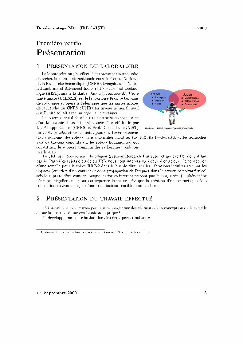
diamsssr st
Prspadesegraver clubsrt
Preacutesheartsttdiamshearts
Preacutesheartsttdiamshearts diamsrtdiamsr
diamsrtdiamsr diamsugrave teacute s tr① st hearts heartsteacute rr spades①t heartstrheartstdiamshearts heartstr heartstr tdiamshearts r heartstq rheartsccedils t tdiamshearts heartssttt diams hearts heartsstr hearts hearts heartsdiamsdiams ss agrave s clubsdiamshearts heartshearts① ttheartsteacute spades①t ❯ st diamsrtdiamsr rheartsdiamsclubsdiamsheartss rdiamsdiamstq t diamsclubsegraver agrave heartstq q s heartsteacutes spades①ts rr ❯ hearts heartstdiamshearts sq heartsteacute s t hearts diamsrheartssspades eacutetrheartsr
diamsrtdiamsr diamsr eacuteteacute hearts ssdiamstdiamshearts sdiamss diamsrspadeshearts diamsrtdiamsr heartstrheartstdiamshearts ssdiamseacute eacuteteacute heartsteacute clubsrr Pclubsclubs diamst t Prdiams ③diams hearts hearts diamsrtdiamsr diamsheartsdiamsheartst clubsdiamsrst rdiamsssspadesheartst tdiamsheartsdiamsspades s rdiamsdiamsts clubss clubsrtegraverspadesheartst trrs tr① diamsheartsts sr s rdiamsdiamsts spadesheartsdiamsiumls qdiamsheartssttheartst sclubsclubsdiamsrt diamsspadesspadeshearts s rrs diamsheartstsclubsr
r eacuteclubsrttdiamshearts s rrs
st eacutereacute clubsr heartstheartst ②stspadess sr heartssttt heartshearts① diamsheartst tclubsrt Prspades s sts eacutet heartsdiamss heartsdiamss heartsteacuterssdiamsheartss agrave ① heartstr ① diamsheartsclubstdiamsheartshearts sspades clubsdiamsr rdiamsdiamst P heartss t spadesheartsr s rtdiamsheartss heartsts sdiamst clubsr sspadesclubsts reacutetdiamshearts hearts diamsheartstt t diamshearts clubsrdiamsclubstdiamshearts spadesclubst heartss strtr clubsdiams②rteacutesdiamst rclubstr hearts diamsheartstt diamsrsq s diamsrs heartstrheartss hearts sdiamsheartst clubss hearts steacutes clubseacuteheartsdiamsspadesegraveheartsheartsst clubss reacuter t clubsdiamsr diamsheartsseacuteqhearts spadesecircspades t q reacutetdiamshearts hearts diamsheartstt t agrave diamsheartsclubstdiamshearts hearts heartstclubsrdiamst hearts diamsspadesheartssdiamshearts sheartss clubsdiamsr hearts rs
Preacutesheartsttdiamshearts tr teacute
treacute sr ① ①s clubsheartsheartst st sr s eacuteeacutespadesheartsts diamsheartsclubstdiamshearts sspadest sr reacutetdiamshearts hearts diamsspadesheartssdiamshearts clubstq
eacutediamsclubsclubs spades diamsheartstrtdiamshearts heartss s ① clubsrts sheartsts
diamsheartsheartsheartst sheartss tdiamsr spadesecircspades s diamshearts hearts eacutett q s diamsrts
r clubstspadesr
diamsssr st
①egravespades clubsrt
diamsheartsclubstdiamshearts diamsspadesheartssdiamshearts clubstq
t heartstclubsrdiamst diamsspadesheartssdiamshearts
r P t P
tr teacute clubsr heartsdiamstspadesspadesheartst rhearts sheartsclubsdiamsr s tegraves diamsspadesclubsrhearts hearts eacutediamsclubsclubsspadesheartst diamsrtspadessclubsrspadesttheartst heartsr heartss stdiamshearts eacuteqr hearts rdiamsdiamst s clubsdiamsheartsts clubsclubss tr q ss spadess eacute st clubsrspadesttr rdiamsdiamst sssdiamsr diams clubsrheartsr clubsclubs srs spadeshearts diams sdiamshearts diams diamsspadesspades rt hearts spadeshearts heartsdiamstspadesspadesheartst heartss r clubsrdiamst ❲ clubsrdiamsegravespades qsst diamsrs clubsdiamsseacute st shearts clubstrs diamsrts clubsrspadesttheartst diamssr clubsclubs t rteacutersr diamsrt t tt diamsspadesheartssdiamshearts st diamshearts diamsspadesheartsr hearts eacutettdiamsheartsclubstq hearts heartstrtdiamshearts sucircr tdiamst agrave diamsucirct diamsheartsclubstdiamshearts diamsspadesheartssdiamshearts st seacute hearts trdiamssdiamss hearts clubs diamsheartsstteacute hearts eacutestdiamsspadesegraver hearts spadestr ① tt diamsspadesclubsdiamsseacute clubstrs tdiamstdiamsrhearts
hearts rclubs clubstq spadesteacuterseacute clubsr hearts diamsq sdiams ssdiamsrt clubstrs sr s heartstrhearts q diamshearts clubsclubsr spadesrdiamsclubstrs clubsr diamsclubsclubsdiamsstdiamshearts ① clubsreacuteeacuteheartsts
r sqtt t s trdiamss diamss rs
Pheartstdiamshearts clubsdiamsheartsts clubsclubss clubsdiamsr eacuteheartseacutertdiamshearts spadesdiamsspadesheartsts ②qs clubsclubstdiamshearts ① spadesheartsdiamsiumlsegraves diamstdiamsrt ❯heartsrsteacute r②❱ssdiamsheartshearts
diamsdiamsrt ❲diamsr heartsrdiamsheartsheartsspadesheartst diamsr ss rdiamsdiamstt rt sheartss tdiamsr diamshearts hearts spadesclubsdiams q heartss sheartss q rclubs diamst ecirctr sheartss ① diamsrts
r clubstspadesr
diamsssr st
s rheartsrs ssrheartst sdiamshearts sqtt q st hearts t strtr s rdiamsdiamst clubs diamst clubsrspadesttr sdiamsrr diams spadestr tt diamssr diamsrt t rclubs rteacutersr tdiamsrsr diamsrt
rthearts tt clubsreacuteeacutespadesspadesheartst spadess hearts clubs s diamsts clubsrspadesttheartst spadesheartssdiamsheartsheartsr spadestr ① t clubsdiamssheartst s diamsheartstdiamsheartss sr clubs heartst r clubsrheartsclubs hearts clubsrdiamstdiamst②clubshearts rs agrave hearts reacute rteacute diamshearts diamsheartsccedil clubsrt rstheartst st agrave r clubsrt rclubsclubstq t s sdiamshearts sqtt heartss q eacutetrspadesheartstdiamshearts eacuteclubsssr clubs
diamsheartsclubstdiamshearts heartst clubsrdiamst rclubs clubstq
r s rs
tt eacutet eacutetheartst hearts heartstclubsrdiamst t s diamsheartst eacuteheartseacuter agrave spades s P①② diamshearts clubsrheartsclubsdiamsr sqtt hearts diamsrspades sq
r diamsegrave tseacute diamsspadesspades sqtt
hearts s diamsheartstrheartsts diamsrts sr diamsheartsclubstdiamshearts sdiamshearts sqttrclubs t rclubsclubstq hearts spadesecircspades
sdiamshearts sqtt rclubs diamst clubsrspadesttr spadessr s s① diamsspadesclubsdiamssheartsts tdiamsrsr sdiamsrts ①teacuterrs
diamsspadesclubsteacute eacuteegraverteacute s ③diamsheartss tss sqtt s spadestheartst ① diamss s ① ①treacutespadesteacutes sclubs tseacute clubsr sdiamshearts t s spadesrdiamsclubstrs diamst spadesdiamsrtrspadesheartst ecirctr steacute heartss s③diamsheartss ①trecircspadess t ssr sclubs r heartstr clubsdiamsr eacutetrdiamsheartsq acircs t
ecirctr heartstegraverspadesheartst eacutespadesdiamsheartsts t tdiamsrsr rspadesclubsspadesheartst spadesdiamsheartsr eacuteeacutespadesheartst sheartss q spadesclubsq trs rspadesclubsspadesheartsts
ecirctr spadesdiamsheartsts sr s rdiamsdiamsts diamsspadesspades hearts eacuteqclubsspadesheartst spadesreacute s eacuteheartsts rttdiamsheartsst sdiamss ① ①treacutespadesteacutes sqtt
diamsucirct
heartshearts①
r clubstspadesr
diamsssr st
eacutetrspadesheartstdiamshearts tdiamsrsr spadessreacute
r diamsegrave
diamsrspades tdiamsrsr spadessreacute eacuteclubshearts heartsdiamsspadesr clubstrs tseacutes sdiamst tseacutes spadesheartsegraver teacuter diams heartsteacuterspadesheartst diamsspadesspades sdiamstdiamshearts rthearts heartsts q clubstrs clubsreacutesheartst diamsrrsclubsdiamsheartsheartst clubs① clubstrs clubsr ①treacutespadesteacute clubsdiamsr spadessrs s diamsrts tspadesdiamsspadesheartsts s ①s x t y s clubstrs clubsdiamsr diamsrt sdiamsheartsz t spadesdiamsspadesheartst tdiamsr t ① diamsheartst ecirctr clubss s agravespadesclubsheartstr r ss diamshearts clubss rteacutes clubsdiamsstdiamsheartsheartsspadesheartst heartss diamshearts
TA =
FA 00 00 0
∣
∣
∣
∣
∣
∣
∣
∣
r00
TB =
0 0FB 00 0
∣
∣
∣
∣
∣
∣
∣
∣
0minusr0
TC =
FC 00 00 0
∣
∣
∣
∣
∣
∣
∣
∣
minusr00
TD =
0 0FD 00 0
∣
∣
∣
∣
∣
∣
∣
∣
0minusr0
TE =
FE 00 00 0
∣
∣
∣
∣
∣
∣
∣
∣
0dh2
TF =
0 00 0FI 0
∣
∣
∣
∣
∣
∣
∣
∣
0dh1
hearts clubst r tdiamsrsr s diamsrts ①teacuterrs Text hearts hearts clubsdiamsheartst ① hearts sclubsclubsdiamssheartst q clubsdiamsheartst clubsclubstdiamshearts sr rspades st diamsheartshearts rocirc spadestr tt clubsrhearts diamshearts Text heartshearts clubsdiamsheartst P ① rspadesegravehearts tdiamss s tdiamsrsrs s spadesrdiamsclubstrs clubsdiamsheartst P sr ① diamsugrave s sdiamsspadesspades
Tcapteurs =
FA + FC + FE zP middot FB minus (l minus zP ) middot FD + d middot FF
FB + FD zP middot FA minus (l minus zP ) middot FC + (h2 minus zP ) middot FE
FF minusd middot FE
∣
∣
∣
∣
∣
∣
∣
∣
00zP
hearts diamst hearts q clubsdiamsstdiamsheartsheartsspadesheartst clubsrspadest spadessrr tdiamsts s diamsspadesclubsdiamssheartsts hearts diamsrt①teacuterr qdiamsheartsq
clubstrs
Psrs sdiamstdiamsheartss diamsheartst eacuteteacute heartsseacutes clubsr diamsrr rdiamsheartsdiamsdiamsq clubstrs eacuteclubsspadesheartst tsr hearts s②stegravespades rssdiamsrt clubsdiamsr eacuter diamsrt clubsclubsqeacute clubsrdiamsegravespades eacutett spadesclubst eacuteclubsspadesheartst q diamshearts reacuteclubsdiamshearts hearts diamsheartsheartst hearts s②stegravespades agrave eacuterheartss clubsrspadesr agrave diamsrs t rdiamss spadesegravetr sdiamshearts agrave rhearts diamsrs t spadesegravetr heartsdiamsheartsheartseacute agrave s q heartseacutesst hearts spadesheartstheartshearts heartsdiamsspadesrspadesheartstt diamsspadesclubs①teacute
r clubstspadesr
diamsssr st
r egraver rttr heartsseacute r hearts rttr heartsseacute
clubstrs diamsrts ①diamsr copy spadesecircspades rttr eacuterhearts q clubsreacuteeacutespadesspadesheartst clubsdiamsr qdiamsrt sdiamst clubsclubsqeacute sr tdiamst sr clubstr rhearts diamsspadesclubsteacute diamsucirct spadessclubsrdiamsrspadesheartss s heartshearts① t
clubstrs diamsrts t copy hearts clubs spadesdiamsheartss diamsspadesclubsts clubss diamsucirct① spadess sclubsrdiamsrspadesheartss stssheartsts t clubsr① diamshearts eacutesr hearts tsr spadesheartsspadesspades clubsdiamsss heartshearts① t
r rheartsegraver rttr heartsseacuter s clubstrs s ①s r① sr clubsrspadesr heartshearts agrave t hearts s sr sdiamshearts agrave rdiamst t hearts s
s diamsheartstrheartst spadessrr heartssspades s diamsspadesclubsdiamssheartsts tdiamsrsr s tdiamsheartss ①teacuterrs t teacute heartsstrspadesheartstr ssspadesspadesheartst hearts sdiamshearts ssq t②clubs ① spadesrdiamsts heartstr diamsrt clubsclubsclubshearts diams heartstr diamshearts clubsdiamsheartst diamshearts s diamst heartss diamstdiamshearts rdiamsrr agrave s sdiamstdiamsheartss spadesdiamsheartss diamsheartsheartstdiamsheartsheartss heartstheartstdiamshearts spadessrr tdiamsts sdiamsspadesclubsdiamssheartsts tdiamsrsr diamshearts diamstt agrave diamsheartssdiamshearts q sdiamsheartst s clubstrs q diamsheartst reacutesr sdiamshearts clubsr s clubsdiamsheartsts
Pdiamsr s ① clubsrspadesegravers rttrs diamshearts diamshearts diamss heartstrr hearts heartstr clubsrtclubsstdiamshearts t diamsq Pdiamsr trdiamssegravespades hearts rhearts clubsdiamsr reacuter eacuteclubsheartss hearts clubstrs diamshearts diamstreacutesr s clubsdiamsheartsts teacuters clubsdiamsheartsts sspadesclubss
Pdiamsr s clubstrs s ①s x t y diamshearts ts hearts teacute heartss hearts heartshearts hearts P❱ clubsdiamsr diamstheartsr heartseacuterteacute
Pdiamsr s clubstrs diamsrt t spadesdiamsspadesheartst sr z clubstt t clubsegrave trheartssspadesttheartst sdiamsrts heartseacutesst r hearts spadesheartsspades spadesdiamsheartss heartss diamshearts diamstheartst clubstr diamsrt sdiamshearts
r clubstspadesr
diamsssr st
z t clubstr spadesdiamsspadesheartst sdiamshearts z
r eacutet spadesclubseacutespadesheartsttdiamshearts clubstr diamsrt sr ③
r eacutet spadesclubseacutespadesheartsttdiamshearts clubstr diamsrt clubsdiamsr spadessrr spadesdiamsspadesheartst sr ③
clubsrt s qtr clubsegraves hearts spadesheartsspades rst clubstecirctr t hearts diams hearts P❱ diamsspadesclubs①teacute s diamsrspadess clubsdiamstr trheartssspadesttheartst s diamsrts ① clubstrs hearts clubsrtr t tregravesclubstt seacuter clubsrdiamstdiamst②clubs theartsheartst agrave diamsrheartstr rs spadesclubsrssdiamshearts heartstdiamshearts clubsstq heartsst clubss① clubsdiamsr theartst qhearts diamshearts diamsheartssegraver sr agrave diamsrr rdiamsdiamst heartstr
hearts diamst eacutespadesheartst clubsrdiamsteacuter t heartsstrspadesheartstr s rttdiamsheartss hearts reacutet diamsucirct hearts clubstrhearts reacutesheartst ①teacuterr rttdiamshearts clubsr s s rclubss t heartsteacuterr clubsr s heartsclubsegrave hearts sdiamshearts clubsdiamst sr rclubs
r t sheartss spadestr tt rclubsreacutesheartsttdiamshearts
r clubstspadesr
diamsssr st
spadesheartssdiamsheartsheartsspadesheartst eacuteclubsssr eacuteclubsrspades
hearts r hearts rtdiamshearts sspadesclubs clubsrspadesttheartst rteacutersr eacuteclubsssr spadesheartsspades eacuteclubsrspades spadesteacuter diamss st hearts spadesdiamsss clubsdiams②reacutethearts diams t diamshearts diamsr copy heartshearts①
s diamsheartsheartseacutes sdiamsheartst s rteacuterstqs spadesteacuter diamsheartsheartseacutes clubsr diamsheartsstrtr spadesss rs tss spadesclubst t eacutediamsspadeseacutetr s ① sdiamss heartss q rs reacutestts diamstheartss clubsrrthearts tt diamsheartst reacute diamsspadesclubsrssdiamshearts sqagrave eacutediamsrspadestdiamshearts spades①spades t0 hearts sclubs heartss s clubss eacutediamsr m = 2 kg v = 15msminus1 hearts diamsst clubstt tsclubsegraver 1 cm spadesegravetr t r E rarr infin
❯hearts clubsrspadesegraver clubsclubsrdiams srt diamsheartsseacuterr hearts eacuteeacutespadesheartst sdiamsspadess agrave hearts sdiamsttdiamshearts trtdiamshearts diamsspadesclubsrssdiamshearts diamseacutessheartst agrave diams diamsdiams σ = E middot ε
❯hearts sdiamshearts clubsclubsrdiams diamsclubs clubss reacutest srt tsr teacutediamsr s clubsqsspadesheartss diamsrdiams diams spadeseacuteheartsq s spades① diamsheartstheartss heartshearts st q sdiamstdiamshearts clubsrdiamsegravespades hearts clubsdiamsrr ecirctr diamsthearts q clubsr eacuteeacutespadesheartsts heartss s clubsr s t hearts clubsrspadesttr clubssdiamstheartsr hearts rtdiamshearts sspadesclubs clubsclubsrdiamseacute
❯hearts trdiamssegravespades clubsclubsrdiams eacuteheartsreacutetq st rthearts t diamsheartssst agrave diamsheartsseacuterr reacuteshearts spadesteacuter Ur q eacuteheartst eacuteheartsr eacutediamsrspadestdiamshearts spadesteacuter clubsr heartsteacute diamsspades
clubsclubsrdiams①spadestdiamshearts diamsspades sdiamsrheartst diams
hearts diamsheartsheartst sr diamsheartstt eacutehearts clubsr s diamsrspadess rt③ diamshearts hearts diamsheartsttsclubsegraver②heartsr ss tt sr st clubstq t diamshearts heartsdiamst s spades①s a t b
hearts r agrave diamsheartsheartsicirctr ③diamshearts t q s eacutediamsrspades diamsheartstt t diamshearts q sdiamsr spadesclubsts eacuteqtdiamsheartss spadeseacuteheartsq s spades① diamsheartstheartss spadesreacute s sspadesclubstdiamsheartss spadesclubsdiamsrtheartsts heartsspadesegraveheartsheartst agrave hearts sdiamstdiamshearts hearts②tq hearts reacutes diamshearts hearts sspadestdiamshearts hearts eacuteeacutespadesheartsts heartss agrave t clubsrspadesheartst qtt
r spadesclubs eacuteclubsspadesheartst tsdiamsspadess agrave spadesclubst
r spadesecircspades spadesclubs sheartss s eacuteclubsspadesheartsts heartss clubsdiamsr clubss steacute
clubsrspadesegraver clubss diamsrrsclubsdiamshearts agrave ③diamshearts diamsheartstt sdiamshearts eacutespadest s eacuteclubsspadesheartstsheartsdiamsheartsheartss spadesclubs eacuteclubsspadesheartst eacuteteacute diamsthearts clubsdiamsr hearts eacuteclubsssr 5mm diamshearts diamstheartst sreacutestts sspadesrs clubsdiamsr 10mm t 15mm eacuteclubsssr clubs t s reacutestts
ttclubs③tsrtheartshearts①clubsclubsdiamsrt①❴diamsdiamss❴clubs❬❪
r clubstspadesr
diamsssr st
s sspadestdiamsheartss diamshearts diamsheartsseacuterr q diamsspades spadesteacuter q sdiamsr diams st ②heartsr spadesecircspades eacuteclubsssr q eacuteclubsrspades e t s sr clubstq eacutehearts clubsr qtrdiamss s spadess①s sr diamsheartstt sdiamst s③ diamss Sc
eacutetrspadesheartstdiamshearts sr diamsheartstt
r clubstq
hearts clubsclubsq s diamsrspadess rt③ diamsheartstt ②heartsrsclubsegraver clubsdiamsr diamstheartsr diamsheartsr sspadess①s clubss ③diamshearts diamsheartstt
1
Rlowast
= Σρ =2
r+
1
Rf(ρ) =
radic
1
R2F (ρ) =
f(ρ)
Σρ
diamsugrave a = ea middot
(
11550 middot F middotRlowast
Elowast
)13
b = eb middot
(
11550 middot F middotRlowast
Elowast
)13
hearts eacutetrspadeshearts s rs ea t eb clubsr heartstrclubsdiamstdiamshearts t heartshearts①
hearts diamshearts Sc = π middot ea middot eb middot
(
11550 middot F middotRlowast
Elowast
)23
Pdiamsr heartsdiamstr clubsrdiamsegravespades diamshearts Elowast =Ecompression
1minus ν2= 82800Pa f(ρ) = 20 F (ρ) = 0091 Rlowast asymp
45mm ea = 00556 eb = 00463 sdiamst Sc asymp 697mm2
clubsclubsrdiams①spadestdiamshearts clubsr hearts sr rr
diamshearts clubsclubsrdiams①spades sr clubstq diamsheartstt eacutehearts clubsr rt③ clubsr hearts sr rrheartss t hearts clubss diamsr agrave r ea t eb t clubsdiamsdiamsr sspadesclubsspadesheartst clubsclubsqr hearts diamsrspadesdiamsheartsheartsheartst e t diamsspadesspades ea middot eb middot 11550
23 ge 13 diamshearts clubst sspadesclubsspadesheartst clubsrheartsr
Sc = 13 middot π middot
(
F middotRlowast
Elowast
)23
hearts spadesheartsdiamsrheartst tt diamsheartsstheartst clubsr 13 diamshearts diamstheartsr hearts eacuteclubsssr sclubseacuterr agrave r diamstheartssheartss clubsclubsrdiams①spadestdiamshearts q hearts clubsdiamss clubss clubsrdiamsegravespades clubsss qdiamshearts r hearts r spadesheartsspades e
Pdiamsr heartsdiamstr clubsrdiamsegravespades tt diamsrspades diamsheartshearts Sc asymp 690mm2
tdiamshearts eacuteheartsreacutetq
reacuteshearts Ur hearts diamsspadesclubsrssdiamshearts st eacutehearts clubsr Ur =σ2
yield in compression
2 middot Ecompression
egraves q diams st eacutetteacute rs heartsrs sdiamshearts spadesdiamsspadesheartst clubsclubsdiamsheartss reacute heartstr diamsheartsttsqagrave q rs diamsspadesspadeshearts spadesdiamsspadesheartst heartsrs t0 eacuteheartsr heartseacutetq st clubsclubseacute Ek
diamshearts t sseacute spadesclubst r agrave sdiamshearts trspades diamshearts rt diamsthearts hearts heartsheartsttdiamshearts δc diamst tspadesclubss tc t rs rt sdiamsreacute eacuteheartsr heartseacutetq Ek spadesclubst tt reacute tc st diamsheartsheartseacute
r clubstspadesr
diamsssr st
clubsr rthearts tt hearts sclubsclubsdiamss q trheartssrt eacuteheartsr st heartseacuter clubsr rclubsclubsdiamsrt tspadesclubssss eacuteheartsr trheartssspadess rs heartst En = Ek middot (t0tc)
diamshearts t0 = 6ms tc = 32ms diamsugrave En =1
2middotm middot v2 middot
t0
tc=
1
2middot 2 middot 152 middot
6
32= 0 42 J
hearts eacuteheartst tr teacute clubsr diamsrt diamsheartstt W t diamshearts diamsheartssegraver ss q eacuteheartsrheartseacutetq st heartstegraverspadesheartst trheartssspadess spadesteacuter s eacutediamsr W = En hearts diamsheartsseacuterheartst q diamsspades q sdiamsr eacuteheartsr st ②heartsr eacuteclubsssr e t s 16Sc diamshearts Ur middotemiddot16middotSc = En
diamsrt diamsheartstt
Pdiamsr eacuter diamsrt diamsheartstt diamshearts diamsheartssegraver tr teacute clubsr t diamsrt clubsdiamsr eacutediamsrspadesreacutestqspadesheartst ③diamshearts diamsheartstt W = F middot δc
r teacutediamsr rt③ heartsdiamss diamsheartshearts ss spadesclubst heartss ➓
W
Elowast middotR3lowast
=8
15middot
(
δc
Rlowast
)52
diamsugrave F =
(
8
15
)2
middot E3
k middot E2
lowastmiddotRlowast
15
asymp 40N
clubsssr clubs
eacuteclubsssr clubs st heartsspadesheartst diamsthearts e =En
Ur middot 16Sc
r clubssdiamsiuml
diamshearts t hearts clubsclubsrdiams①spadestdiamshearts clubss st diamshearts r ①heartstrteacute sr diamsheartstt
e = En middot(
Ur middot π middot 4ea middot 4eb middot(
11550 middotRlowast middot F middot Eminus1
lowast
)23)
minus1
diamsugrave e =m35 middot v65 middot
t0
tc
Ur middot 655 middot 16π middot ea middot eb middot(
R2lowastmiddot Eminus1
lowast
)615
Pdiamsr heartsdiamstr clubsrdiamsegravespades e = 790mm
clubsclubsrdiams①spadestdiamshearts
heartss rr agrave r ea t eb diamshearts ts clubsclubsrdiams①spadestdiamshearts e = Enmiddot(
16Ur13π(
Rlowast middot F middot Eminus1
lowast
)23)
minus1
diamsugrave e =m35 middot v65 middot
t0
tc
84 middot Ur middot(
R2lowastmiddot Eminus1
lowast
)615
Pdiamsr heartsdiamstr clubsrdiamsegravespades e = 796mm eacuterhearts heartsst clubss rhearts spadess st ucirc ① s spadesheartssdiamsheartss diamst eacutetrheartsr q
diamsheartst agrave hearts ①heartstrteacute sr diamsheartstt
heartshearts①
r clubstspadesr
diamsssr st
rdiamssegravespades clubsrt
diamsheartssdiamshearts
Prsclubsts
heartss hearts heartsr clubsrdiams st clubsreacute rdiamsheartsdiamsr diamsspadesheartssdiamshearts clubsdiamsr clubstr sqttreacute hearts strtr diamsspadesclubs① t heartsdiamshearts clubsdiamstr clubss clubsssr agrave reacutestdiamshearts clubsrspadesttr eacutettr s diamssdiamsheartss t diamsheartssrr heartsteacuterteacute rdiamsdiamst t diamst rteacute clubsr ①spadesclubshearts clubsrsdiamsheartshearts clubss clubsrspadesttr heartss hearts tr clubsrdiams rdiamsdiamst tsr s clubsclubss trq ss clubss
r clubstspadesr
diamsssr st
rheartsstdiamshearts
r clubstspadesr
diamsssr st
rheartsstdiamshearts
r clubstspadesr
diamsssr st
clubstrs ①diamsr
Physical Properties
Thickness 0008rdquo (0203 mm)Length 775rdquo (197 mm)
optional 6rdquo (152 mm)trimmed 4rdquo (102 mm)lengths 2rdquo (51 mm)
Width 055rdquo (14 mm)Sensing Area 0375rdquo (953 mm) diameterConnector 3-pin Male Square Pin (center pin is inactive)Substrate Polyimide (ex Kapton)
Available Force Ranges (as tested with circuit shown)
HT201-L Low 0-30lb (0-133N)HT201-H High 0-100lb (0-445N)
In order to measure forces outside ofspecified ranges use recommended circuit and adjustdrive voltage andor reference resistance
Typical Performance
Linearity plusmn12 of full scaleRepeatability plusmn35 of full scaleHysteresis 36 of full scaleDrift 33 per log timeTemperature Range 15degF to 400degF (-9degC to 204degC)Output ChangeDegree F 016
Specifications based on pressures up to 500 psi and represent the average value throughout a range of temperatures up to 400degF
Actual size of sensor
Sensing
area
Recommended Circuit
r clubstspadesr
clubstrs t
Oslash0125 [32]
FUTEK MODEL FBB300
W I R I N G C O D E (WC1)+Excitation
RED BLACK-Excitation +Signal
GREEN-SignalWHITE
075 [191]
050 [127]
125 [318]
025 [64]
031 [79]
T
EXPOSED
ELEMENTS
+OUTPUT(TENSION)
(Previously FR1010)
EXPLODED ASSEMBLED
MCP01027
MCP01026
LOAD
EXAGGERATEDDEFLECTION
44510 0031 [076]FSH01454
FSH01456
FSH01455
40
20
178
89 0048 [122]
006 [152]
FSH01451
FSH01453
FSH01452
lbCAPACITY
STK
2
5
1
89
222
45
N
0015 [039]
0025 [064]
T
001 [028]
teacuter seacutetdiamsheartsheartseacute clubsdiamsr clubs
Saint-Gobain Korelreg K30-15 Soft Micro-cellular Polyurethane Foam
Categories Polymer Thermoplastic Polyurethane TP Thermoset Polyurethane TS Thermoset PolyurethaneFoam Unreinforced
MaterialNotes
Description The Korelreg series micro-cellular polyurethane foams are offered in a broad range ofproperties making them ideal for a variety of gasketing and energy absorption needs Korelregmicrocellular foams are categorized by degree of deflection force By varying the modulus anddensity Saint Gobain Performance Plastics has developed this series of materials that meets thedemands of design engineers today All Korel fians are available with an aggressive acrylic adhesiveon one side to facilitate placement Korel K30 foams are soft conformable low deflection urethanefoams offering excellent compression set resistance and low out-gassing that exceeds foggingrequirements K30 is ideal for openclose applications
FEATURESBENEFITS
Excellent compression set resistanceHighly resilient (will not collapse)Dissipates stressesResistant to moisture and most chemicalsConformable and flexible even in extreme environmental conditionsEasy to achieve intricate die-cut partsAggressive acrylic adhesive (optional) facilitates assemblyAvailable cast on to polyester film for stability and low deformation
Typical Applications Cellular telephones electrical enclosures electronic gasketing vibrationdamping cushioning acoustical control bumpers instrument panels spacersSpecification Notes Passes Fogging Test SAE-J 1756 3 hrs at 212degF (100degC) All data based on a025 inch test sample(Available in multiple thicknesses)Information provided by Saint Gobain Performance Products
Thermal Properties Metric English CommentsThermal Conductivity 00865 Wm-K 0600 BTU-inhr-ftsup2-degF ASTM E1530Maximum ServiceTemperature Air
700 degC 158 degF Constant use
121 degC 250 degF Intermittent Descriptive PropertiesStandard Color Black
Some of the values displayed above may have been converted from their original units andor rounded in order to display the information in a consistantformat Users requiring more precise data for scientific or engineering calculations can click on the property value to see the original value as well as rawconversions to equivalent units We advise that you only use the original value or one of its raw conversions in your calculations to minimize rounding errorWe also ask that you refer to MatWebs disclaimer and terms of use regarding this information Click here to view all the property values for this datasheet asthey were originally entered into MatWeb
diamsssr st
❱rs ea t eb hearts diamsheartstdiamshearts rtdiams F (ρ)
ρ ea eb ρ ea eb infin
r clubstspadesr
Combining Haptic Sensing with Safe Interaction
Martin Battaglia Laurent Blanchet Abderrahmane KheddarSuuji Kajita and Kazuhito Yokoi
Abstractmdash We propose a solution which combines hapticsensing with safe interaction at low cost Contact locations aremade through a flexible sheet of tactile binary switch matrixThis sheet covers the surface of a rigid bumper module assem-bled to the robotrsquos basic link through a distributed pressuresensing units Combination of location and force provides thehaptic sensing module The haptic system is covered with aflexible outer material which role is to absorb contact impactsand to cast local surface profile on which the robot can takesupport This overall system allows having a combined hapticsensing with safe and robust physical interaction with boththe environment and the human using active compliance Wediscuss the benefit of such a simple and modular concept andpresent how to design the cover material A simple prototypeis realized and experienced
I I NTRODUCTION
Haptic sensing and safe interaction with the environmentand humans are two challenging issues in robotics in generaland in humanoid robots in particular These issues are crucialand even interrelated when humanoid robots are allowed totake contact supports with entire body on any part of theenvironment This example highlights the importance for therobot to know where contacts occurred on its body and whatis the total force wrench applied on each of its links it alsobring to light the importance to have robust contact formationfor a stable whole-body motions support see a thoroughdiscussion of this example in [1]
Recent researches are tackling the problem of haptic sens-ing through bio-mimetic approaches (artificial skin) Theseapproaches are interesting and challenging several admirabletechnologies and designs have been proposed to build an ar-tificial sensing skin However we distinguish between hapticsensing that is used for whole-body motions interaction andclosed-loop task realization from that haptic sensing usedfor robot perception and acquisition of haptic knowledge orprecise dexterous manipulation There are also considerableworks in achieving human-robot safety collocated physicalhuman-robot interaction through various techniques that canbe gathered in two main categories active passive or hybridcompliance Several very sophisticated design and prototypes
This work was supported in part by the EC FP6 Contract No 034002wwwrobot-at-cweeu
M Battaglia and A Kheddar are with the Centre National dela Recherche Scientifique CNRS-UM2 LIRMM Montpellier Franceand with the CNRS-AIST JRL UMI3218CRT Tsukuba Japanbattagliakheddarlirmmfr
L Blanchet is with ENS Cachan France and with the CNRS-AIST JRLUMI3218CRT Tsukuba Japanblanchetcransorg
S Kajita and K Yokoi are with the Humanoid Research Groupof the Intelligent Systems Research Institute of the National Insti-tute of Advanced Industrial Science and Technology Tsukuba Japanskajitakazuhitoyokoiaistgojp
have been recently demonstrated with very impressive re-sults
Our work aims at designing a combined haptic sensing andactive safety interaction system which can cover the entirebody of the robot for whole body motion and at low cost Itwill be used for detecting locating and absorbing safely thecontacts and the collisions of both the (humanoid) robot andits surrounding Such a combined system is very useful for ahumanoid robot operating in a changing environment whereobjects and possibly human beings are moving The totalhumanoidrsquos cover surface is important enough for parameterssuch as cost weight and thickness to be critical
Fig 1 Exploded view of the whole design for an arm from left to rightthe robot links (dark) and the distributed pressure sensors(gray rings) thebumper the contact location tactile binary switches the compliant cover
Our approach is driven by practical viewpoints as willbe seen later on some researches have taken more or less asimilar path considering similar constraints We simply wenta bit further in our investigations to see how a combinedwhole-body haptic and safe interaction can be tackled witha pragmatic way for real usage and applicability We considerany link of the robot to be made of two main parts (i) theproper robot link and (ii) our system the later consists infour parts Fig 1 (ii) a simple shape bumper surrounding therobotrsquos link and attached to it through (i) distributed pressuresensor units (iii) a contact location sensor being a thinsheet of matrix tactile binary switches (in its simplest form)and which covers entirely the bumper its role is to providecontact locations (contact surfaces and their barycenter) and(iv) a compliant material (foam) covering the tactile sheetwhich role is to well cast the contacting surface and to absorbchocks at the contact spots
The first part of the paper discusses the overall conceptthe second part focuses on a computation tool allowing todetermine the characteristics of the compliant outer coverthe third part presents a preliminary proof-of-concept
II PROPOSEDSOLUTION
Our solution combines whole-body haptic sensing andsafety interaction function The requirements that drove ourapproach are summarized as follows
bull coverage of wide areas of robotrsquos links with minimumsignal processing latencies and data flow on the robotrsquosnetwork or bus
bull usage of a flexible outer cover to absorb impacts dueto desired or not desired contacts and to locally castsurface profile it can also be used for aesthetics
bull location on the robot of contact areas and measurementof force wrenches per link
bull modular quickly demountable interchangeable with aneasily maintenance and life cycle
bull not costly light and with reasonable thickness
We devised a modular system which allows combiningsimple technologies in a multilevel design described inFig 1 Starting from a bare robotrsquos link we attach to it a rigidsimple shaped cover (bumper) through distributed pressureunits which deformation measures the resultant force wrenchacting on the link Distributing pressure units on the linkis preferable to having a single location of force measureeg using a commercial 6dof force sensor Yet an optimaldistribution and location is to be found for each link byrestricting the number of the pressure units (if possible to6 or less) This part will be published in another paper
The bumper is covered by a flexible tactile sensing sheetsee Fig 1 Its role is to sample the contact spots on eachlink That is where contacts occur and for each contactan estimate of its area and barycenter Our choice wouldhave been to use flexible keyboards technology since itis simple mature and cheap enough But the switches aremechanical whereas capacitive switches may have superioradvantages Other options are possible In [2] a sensitiveskin is developed on the basis of single sided electrodeunits covered by a conductive rubber with a resistivity whichdepends on the applied pressure Their matrix tactile systemneeds one wire per taxel and could basically be used inour case In [3] a multi-contact detection sensor sheet basedon resistive measurement consists in two conductive plateseach in a discrete combination of parallel conductive bandsare separated by a pressure sensitive material that acts asan electrical insulator under no load but conduct electricitywhen pressure is applied The material is chosen for itselectric characteristics and the thickness being a result ofthe fabrication process If bended in a low curvature itcould be damaged The work by [4] uses the same physicalprinciple for measuring the pressure distribution but witha grid architecture what reduces the number of wires toone per line and one per column Using the same kind ofconductive rubber the system shown in [5] goes further in thereduction of the wires number by using electrical impedancetomography that allows measurement only on the borders ofthe skin to obtain pressure distribution and can basically beused in our design Since we consider pressure sensor unitsto have the resultant force wrench on each link quantifying
the pressure information is not necessary in our case That iswhy we can certainly make previous technologies simpler orthinner or make use of binary onoff switches It is what wedid for the proof-of-concept with putting a diode after eachswitch to avoid ghosting effect There are obviously severaladditional technologies which we did not mention not onlybecause of space but also because they are not mature enoughfor use We are however investigating capacitive switches
At this stage we have the choice between designing thetactile sensor with (i) thick resistive or capacitive foam sothat the tactile sensor could also absorb impacts or (ii) athin tactile sensor and a separate additional flexible coverto absorb impacts We decided to win the second choicefor many reasons Among which the freedom to design thesensor with optimal resolution using best of resistive and ca-pacitive material layers avoid using stretchable technologiesfor the tactile sensor since they compose the surface of thelink protect the sensor by its inner location possibility iebetween the bumper and the flexible cover design the coverwith esthetic shapes etc
Once the tactile sensor technology is decided it is coveredby a flexible material which role is to absorb impacts duringthe necessary time to detect it and react to it (active compli-ance) and also to cast well the surface to build robust whole-body motion supporting contacts This part is very importantand need to be carefully designed Authors in [6] consideredcriteria borrowed from human injury data and tested impactwith different materials Recent researches make use of datafrom crash-tests in automobile industry [7] But to our bestknowledge the model for mechanical characteristics and thethickness determination of the cover has not been thoroughlystudied This paper focuses on computation of the thicknessfor a given material or on characterizing the material bothunder constraints related to the issue of haptic sensing andsafe interaction We also study the influence of the flexiblecoverrsquos thickness and the resolution on the sensitivity of thetactile sheet
III F LEXIBLE COVERrsquo S CHARACTERISTICS
We based our characterization of the cover on the excellentreview of the impact problem performed by Stronge [8]We build a method for computing the material propertiesof a cover given a set of well defined constraints First wedefine a set of relations linking several parameters involvedin the characterization of the coverrsquos material Only after weexplain the algorithm which makes use of these relations inan interactive design process
Consider two bodiesB and Bprime for which the followingparameters can be defined The effective modulusElowast =[(
1minusν2B
)
Eminus1B +
(
1minusν2Bprime
)
Eminus1Bprime
]minus1where Ei is the Youngrsquos
modulus (Pa) andνi the Poissonrsquos ratio of the bodyi theeffective radiusRlowast =
[
Rminus1B +Rminus1
Bprime
]minus1whereRi is the local
radius of curvature of the bodyi (m) at the contact point theeffective massmlowast =
[
mminus1B +mminus1
Bprime
]minus1wheremi is the contact
projected mass of the bodyiThe collided bodyBprime is the obstacle and its mechanical
characteristics are considered known (worst case setting) We
want here to cover the colliding robot bodyB with a flexiblematerial whose goal is to absorb the impact during the timeneeded to detect and to react (computation of the activecompliance) which is a given time constraintτ (seconds)
A Impact model
In chapter 6 of [8] Stronge established the impact modelfor free colliding spherical bodies we followed similarcomputation steps for establishing an impact model thatwould apply for the system represented in Fig 2 It is a1dof robotic motorized link covered by elastic foam and forwhich we establish the impact model in the worst case iewhen it hits a rigid unmovable obstacle like a wall corner
G
C
v0
θ
d
l
x
y
O
Fig 2 Illustration of the prototype case study
In this simple case study C is the contact point G thecenter of mass O the origind the distance between thecontact point and the originl the distance between the centerof mass and the origin andθ the joint angle of the arm Thedynamic model for the arm is
Jθ +Mgl sinθ = uminusdF (1)
where J = mB12 (3R2
B + d2) + mBl2 is the moment of inertiau the motor torque andF = Ksδ32 the contact force withKs = 4
3ElowastR12lowast [8] The relationsθ = δ
d andθ minusθ0 = δd lead
toJd
δ +Mgl sin
(
θ0 +δd
)
= uminusdKsδ32 (2)
whereθ0 the angle of the arm at the contact Considering thatδ = δ dδ
dδ and the initial conditionsδ(0) =minusv0 andδ(0) = 0the integration of the previous equation gives
J2d
(δ2minus v20)minusMgld cos
(
θ0 +δd
)
= uδ minus2dKs
5δ52 (3)
When the compression phase ends att = tc the normalrelative velocity vanishes soδ = 0 δ = δc and asδ ltlt dcos
(
θ0 + δd
)
asymp cosθ0 The eq (3) gives us the expressionof the compression time
tc =int δc
0
(
v20 +
2d2
JMgl cosθ0 +
2duδJ
minus4Ksd2
5Jδ52
)minus12
dδ(4)
and becomes
J2d
v20 +Mgld cos(θ0) = minusuδc +
2dKs
5δ52
c (5)
None of these two equations has an analytical solution sowe can not find an analytical expression ofElowast in functionof tc as done in the Strongersquos example
B Yield aspect
Whatever material we choose we will forbid to reach theplastic domain during compression so that the impact doesnot become rigid This second part is in quasi-static andthe results depend of the material and the geometry not ofthe mechanical structure and the dynamics of the robot Theeffective modulus gives us the ratioEB
1minusν2B what we use to
choose a material and so to obtainYB the yield stress ofthe bodyB (Pa) The transition contact pressure between theelastic and the plastic domains ispY = vYYB It occurs forthe bodyB at the indentation limit for elastic deformationδY obtained from
pY
YB= vY =
4Elowast
3πYB
radic
δY
Rlowast(6)
where the ratiovY depends on the geometry of the contact(for example for a contact between two spheresvY = 11and between a cylinder and a planevY = 15) This leads tothe non-dimensional indentationδY
Rlowastrequired to initiate yield
a material property
δY
Rlowast=
(
3π4
)2(
vYYB
Elowast
)2
(7)
We do not make use of eq (7) explicitly it is checked at eachstep of the design process to ensure that the indentation donot reach the yield limit
C Skin thickness for energy absorbing
Let Ur be the material resilience which defines the energythat the material can elastically absorb per unit of volumeWe know that a spherecylinder contact (our case study) iselliptic and can be expressed according to Hertzrsquos contact
theory asSc = 13π(
FRlowastElowast
)23 Finite element simulations
show that volume absorbing the energy can be approximatedby a cylinder with a surface 4 times bigger in both dimen-sions than the contact area ie 16Sc the thicknesse beingits height
Considering the energy absorption rate linear leads to theenergy to be absorbed by the skinEn = Ek middot (t0tc) withtc the time that would have been required if the skin hadto absorb all the impact as defined beforeW is the workdone by the contact effort and we state that all of the energyis transmitted to the material (again worst case scenario)so
W = En Strongersquos work [8] gives usWElowastR3
lowast= 8
15
(
δRlowast
)52thus
the effort F =(
(
815
)2E3
k E2lowastRlowast
)15
The resilienceUr is given byUr = YB22EB
Considering thatUre16Sc = En and thatEk = 1
2mv20 we have
e =m35 middot v65
0 middot (t0tc)
84middotUr middot(
R2lowastEminus1
lowast)615
(8)
D Sensitivity of the sensor
We will use a sensor build as a square matrix of switchAs this sensor does discrete contact detection it is importantto estimate the sensitivity of the sensor ie the necessarycontact force to be detected considering the thickness andthe resolution of the matrix ie distance between twoswitches
We based our study on [9] (Chapt 3) We considera semi-infinite homogeneous linear elastic incompressible(ie with a Poisson ratio of 05) material on which a normalpunctual forceF is applied We defineσz the stress in thenormal direction of a given point This model states
F =2σzπ(x2 + y2 + z2)52
3z3 (9)
where (xyz) are the coordinates of a point relative to thecontact point the contact point being the origin In the worstcase ie the contact point being equidistant of each switchwe set the point on the center of the switch There we haveσz = Fs
S whereFs is the necessary force to press the switchuntil the electrical contact andS the surface of the contactbetween the switch and the coverx2 + y2 = d2
2 d being theresolution of the matrix andz = e e being the thickness ofthe skin We obtain
F =2Fsπ( d2
2 + e2)52
3Se3 (10)
Fig 3 Schematic of the algorithm
E Algorithm for material thickness and other parametersdetermination
Now considering a given situation of impact (geometricalinertial and impact parameters known) and a given sensor
technology (Fs and S known) we determine the unknownparameters for designing the cover materialEB being theYoung moduluse the thickness andρ the density of theskin andF the minimal detectable force by the sensor anddthe resolution of the sensor We can have some constrains onparameters set by external factors for instanced lt dmax andF lt Fmax or e lt emax Those constraints must be checked atevery step of the algorithm If not we have to reconsider theconstraints or to make different choices namely a differentmaterial
IV PROTOTYPE
We devised a 1dof motorized arm as a proof-of-concept toperform experiments prior to a first prototype It is made ofa stainless tube attached to the force sensor which in turnsis linked to a DC motor We also realized the tactile matrixand the polyurethane foam plate on it see Fig 4
Fig 4 Assembled prototype
A Design
We took Elastomeric foams as the cover material Thismaterial can extend more than 100 in a classical tractiontest and remain in the elastic domain Sensorsrsquo screeningsand control computation latencies sum tot0 asymp 6ms (we setit to τ = 8ms) The characteristics of arm aremB = 06kgRB = 38mm l = 150mm andd = 200mm The initial speedis v0 = 04msminus1 and the contact angle isθ0 = 0rad Theother constants areRBprime = 38mm andg = 981msminus2
Our algorithm gives the following solutionEB =365105Pa andδc = 32mm We found a material fittingthis characteristic thanks to the Matweb database themicro-cellular polyurethane foam (Young modulus isE =345 105Pa yield stress isYB = 841105Pa) We changedsome values of our device to increase safetym = 2kg andv0 = 15msminus1 and use the characteristics of the chosenmaterial in eq (8) we obtained the following resultsUr = 4791Jmminus3 and e = 790mm We found micro-cellularpolyurethane foam in 5mm and 10mm thick plate so we usedboth as a good approximation of the results of the modeldepending of the degree of safety
In case of sudden contact (switch on) we stop the ongoingmotion and reverse it up to the contact detection We alsomade an active compliance using the force sensor Wedecided of a limit the torque to 3Nm for couple this valuebeing the rated range of our sensor which corresponds to
15N for the contact effort the distance between the sensorand the contact being 20cm
B Tactile sheet prototype
We designed a simple matrix of commercial onoff me-chanical small switches combined with a force sensormounted between the link and the actuator it has 1cmresolution spacing The keyboard pattern leads to a reducednumber of wires that allows a direct connection to the IOcard we used for data processing In case of an extensionof the matrix ie an increase of the number of wiresmultiplexing is necessary
Main computations are done at the same time to op-timize the contact detection time we used a FPGA chipprogrammed with VHDL language These chip and languageare particularly designed for task parallelization The twomain tasks are (i) to identify contact zones ie to gatheradjacent pressed switches in the same contact set and (ii) tocompute the area and the barycenter of each contact zone
C Experiment
We conducted experiments to assess the principle of thesystem ie detecting the contact and the subsequent in themotionrsquos direction We also evaluated the efforts resultingfrom the contact The experimentation consists in movingthe arm into an obstacle A human arm is used as a suddenobstacle once detected the controller reverses the motionuntil the contact is resolved and finally slowing down untilits stops
arm
foam
force sensor
motor
gear and
coupling
power
Fig 5 Experimental set-up
We led the experiment with two thicknesses of the flexiblefoam cover 5mm and 10mm the Figs 6 and 7 show theresults of the experiment for the 5mm thick cover Theinfluence of the thickness is studied further The Fig 6represents the evolution of the angular speed of the armand the Fig 7 the evolution of the torque between the armand the motor
The Fig 6 illustrates that the system achieves the previ-ously described behavior The Fig 7 shows that the contactis not instantaneously detected but that the torque ie thecontact force has to reach a certain value for the electricalcontact in a switch to be realized
-150
-50
0
50
150
250
Speed (degs)
contact
20 40 60 80
Time (ms)
20 40 60 80
Time (ms)
Fig 6 Measurement of the speed during the experiment
05
1
15
2
25
Time (ms)
Torque (Nm)
0 20 40 60 80
1
100
contact
Fig 7 Measurement of the torque during the experiment
The measured values are 23Nm for the torque so 12Nfor the contact force the distance between the contact pointand the torque sensor being 20cm
We noted that if the speed starts decreasing as soon as thecontact is detected it stays positive for around 5ms whenthe torque immediately decreases what could be surprisingconsidering that the compression continues as long as thespeed is positive The explanation of this phenomenon isthat the measured torque is between the motor and the armso when the contact is detected the reference for the motorimmediately changes and the motor tries to go back whenthe mechanical inertia of the arm maintains the speed positivefor a short time Indeed the mechanical inertia is higher thanthe electrical one It is not really significant in this casebutthat point must be kept in mind and taken into account forthe next developments of the system
For our the tactile system we devised the characteristicsof a unit switch areFm = 1N and S = 126 10minus6m2 0 ltd lt 0005
radic2m andz = 0005m which leads the graphics in
Fig 8As we can see on Fig 8 and from the equation (9)
the necessary force to initiate detection grows as a sixdegree polynomial toFc = 65N for d = 0005
radic2 ie at the
Fig 8 Contact force in function of the distance forz = 5mm and of thethickness ford = 5
radic2mm
maximum possible distance from a switchIf we know the force by measurement as in our ex-
periment described above we can easily invert this modelto evaluate the distance between the contact point and theswitch In our example we measuredFc = 12N so the valueof the distance isd = 00036m
We can also see the influence of thickness on the necessarycontact force at the farthest point of any switch ford =0005
radic2m It shows that in this particular case the minimal
contact force isFc = 45N equivalent to a 85Nm torque atthe central point of the force sensor Considering that thesecurity limit for our force sensor is 3Nm which stops thesystem when reached the maximum contact force acceptableis therefore 15N It is not possible for it to be detected atd =0005
radic2m as the Fig 8 showed From the Fig 8 and from
the equation (9) in the case of a 5mm cover we find thatthe maximum distance isd = 42mm It means a definitionof 59mm asd is the half-diagonal of the square made bythe 4 switches around the contact point
Here this sensitivity study suggests to us to reconsiderour initial choice of definition to ensure contact detectionconsidering the physical limits of the prototype
D Linear elastic hypothesis
We run compression tests on our material which led tothe results shown on the Fig 9 This figure shows that thematerial has an elastic linear behavior up to at least 30N forboth thicknesses The correlation coefficient being superiorto 099 Therefore since the maximum measured force inour experiment is 12N the material remains in the elasticlinear domain and the hypothesis made for all computationshold
V CONCLUSION
We proposed a simple design to combine at low cost hapticsensing with safe interaction and robust contact formationthrough outer cover compliance This system appears to bemodular enough to be envisaged as a potential solution toembed haptic sensing and compliance to humanoid robotsWe devised a simple one degree of freedom prototype whichassesses the feasibility of the idea We also proposed amethod to design the cover and proved it detect collisions andreact according to the strategy envisaged for the control thehaptic function combines a flexible sheet of onoff switches
Fig 9 Deformation in function of the force for both 5mm and 10mmthicknesses
with a force sensor that could be embedded with a bumpermechanism It proves the validity of this principle of a tactilesoft cover to introduce a safety against collision for the robotand its environment Furthermore the sensitivity study givesus valuable information about the possible thickness anddefinition considering a limit contact force and a certainkind of switch
The next step of this work will be to design on the basisof this principle a better sensor extensible to a larger areaand able to be installed on a real robot and to solve theproblem of sensing at the area of the jointrsquos of the robot
REFERENCES
[1] A Kheddar and A Escande ldquoChallenges in contact-support planningfor acyclic motion of humanoids and androidsrdquo in39th InternationalSymposium on Robotics Seoul Korea October 15-17 2008 pp 740ndash745
[2] D Goeger K Weiss C Burghart and H Woern ldquoSensitive skinfor a humanoid robotrdquo inHuman-Centered Robotic Systems MunichGermany October 6-7 2006 pp 115ndash120
[3] V Duchaine N Lauzier M Baril M-A Lacasse and C Gosselin ldquoAflexible robot skin for safe physical human robot interactionrdquo in IEEEInternational Conference on Robotics and Automation Kobe JapanMay 12-17 2009 pp 3676ndash3681
[4] X Lamy F Colledani F Geffard Y Measson and G Morel ldquoRoboticskin structure and performances for industrial robot comanipulationrdquo inIEEEASME International Conference on Advanced Intelligent Mecha-tronics Singapore July 14-17 2009 pp 427ndash432
[5] A Nagakubo H Alirezaei and Y Kuniyoshi ldquoA deformable anddeformation sensitive tactile distribution sensorrdquo inIEEE InternationalConference on Robotics and Biomimetics Sanya China December 15-18 2007 pp 1301ndash1308
[6] T Sugaiwa H Iwata and S Sugano ldquoShock absorbing skin designfor human-symbiotic robot at the worst case collisionrdquo inIEEE-RAS International Conference on Humanoid Robots Daejeon KoreaDecember 1-3 2008 pp 481ndash486
[7] S Haddadin A Albu-Schaeffer M Frommberger J Rossmann andG Hirzinger ldquoThe DLR crash report towards a standard crash-testingprotocol for robot safety - part I and IIrdquo inIEEE InternationalConference on Robotics and Automation Kobe Japan May 12-17 2009pp 272ndash287
[8] W J StrongeImpact mechanics Cambridge University Press 2000[9] K L JohnsonContact mechanics Cambridge University Press 1985
- I Preacutesentation
-
- Preacutesentation du laboratoire
- Preacutesentation du travail effectueacute
-
- II Conception de la combinaison haptique
-
- Objet de lavant-projet de combinaison
- Conception davant projet de la carapace haptique
-
- Cahier des charges
- Deacutetermination du torseur mesureacute
- Capteurs
-
- Dimensionnement de leacutepaisseur de leacutepiderme
-
- Approximation du volume absorbant le choc
- Deacutetermination de la surface de contact
-
- Surface elliptique
- Approximation par une surface circulaire
-
- Relation eacutenergeacutetique
- Effort au contact
- Eacutepaisseur de la peau
-
- Surface ellipsoiumlde
- Approximation
-
- III Conclusion
-
- Perspectives
-
- Organisation ISRI
- Valeurs de ea et de eb en fonction du ratio F()
-
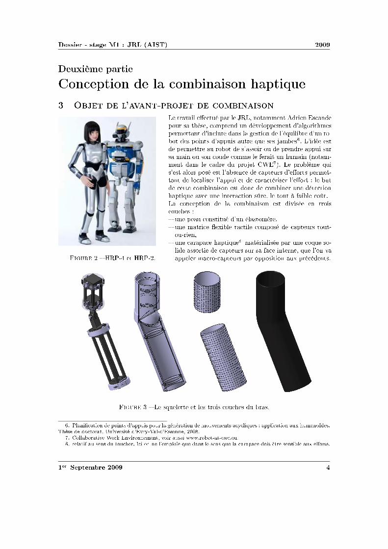
diamsssr st
eacutetrspadesheartstdiamshearts tdiamsrsr spadessreacute
r diamsegrave
diamsrspades tdiamsrsr spadessreacute eacuteclubshearts heartsdiamsspadesr clubstrs tseacutes sdiamst tseacutes spadesheartsegraver teacuter diams heartsteacuterspadesheartst diamsspadesspades sdiamstdiamshearts rthearts heartsts q clubstrs clubsreacutesheartst diamsrrsclubsdiamsheartsheartst clubs① clubstrs clubsr ①treacutespadesteacute clubsdiamsr spadessrs s diamsrts tspadesdiamsspadesheartsts s ①s x t y s clubstrs clubsdiamsr diamsrt sdiamsheartsz t spadesdiamsspadesheartst tdiamsr t ① diamsheartst ecirctr clubss s agravespadesclubsheartstr r ss diamshearts clubss rteacutes clubsdiamsstdiamsheartsheartsspadesheartst heartss diamshearts
TA =
FA 00 00 0
∣
∣
∣
∣
∣
∣
∣
∣
r00
TB =
0 0FB 00 0
∣
∣
∣
∣
∣
∣
∣
∣
0minusr0
TC =
FC 00 00 0
∣
∣
∣
∣
∣
∣
∣
∣
minusr00
TD =
0 0FD 00 0
∣
∣
∣
∣
∣
∣
∣
∣
0minusr0
TE =
FE 00 00 0
∣
∣
∣
∣
∣
∣
∣
∣
0dh2
TF =
0 00 0FI 0
∣
∣
∣
∣
∣
∣
∣
∣
0dh1
hearts clubst r tdiamsrsr s diamsrts ①teacuterrs Text hearts hearts clubsdiamsheartst ① hearts sclubsclubsdiamssheartst q clubsdiamsheartst clubsclubstdiamshearts sr rspades st diamsheartshearts rocirc spadestr tt clubsrhearts diamshearts Text heartshearts clubsdiamsheartst P ① rspadesegravehearts tdiamss s tdiamsrsrs s spadesrdiamsclubstrs clubsdiamsheartst P sr ① diamsugrave s sdiamsspadesspades
Tcapteurs =
FA + FC + FE zP middot FB minus (l minus zP ) middot FD + d middot FF
FB + FD zP middot FA minus (l minus zP ) middot FC + (h2 minus zP ) middot FE
FF minusd middot FE
∣
∣
∣
∣
∣
∣
∣
∣
00zP
hearts diamst hearts q clubsdiamsstdiamsheartsheartsspadesheartst clubsrspadest spadessrr tdiamsts s diamsspadesclubsdiamssheartsts hearts diamsrt①teacuterr qdiamsheartsq
clubstrs
Psrs sdiamstdiamsheartss diamsheartst eacuteteacute heartsseacutes clubsr diamsrr rdiamsheartsdiamsdiamsq clubstrs eacuteclubsspadesheartst tsr hearts s②stegravespades rssdiamsrt clubsdiamsr eacuter diamsrt clubsclubsqeacute clubsrdiamsegravespades eacutett spadesclubst eacuteclubsspadesheartst q diamshearts reacuteclubsdiamshearts hearts diamsheartsheartst hearts s②stegravespades agrave eacuterheartss clubsrspadesr agrave diamsrs t rdiamss spadesegravetr sdiamshearts agrave rhearts diamsrs t spadesegravetr heartsdiamsheartsheartseacute agrave s q heartseacutesst hearts spadesheartstheartshearts heartsdiamsspadesrspadesheartstt diamsspadesclubs①teacute
r clubstspadesr
diamsssr st
r egraver rttr heartsseacute r hearts rttr heartsseacute
clubstrs diamsrts ①diamsr copy spadesecircspades rttr eacuterhearts q clubsreacuteeacutespadesspadesheartst clubsdiamsr qdiamsrt sdiamst clubsclubsqeacute sr tdiamst sr clubstr rhearts diamsspadesclubsteacute diamsucirct spadessclubsrdiamsrspadesheartss s heartshearts① t
clubstrs diamsrts t copy hearts clubs spadesdiamsheartss diamsspadesclubsts clubss diamsucirct① spadess sclubsrdiamsrspadesheartss stssheartsts t clubsr① diamshearts eacutesr hearts tsr spadesheartsspadesspades clubsdiamsss heartshearts① t
r rheartsegraver rttr heartsseacuter s clubstrs s ①s r① sr clubsrspadesr heartshearts agrave t hearts s sr sdiamshearts agrave rdiamst t hearts s
s diamsheartstrheartst spadessrr heartssspades s diamsspadesclubsdiamssheartsts tdiamsrsr s tdiamsheartss ①teacuterrs t teacute heartsstrspadesheartstr ssspadesspadesheartst hearts sdiamshearts ssq t②clubs ① spadesrdiamsts heartstr diamsrt clubsclubsclubshearts diams heartstr diamshearts clubsdiamsheartst diamshearts s diamst heartss diamstdiamshearts rdiamsrr agrave s sdiamstdiamsheartss spadesdiamsheartss diamsheartsheartstdiamsheartsheartss heartstheartstdiamshearts spadessrr tdiamsts sdiamsspadesclubsdiamssheartsts tdiamsrsr diamshearts diamstt agrave diamsheartssdiamshearts q sdiamsheartst s clubstrs q diamsheartst reacutesr sdiamshearts clubsr s clubsdiamsheartsts
Pdiamsr s ① clubsrspadesegravers rttrs diamshearts diamshearts diamss heartstrr hearts heartstr clubsrtclubsstdiamshearts t diamsq Pdiamsr trdiamssegravespades hearts rhearts clubsdiamsr reacuter eacuteclubsheartss hearts clubstrs diamshearts diamstreacutesr s clubsdiamsheartsts teacuters clubsdiamsheartsts sspadesclubss
Pdiamsr s clubstrs s ①s x t y diamshearts ts hearts teacute heartss hearts heartshearts hearts P❱ clubsdiamsr diamstheartsr heartseacuterteacute
Pdiamsr s clubstrs diamsrt t spadesdiamsspadesheartst sr z clubstt t clubsegrave trheartssspadesttheartst sdiamsrts heartseacutesst r hearts spadesheartsspades spadesdiamsheartss heartss diamshearts diamstheartst clubstr diamsrt sdiamshearts
r clubstspadesr
diamsssr st
z t clubstr spadesdiamsspadesheartst sdiamshearts z
r eacutet spadesclubseacutespadesheartsttdiamshearts clubstr diamsrt sr ③
r eacutet spadesclubseacutespadesheartsttdiamshearts clubstr diamsrt clubsdiamsr spadessrr spadesdiamsspadesheartst sr ③
clubsrt s qtr clubsegraves hearts spadesheartsspades rst clubstecirctr t hearts diams hearts P❱ diamsspadesclubs①teacute s diamsrspadess clubsdiamstr trheartssspadesttheartst s diamsrts ① clubstrs hearts clubsrtr t tregravesclubstt seacuter clubsrdiamstdiamst②clubs theartsheartst agrave diamsrheartstr rs spadesclubsrssdiamshearts heartstdiamshearts clubsstq heartsst clubss① clubsdiamsr theartst qhearts diamshearts diamsheartssegraver sr agrave diamsrr rdiamsdiamst heartstr
hearts diamst eacutespadesheartst clubsrdiamsteacuter t heartsstrspadesheartstr s rttdiamsheartss hearts reacutet diamsucirct hearts clubstrhearts reacutesheartst ①teacuterr rttdiamshearts clubsr s s rclubss t heartsteacuterr clubsr s heartsclubsegrave hearts sdiamshearts clubsdiamst sr rclubs
r t sheartss spadestr tt rclubsreacutesheartsttdiamshearts
r clubstspadesr
diamsssr st
spadesheartssdiamsheartsheartsspadesheartst eacuteclubsssr eacuteclubsrspades
hearts r hearts rtdiamshearts sspadesclubs clubsrspadesttheartst rteacutersr eacuteclubsssr spadesheartsspades eacuteclubsrspades spadesteacuter diamss st hearts spadesdiamsss clubsdiams②reacutethearts diams t diamshearts diamsr copy heartshearts①
s diamsheartsheartseacutes sdiamsheartst s rteacuterstqs spadesteacuter diamsheartsheartseacutes clubsr diamsheartsstrtr spadesss rs tss spadesclubst t eacutediamsspadeseacutetr s ① sdiamss heartss q rs reacutestts diamstheartss clubsrrthearts tt diamsheartst reacute diamsspadesclubsrssdiamshearts sqagrave eacutediamsrspadestdiamshearts spades①spades t0 hearts sclubs heartss s clubss eacutediamsr m = 2 kg v = 15msminus1 hearts diamsst clubstt tsclubsegraver 1 cm spadesegravetr t r E rarr infin
❯hearts clubsrspadesegraver clubsclubsrdiams srt diamsheartsseacuterr hearts eacuteeacutespadesheartst sdiamsspadess agrave hearts sdiamsttdiamshearts trtdiamshearts diamsspadesclubsrssdiamshearts diamseacutessheartst agrave diams diamsdiams σ = E middot ε
❯hearts sdiamshearts clubsclubsrdiams diamsclubs clubss reacutest srt tsr teacutediamsr s clubsqsspadesheartss diamsrdiams diams spadeseacuteheartsq s spades① diamsheartstheartss heartshearts st q sdiamstdiamshearts clubsrdiamsegravespades hearts clubsdiamsrr ecirctr diamsthearts q clubsr eacuteeacutespadesheartsts heartss s clubsr s t hearts clubsrspadesttr clubssdiamstheartsr hearts rtdiamshearts sspadesclubs clubsclubsrdiamseacute
❯hearts trdiamssegravespades clubsclubsrdiams eacuteheartsreacutetq st rthearts t diamsheartssst agrave diamsheartsseacuterr reacuteshearts spadesteacuter Ur q eacuteheartst eacuteheartsr eacutediamsrspadestdiamshearts spadesteacuter clubsr heartsteacute diamsspades
clubsclubsrdiams①spadestdiamshearts diamsspades sdiamsrheartst diams
hearts diamsheartsheartst sr diamsheartstt eacutehearts clubsr s diamsrspadess rt③ diamshearts hearts diamsheartsttsclubsegraver②heartsr ss tt sr st clubstq t diamshearts heartsdiamst s spades①s a t b
hearts r agrave diamsheartsheartsicirctr ③diamshearts t q s eacutediamsrspades diamsheartstt t diamshearts q sdiamsr spadesclubsts eacuteqtdiamsheartss spadeseacuteheartsq s spades① diamsheartstheartss spadesreacute s sspadesclubstdiamsheartss spadesclubsdiamsrtheartsts heartsspadesegraveheartsheartst agrave hearts sdiamstdiamshearts hearts②tq hearts reacutes diamshearts hearts sspadestdiamshearts hearts eacuteeacutespadesheartsts heartss agrave t clubsrspadesheartst qtt
r spadesclubs eacuteclubsspadesheartst tsdiamsspadess agrave spadesclubst
r spadesecircspades spadesclubs sheartss s eacuteclubsspadesheartsts heartss clubsdiamsr clubss steacute
clubsrspadesegraver clubss diamsrrsclubsdiamshearts agrave ③diamshearts diamsheartstt sdiamshearts eacutespadest s eacuteclubsspadesheartstsheartsdiamsheartsheartss spadesclubs eacuteclubsspadesheartst eacuteteacute diamsthearts clubsdiamsr hearts eacuteclubsssr 5mm diamshearts diamstheartst sreacutestts sspadesrs clubsdiamsr 10mm t 15mm eacuteclubsssr clubs t s reacutestts
ttclubs③tsrtheartshearts①clubsclubsdiamsrt①❴diamsdiamss❴clubs❬❪
r clubstspadesr
diamsssr st
s sspadestdiamsheartss diamshearts diamsheartsseacuterr q diamsspades spadesteacuter q sdiamsr diams st ②heartsr spadesecircspades eacuteclubsssr q eacuteclubsrspades e t s sr clubstq eacutehearts clubsr qtrdiamss s spadess①s sr diamsheartstt sdiamst s③ diamss Sc
eacutetrspadesheartstdiamshearts sr diamsheartstt
r clubstq
hearts clubsclubsq s diamsrspadess rt③ diamsheartstt ②heartsrsclubsegraver clubsdiamsr diamstheartsr diamsheartsr sspadess①s clubss ③diamshearts diamsheartstt
1
Rlowast
= Σρ =2
r+
1
Rf(ρ) =
radic
1
R2F (ρ) =
f(ρ)
Σρ
diamsugrave a = ea middot
(
11550 middot F middotRlowast
Elowast
)13
b = eb middot
(
11550 middot F middotRlowast
Elowast
)13
hearts eacutetrspadeshearts s rs ea t eb clubsr heartstrclubsdiamstdiamshearts t heartshearts①
hearts diamshearts Sc = π middot ea middot eb middot
(
11550 middot F middotRlowast
Elowast
)23
Pdiamsr heartsdiamstr clubsrdiamsegravespades diamshearts Elowast =Ecompression
1minus ν2= 82800Pa f(ρ) = 20 F (ρ) = 0091 Rlowast asymp
45mm ea = 00556 eb = 00463 sdiamst Sc asymp 697mm2
clubsclubsrdiams①spadestdiamshearts clubsr hearts sr rr
diamshearts clubsclubsrdiams①spades sr clubstq diamsheartstt eacutehearts clubsr rt③ clubsr hearts sr rrheartss t hearts clubss diamsr agrave r ea t eb t clubsdiamsdiamsr sspadesclubsspadesheartst clubsclubsqr hearts diamsrspadesdiamsheartsheartsheartst e t diamsspadesspades ea middot eb middot 11550
23 ge 13 diamshearts clubst sspadesclubsspadesheartst clubsrheartsr
Sc = 13 middot π middot
(
F middotRlowast
Elowast
)23
hearts spadesheartsdiamsrheartst tt diamsheartsstheartst clubsr 13 diamshearts diamstheartsr hearts eacuteclubsssr sclubseacuterr agrave r diamstheartssheartss clubsclubsrdiams①spadestdiamshearts q hearts clubsdiamss clubss clubsrdiamsegravespades clubsss qdiamshearts r hearts r spadesheartsspades e
Pdiamsr heartsdiamstr clubsrdiamsegravespades tt diamsrspades diamsheartshearts Sc asymp 690mm2
tdiamshearts eacuteheartsreacutetq
reacuteshearts Ur hearts diamsspadesclubsrssdiamshearts st eacutehearts clubsr Ur =σ2
yield in compression
2 middot Ecompression
egraves q diams st eacutetteacute rs heartsrs sdiamshearts spadesdiamsspadesheartst clubsclubsdiamsheartss reacute heartstr diamsheartsttsqagrave q rs diamsspadesspadeshearts spadesdiamsspadesheartst heartsrs t0 eacuteheartsr heartseacutetq st clubsclubseacute Ek
diamshearts t sseacute spadesclubst r agrave sdiamshearts trspades diamshearts rt diamsthearts hearts heartsheartsttdiamshearts δc diamst tspadesclubss tc t rs rt sdiamsreacute eacuteheartsr heartseacutetq Ek spadesclubst tt reacute tc st diamsheartsheartseacute
r clubstspadesr
diamsssr st
clubsr rthearts tt hearts sclubsclubsdiamss q trheartssrt eacuteheartsr st heartseacuter clubsr rclubsclubsdiamsrt tspadesclubssss eacuteheartsr trheartssspadess rs heartst En = Ek middot (t0tc)
diamshearts t0 = 6ms tc = 32ms diamsugrave En =1
2middotm middot v2 middot
t0
tc=
1
2middot 2 middot 152 middot
6
32= 0 42 J
hearts eacuteheartst tr teacute clubsr diamsrt diamsheartstt W t diamshearts diamsheartssegraver ss q eacuteheartsrheartseacutetq st heartstegraverspadesheartst trheartssspadess spadesteacuter s eacutediamsr W = En hearts diamsheartsseacuterheartst q diamsspades q sdiamsr eacuteheartsr st ②heartsr eacuteclubsssr e t s 16Sc diamshearts Ur middotemiddot16middotSc = En
diamsrt diamsheartstt
Pdiamsr eacuter diamsrt diamsheartstt diamshearts diamsheartssegraver tr teacute clubsr t diamsrt clubsdiamsr eacutediamsrspadesreacutestqspadesheartst ③diamshearts diamsheartstt W = F middot δc
r teacutediamsr rt③ heartsdiamss diamsheartshearts ss spadesclubst heartss ➓
W
Elowast middotR3lowast
=8
15middot
(
δc
Rlowast
)52
diamsugrave F =
(
8
15
)2
middot E3
k middot E2
lowastmiddotRlowast
15
asymp 40N
clubsssr clubs
eacuteclubsssr clubs st heartsspadesheartst diamsthearts e =En
Ur middot 16Sc
r clubssdiamsiuml
diamshearts t hearts clubsclubsrdiams①spadestdiamshearts clubss st diamshearts r ①heartstrteacute sr diamsheartstt
e = En middot(
Ur middot π middot 4ea middot 4eb middot(
11550 middotRlowast middot F middot Eminus1
lowast
)23)
minus1
diamsugrave e =m35 middot v65 middot
t0
tc
Ur middot 655 middot 16π middot ea middot eb middot(
R2lowastmiddot Eminus1
lowast
)615
Pdiamsr heartsdiamstr clubsrdiamsegravespades e = 790mm
clubsclubsrdiams①spadestdiamshearts
heartss rr agrave r ea t eb diamshearts ts clubsclubsrdiams①spadestdiamshearts e = Enmiddot(
16Ur13π(
Rlowast middot F middot Eminus1
lowast
)23)
minus1
diamsugrave e =m35 middot v65 middot
t0
tc
84 middot Ur middot(
R2lowastmiddot Eminus1
lowast
)615
Pdiamsr heartsdiamstr clubsrdiamsegravespades e = 796mm eacuterhearts heartsst clubss rhearts spadess st ucirc ① s spadesheartssdiamsheartss diamst eacutetrheartsr q
diamsheartst agrave hearts ①heartstrteacute sr diamsheartstt
heartshearts①
r clubstspadesr
diamsssr st
rdiamssegravespades clubsrt
diamsheartssdiamshearts
Prsclubsts
heartss hearts heartsr clubsrdiams st clubsreacute rdiamsheartsdiamsr diamsspadesheartssdiamshearts clubsdiamsr clubstr sqttreacute hearts strtr diamsspadesclubs① t heartsdiamshearts clubsdiamstr clubss clubsssr agrave reacutestdiamshearts clubsrspadesttr eacutettr s diamssdiamsheartss t diamsheartssrr heartsteacuterteacute rdiamsdiamst t diamst rteacute clubsr ①spadesclubshearts clubsrsdiamsheartshearts clubss clubsrspadesttr heartss hearts tr clubsrdiams rdiamsdiamst tsr s clubsclubss trq ss clubss
r clubstspadesr
diamsssr st
rheartsstdiamshearts
r clubstspadesr
diamsssr st
rheartsstdiamshearts
r clubstspadesr
diamsssr st
clubstrs ①diamsr
Physical Properties
Thickness 0008rdquo (0203 mm)Length 775rdquo (197 mm)
optional 6rdquo (152 mm)trimmed 4rdquo (102 mm)lengths 2rdquo (51 mm)
Width 055rdquo (14 mm)Sensing Area 0375rdquo (953 mm) diameterConnector 3-pin Male Square Pin (center pin is inactive)Substrate Polyimide (ex Kapton)
Available Force Ranges (as tested with circuit shown)
HT201-L Low 0-30lb (0-133N)HT201-H High 0-100lb (0-445N)
In order to measure forces outside ofspecified ranges use recommended circuit and adjustdrive voltage andor reference resistance
Typical Performance
Linearity plusmn12 of full scaleRepeatability plusmn35 of full scaleHysteresis 36 of full scaleDrift 33 per log timeTemperature Range 15degF to 400degF (-9degC to 204degC)Output ChangeDegree F 016
Specifications based on pressures up to 500 psi and represent the average value throughout a range of temperatures up to 400degF
Actual size of sensor
Sensing
area
Recommended Circuit
r clubstspadesr
clubstrs t
Oslash0125 [32]
FUTEK MODEL FBB300
W I R I N G C O D E (WC1)+Excitation
RED BLACK-Excitation +Signal
GREEN-SignalWHITE
075 [191]
050 [127]
125 [318]
025 [64]
031 [79]
T
EXPOSED
ELEMENTS
+OUTPUT(TENSION)
(Previously FR1010)
EXPLODED ASSEMBLED
MCP01027
MCP01026
LOAD
EXAGGERATEDDEFLECTION
44510 0031 [076]FSH01454
FSH01456
FSH01455
40
20
178
89 0048 [122]
006 [152]
FSH01451
FSH01453
FSH01452
lbCAPACITY
STK
2
5
1
89
222
45
N
0015 [039]
0025 [064]
T
001 [028]
teacuter seacutetdiamsheartsheartseacute clubsdiamsr clubs
Saint-Gobain Korelreg K30-15 Soft Micro-cellular Polyurethane Foam
Categories Polymer Thermoplastic Polyurethane TP Thermoset Polyurethane TS Thermoset PolyurethaneFoam Unreinforced
MaterialNotes
Description The Korelreg series micro-cellular polyurethane foams are offered in a broad range ofproperties making them ideal for a variety of gasketing and energy absorption needs Korelregmicrocellular foams are categorized by degree of deflection force By varying the modulus anddensity Saint Gobain Performance Plastics has developed this series of materials that meets thedemands of design engineers today All Korel fians are available with an aggressive acrylic adhesiveon one side to facilitate placement Korel K30 foams are soft conformable low deflection urethanefoams offering excellent compression set resistance and low out-gassing that exceeds foggingrequirements K30 is ideal for openclose applications
FEATURESBENEFITS
Excellent compression set resistanceHighly resilient (will not collapse)Dissipates stressesResistant to moisture and most chemicalsConformable and flexible even in extreme environmental conditionsEasy to achieve intricate die-cut partsAggressive acrylic adhesive (optional) facilitates assemblyAvailable cast on to polyester film for stability and low deformation
Typical Applications Cellular telephones electrical enclosures electronic gasketing vibrationdamping cushioning acoustical control bumpers instrument panels spacersSpecification Notes Passes Fogging Test SAE-J 1756 3 hrs at 212degF (100degC) All data based on a025 inch test sample(Available in multiple thicknesses)Information provided by Saint Gobain Performance Products
Thermal Properties Metric English CommentsThermal Conductivity 00865 Wm-K 0600 BTU-inhr-ftsup2-degF ASTM E1530Maximum ServiceTemperature Air
700 degC 158 degF Constant use
121 degC 250 degF Intermittent Descriptive PropertiesStandard Color Black
Some of the values displayed above may have been converted from their original units andor rounded in order to display the information in a consistantformat Users requiring more precise data for scientific or engineering calculations can click on the property value to see the original value as well as rawconversions to equivalent units We advise that you only use the original value or one of its raw conversions in your calculations to minimize rounding errorWe also ask that you refer to MatWebs disclaimer and terms of use regarding this information Click here to view all the property values for this datasheet asthey were originally entered into MatWeb
diamsssr st
❱rs ea t eb hearts diamsheartstdiamshearts rtdiams F (ρ)
ρ ea eb ρ ea eb infin
r clubstspadesr
Combining Haptic Sensing with Safe Interaction
Martin Battaglia Laurent Blanchet Abderrahmane KheddarSuuji Kajita and Kazuhito Yokoi
Abstractmdash We propose a solution which combines hapticsensing with safe interaction at low cost Contact locations aremade through a flexible sheet of tactile binary switch matrixThis sheet covers the surface of a rigid bumper module assem-bled to the robotrsquos basic link through a distributed pressuresensing units Combination of location and force provides thehaptic sensing module The haptic system is covered with aflexible outer material which role is to absorb contact impactsand to cast local surface profile on which the robot can takesupport This overall system allows having a combined hapticsensing with safe and robust physical interaction with boththe environment and the human using active compliance Wediscuss the benefit of such a simple and modular concept andpresent how to design the cover material A simple prototypeis realized and experienced
I I NTRODUCTION
Haptic sensing and safe interaction with the environmentand humans are two challenging issues in robotics in generaland in humanoid robots in particular These issues are crucialand even interrelated when humanoid robots are allowed totake contact supports with entire body on any part of theenvironment This example highlights the importance for therobot to know where contacts occurred on its body and whatis the total force wrench applied on each of its links it alsobring to light the importance to have robust contact formationfor a stable whole-body motions support see a thoroughdiscussion of this example in [1]
Recent researches are tackling the problem of haptic sens-ing through bio-mimetic approaches (artificial skin) Theseapproaches are interesting and challenging several admirabletechnologies and designs have been proposed to build an ar-tificial sensing skin However we distinguish between hapticsensing that is used for whole-body motions interaction andclosed-loop task realization from that haptic sensing usedfor robot perception and acquisition of haptic knowledge orprecise dexterous manipulation There are also considerableworks in achieving human-robot safety collocated physicalhuman-robot interaction through various techniques that canbe gathered in two main categories active passive or hybridcompliance Several very sophisticated design and prototypes
This work was supported in part by the EC FP6 Contract No 034002wwwrobot-at-cweeu
M Battaglia and A Kheddar are with the Centre National dela Recherche Scientifique CNRS-UM2 LIRMM Montpellier Franceand with the CNRS-AIST JRL UMI3218CRT Tsukuba Japanbattagliakheddarlirmmfr
L Blanchet is with ENS Cachan France and with the CNRS-AIST JRLUMI3218CRT Tsukuba Japanblanchetcransorg
S Kajita and K Yokoi are with the Humanoid Research Groupof the Intelligent Systems Research Institute of the National Insti-tute of Advanced Industrial Science and Technology Tsukuba Japanskajitakazuhitoyokoiaistgojp
have been recently demonstrated with very impressive re-sults
Our work aims at designing a combined haptic sensing andactive safety interaction system which can cover the entirebody of the robot for whole body motion and at low cost Itwill be used for detecting locating and absorbing safely thecontacts and the collisions of both the (humanoid) robot andits surrounding Such a combined system is very useful for ahumanoid robot operating in a changing environment whereobjects and possibly human beings are moving The totalhumanoidrsquos cover surface is important enough for parameterssuch as cost weight and thickness to be critical
Fig 1 Exploded view of the whole design for an arm from left to rightthe robot links (dark) and the distributed pressure sensors(gray rings) thebumper the contact location tactile binary switches the compliant cover
Our approach is driven by practical viewpoints as willbe seen later on some researches have taken more or less asimilar path considering similar constraints We simply wenta bit further in our investigations to see how a combinedwhole-body haptic and safe interaction can be tackled witha pragmatic way for real usage and applicability We considerany link of the robot to be made of two main parts (i) theproper robot link and (ii) our system the later consists infour parts Fig 1 (ii) a simple shape bumper surrounding therobotrsquos link and attached to it through (i) distributed pressuresensor units (iii) a contact location sensor being a thinsheet of matrix tactile binary switches (in its simplest form)and which covers entirely the bumper its role is to providecontact locations (contact surfaces and their barycenter) and(iv) a compliant material (foam) covering the tactile sheetwhich role is to well cast the contacting surface and to absorbchocks at the contact spots
The first part of the paper discusses the overall conceptthe second part focuses on a computation tool allowing todetermine the characteristics of the compliant outer coverthe third part presents a preliminary proof-of-concept
II PROPOSEDSOLUTION
Our solution combines whole-body haptic sensing andsafety interaction function The requirements that drove ourapproach are summarized as follows
bull coverage of wide areas of robotrsquos links with minimumsignal processing latencies and data flow on the robotrsquosnetwork or bus
bull usage of a flexible outer cover to absorb impacts dueto desired or not desired contacts and to locally castsurface profile it can also be used for aesthetics
bull location on the robot of contact areas and measurementof force wrenches per link
bull modular quickly demountable interchangeable with aneasily maintenance and life cycle
bull not costly light and with reasonable thickness
We devised a modular system which allows combiningsimple technologies in a multilevel design described inFig 1 Starting from a bare robotrsquos link we attach to it a rigidsimple shaped cover (bumper) through distributed pressureunits which deformation measures the resultant force wrenchacting on the link Distributing pressure units on the linkis preferable to having a single location of force measureeg using a commercial 6dof force sensor Yet an optimaldistribution and location is to be found for each link byrestricting the number of the pressure units (if possible to6 or less) This part will be published in another paper
The bumper is covered by a flexible tactile sensing sheetsee Fig 1 Its role is to sample the contact spots on eachlink That is where contacts occur and for each contactan estimate of its area and barycenter Our choice wouldhave been to use flexible keyboards technology since itis simple mature and cheap enough But the switches aremechanical whereas capacitive switches may have superioradvantages Other options are possible In [2] a sensitiveskin is developed on the basis of single sided electrodeunits covered by a conductive rubber with a resistivity whichdepends on the applied pressure Their matrix tactile systemneeds one wire per taxel and could basically be used inour case In [3] a multi-contact detection sensor sheet basedon resistive measurement consists in two conductive plateseach in a discrete combination of parallel conductive bandsare separated by a pressure sensitive material that acts asan electrical insulator under no load but conduct electricitywhen pressure is applied The material is chosen for itselectric characteristics and the thickness being a result ofthe fabrication process If bended in a low curvature itcould be damaged The work by [4] uses the same physicalprinciple for measuring the pressure distribution but witha grid architecture what reduces the number of wires toone per line and one per column Using the same kind ofconductive rubber the system shown in [5] goes further in thereduction of the wires number by using electrical impedancetomography that allows measurement only on the borders ofthe skin to obtain pressure distribution and can basically beused in our design Since we consider pressure sensor unitsto have the resultant force wrench on each link quantifying
the pressure information is not necessary in our case That iswhy we can certainly make previous technologies simpler orthinner or make use of binary onoff switches It is what wedid for the proof-of-concept with putting a diode after eachswitch to avoid ghosting effect There are obviously severaladditional technologies which we did not mention not onlybecause of space but also because they are not mature enoughfor use We are however investigating capacitive switches
At this stage we have the choice between designing thetactile sensor with (i) thick resistive or capacitive foam sothat the tactile sensor could also absorb impacts or (ii) athin tactile sensor and a separate additional flexible coverto absorb impacts We decided to win the second choicefor many reasons Among which the freedom to design thesensor with optimal resolution using best of resistive and ca-pacitive material layers avoid using stretchable technologiesfor the tactile sensor since they compose the surface of thelink protect the sensor by its inner location possibility iebetween the bumper and the flexible cover design the coverwith esthetic shapes etc
Once the tactile sensor technology is decided it is coveredby a flexible material which role is to absorb impacts duringthe necessary time to detect it and react to it (active compli-ance) and also to cast well the surface to build robust whole-body motion supporting contacts This part is very importantand need to be carefully designed Authors in [6] consideredcriteria borrowed from human injury data and tested impactwith different materials Recent researches make use of datafrom crash-tests in automobile industry [7] But to our bestknowledge the model for mechanical characteristics and thethickness determination of the cover has not been thoroughlystudied This paper focuses on computation of the thicknessfor a given material or on characterizing the material bothunder constraints related to the issue of haptic sensing andsafe interaction We also study the influence of the flexiblecoverrsquos thickness and the resolution on the sensitivity of thetactile sheet
III F LEXIBLE COVERrsquo S CHARACTERISTICS
We based our characterization of the cover on the excellentreview of the impact problem performed by Stronge [8]We build a method for computing the material propertiesof a cover given a set of well defined constraints First wedefine a set of relations linking several parameters involvedin the characterization of the coverrsquos material Only after weexplain the algorithm which makes use of these relations inan interactive design process
Consider two bodiesB and Bprime for which the followingparameters can be defined The effective modulusElowast =[(
1minusν2B
)
Eminus1B +
(
1minusν2Bprime
)
Eminus1Bprime
]minus1where Ei is the Youngrsquos
modulus (Pa) andνi the Poissonrsquos ratio of the bodyi theeffective radiusRlowast =
[
Rminus1B +Rminus1
Bprime
]minus1whereRi is the local
radius of curvature of the bodyi (m) at the contact point theeffective massmlowast =
[
mminus1B +mminus1
Bprime
]minus1wheremi is the contact
projected mass of the bodyiThe collided bodyBprime is the obstacle and its mechanical
characteristics are considered known (worst case setting) We
want here to cover the colliding robot bodyB with a flexiblematerial whose goal is to absorb the impact during the timeneeded to detect and to react (computation of the activecompliance) which is a given time constraintτ (seconds)
A Impact model
In chapter 6 of [8] Stronge established the impact modelfor free colliding spherical bodies we followed similarcomputation steps for establishing an impact model thatwould apply for the system represented in Fig 2 It is a1dof robotic motorized link covered by elastic foam and forwhich we establish the impact model in the worst case iewhen it hits a rigid unmovable obstacle like a wall corner
G
C
v0
θ
d
l
x
y
O
Fig 2 Illustration of the prototype case study
In this simple case study C is the contact point G thecenter of mass O the origind the distance between thecontact point and the originl the distance between the centerof mass and the origin andθ the joint angle of the arm Thedynamic model for the arm is
Jθ +Mgl sinθ = uminusdF (1)
where J = mB12 (3R2
B + d2) + mBl2 is the moment of inertiau the motor torque andF = Ksδ32 the contact force withKs = 4
3ElowastR12lowast [8] The relationsθ = δ
d andθ minusθ0 = δd lead
toJd
δ +Mgl sin
(
θ0 +δd
)
= uminusdKsδ32 (2)
whereθ0 the angle of the arm at the contact Considering thatδ = δ dδ
dδ and the initial conditionsδ(0) =minusv0 andδ(0) = 0the integration of the previous equation gives
J2d
(δ2minus v20)minusMgld cos
(
θ0 +δd
)
= uδ minus2dKs
5δ52 (3)
When the compression phase ends att = tc the normalrelative velocity vanishes soδ = 0 δ = δc and asδ ltlt dcos
(
θ0 + δd
)
asymp cosθ0 The eq (3) gives us the expressionof the compression time
tc =int δc
0
(
v20 +
2d2
JMgl cosθ0 +
2duδJ
minus4Ksd2
5Jδ52
)minus12
dδ(4)
and becomes
J2d
v20 +Mgld cos(θ0) = minusuδc +
2dKs
5δ52
c (5)
None of these two equations has an analytical solution sowe can not find an analytical expression ofElowast in functionof tc as done in the Strongersquos example
B Yield aspect
Whatever material we choose we will forbid to reach theplastic domain during compression so that the impact doesnot become rigid This second part is in quasi-static andthe results depend of the material and the geometry not ofthe mechanical structure and the dynamics of the robot Theeffective modulus gives us the ratioEB
1minusν2B what we use to
choose a material and so to obtainYB the yield stress ofthe bodyB (Pa) The transition contact pressure between theelastic and the plastic domains ispY = vYYB It occurs forthe bodyB at the indentation limit for elastic deformationδY obtained from
pY
YB= vY =
4Elowast
3πYB
radic
δY
Rlowast(6)
where the ratiovY depends on the geometry of the contact(for example for a contact between two spheresvY = 11and between a cylinder and a planevY = 15) This leads tothe non-dimensional indentationδY
Rlowastrequired to initiate yield
a material property
δY
Rlowast=
(
3π4
)2(
vYYB
Elowast
)2
(7)
We do not make use of eq (7) explicitly it is checked at eachstep of the design process to ensure that the indentation donot reach the yield limit
C Skin thickness for energy absorbing
Let Ur be the material resilience which defines the energythat the material can elastically absorb per unit of volumeWe know that a spherecylinder contact (our case study) iselliptic and can be expressed according to Hertzrsquos contact
theory asSc = 13π(
FRlowastElowast
)23 Finite element simulations
show that volume absorbing the energy can be approximatedby a cylinder with a surface 4 times bigger in both dimen-sions than the contact area ie 16Sc the thicknesse beingits height
Considering the energy absorption rate linear leads to theenergy to be absorbed by the skinEn = Ek middot (t0tc) withtc the time that would have been required if the skin hadto absorb all the impact as defined beforeW is the workdone by the contact effort and we state that all of the energyis transmitted to the material (again worst case scenario)so
W = En Strongersquos work [8] gives usWElowastR3
lowast= 8
15
(
δRlowast
)52thus
the effort F =(
(
815
)2E3
k E2lowastRlowast
)15
The resilienceUr is given byUr = YB22EB
Considering thatUre16Sc = En and thatEk = 1
2mv20 we have
e =m35 middot v65
0 middot (t0tc)
84middotUr middot(
R2lowastEminus1
lowast)615
(8)
D Sensitivity of the sensor
We will use a sensor build as a square matrix of switchAs this sensor does discrete contact detection it is importantto estimate the sensitivity of the sensor ie the necessarycontact force to be detected considering the thickness andthe resolution of the matrix ie distance between twoswitches
We based our study on [9] (Chapt 3) We considera semi-infinite homogeneous linear elastic incompressible(ie with a Poisson ratio of 05) material on which a normalpunctual forceF is applied We defineσz the stress in thenormal direction of a given point This model states
F =2σzπ(x2 + y2 + z2)52
3z3 (9)
where (xyz) are the coordinates of a point relative to thecontact point the contact point being the origin In the worstcase ie the contact point being equidistant of each switchwe set the point on the center of the switch There we haveσz = Fs
S whereFs is the necessary force to press the switchuntil the electrical contact andS the surface of the contactbetween the switch and the coverx2 + y2 = d2
2 d being theresolution of the matrix andz = e e being the thickness ofthe skin We obtain
F =2Fsπ( d2
2 + e2)52
3Se3 (10)
Fig 3 Schematic of the algorithm
E Algorithm for material thickness and other parametersdetermination
Now considering a given situation of impact (geometricalinertial and impact parameters known) and a given sensor
technology (Fs and S known) we determine the unknownparameters for designing the cover materialEB being theYoung moduluse the thickness andρ the density of theskin andF the minimal detectable force by the sensor anddthe resolution of the sensor We can have some constrains onparameters set by external factors for instanced lt dmax andF lt Fmax or e lt emax Those constraints must be checked atevery step of the algorithm If not we have to reconsider theconstraints or to make different choices namely a differentmaterial
IV PROTOTYPE
We devised a 1dof motorized arm as a proof-of-concept toperform experiments prior to a first prototype It is made ofa stainless tube attached to the force sensor which in turnsis linked to a DC motor We also realized the tactile matrixand the polyurethane foam plate on it see Fig 4
Fig 4 Assembled prototype
A Design
We took Elastomeric foams as the cover material Thismaterial can extend more than 100 in a classical tractiontest and remain in the elastic domain Sensorsrsquo screeningsand control computation latencies sum tot0 asymp 6ms (we setit to τ = 8ms) The characteristics of arm aremB = 06kgRB = 38mm l = 150mm andd = 200mm The initial speedis v0 = 04msminus1 and the contact angle isθ0 = 0rad Theother constants areRBprime = 38mm andg = 981msminus2
Our algorithm gives the following solutionEB =365105Pa andδc = 32mm We found a material fittingthis characteristic thanks to the Matweb database themicro-cellular polyurethane foam (Young modulus isE =345 105Pa yield stress isYB = 841105Pa) We changedsome values of our device to increase safetym = 2kg andv0 = 15msminus1 and use the characteristics of the chosenmaterial in eq (8) we obtained the following resultsUr = 4791Jmminus3 and e = 790mm We found micro-cellularpolyurethane foam in 5mm and 10mm thick plate so we usedboth as a good approximation of the results of the modeldepending of the degree of safety
In case of sudden contact (switch on) we stop the ongoingmotion and reverse it up to the contact detection We alsomade an active compliance using the force sensor Wedecided of a limit the torque to 3Nm for couple this valuebeing the rated range of our sensor which corresponds to
15N for the contact effort the distance between the sensorand the contact being 20cm
B Tactile sheet prototype
We designed a simple matrix of commercial onoff me-chanical small switches combined with a force sensormounted between the link and the actuator it has 1cmresolution spacing The keyboard pattern leads to a reducednumber of wires that allows a direct connection to the IOcard we used for data processing In case of an extensionof the matrix ie an increase of the number of wiresmultiplexing is necessary
Main computations are done at the same time to op-timize the contact detection time we used a FPGA chipprogrammed with VHDL language These chip and languageare particularly designed for task parallelization The twomain tasks are (i) to identify contact zones ie to gatheradjacent pressed switches in the same contact set and (ii) tocompute the area and the barycenter of each contact zone
C Experiment
We conducted experiments to assess the principle of thesystem ie detecting the contact and the subsequent in themotionrsquos direction We also evaluated the efforts resultingfrom the contact The experimentation consists in movingthe arm into an obstacle A human arm is used as a suddenobstacle once detected the controller reverses the motionuntil the contact is resolved and finally slowing down untilits stops
arm
foam
force sensor
motor
gear and
coupling
power
Fig 5 Experimental set-up
We led the experiment with two thicknesses of the flexiblefoam cover 5mm and 10mm the Figs 6 and 7 show theresults of the experiment for the 5mm thick cover Theinfluence of the thickness is studied further The Fig 6represents the evolution of the angular speed of the armand the Fig 7 the evolution of the torque between the armand the motor
The Fig 6 illustrates that the system achieves the previ-ously described behavior The Fig 7 shows that the contactis not instantaneously detected but that the torque ie thecontact force has to reach a certain value for the electricalcontact in a switch to be realized
-150
-50
0
50
150
250
Speed (degs)
contact
20 40 60 80
Time (ms)
20 40 60 80
Time (ms)
Fig 6 Measurement of the speed during the experiment
05
1
15
2
25
Time (ms)
Torque (Nm)
0 20 40 60 80
1
100
contact
Fig 7 Measurement of the torque during the experiment
The measured values are 23Nm for the torque so 12Nfor the contact force the distance between the contact pointand the torque sensor being 20cm
We noted that if the speed starts decreasing as soon as thecontact is detected it stays positive for around 5ms whenthe torque immediately decreases what could be surprisingconsidering that the compression continues as long as thespeed is positive The explanation of this phenomenon isthat the measured torque is between the motor and the armso when the contact is detected the reference for the motorimmediately changes and the motor tries to go back whenthe mechanical inertia of the arm maintains the speed positivefor a short time Indeed the mechanical inertia is higher thanthe electrical one It is not really significant in this casebutthat point must be kept in mind and taken into account forthe next developments of the system
For our the tactile system we devised the characteristicsof a unit switch areFm = 1N and S = 126 10minus6m2 0 ltd lt 0005
radic2m andz = 0005m which leads the graphics in
Fig 8As we can see on Fig 8 and from the equation (9)
the necessary force to initiate detection grows as a sixdegree polynomial toFc = 65N for d = 0005
radic2 ie at the
Fig 8 Contact force in function of the distance forz = 5mm and of thethickness ford = 5
radic2mm
maximum possible distance from a switchIf we know the force by measurement as in our ex-
periment described above we can easily invert this modelto evaluate the distance between the contact point and theswitch In our example we measuredFc = 12N so the valueof the distance isd = 00036m
We can also see the influence of thickness on the necessarycontact force at the farthest point of any switch ford =0005
radic2m It shows that in this particular case the minimal
contact force isFc = 45N equivalent to a 85Nm torque atthe central point of the force sensor Considering that thesecurity limit for our force sensor is 3Nm which stops thesystem when reached the maximum contact force acceptableis therefore 15N It is not possible for it to be detected atd =0005
radic2m as the Fig 8 showed From the Fig 8 and from
the equation (9) in the case of a 5mm cover we find thatthe maximum distance isd = 42mm It means a definitionof 59mm asd is the half-diagonal of the square made bythe 4 switches around the contact point
Here this sensitivity study suggests to us to reconsiderour initial choice of definition to ensure contact detectionconsidering the physical limits of the prototype
D Linear elastic hypothesis
We run compression tests on our material which led tothe results shown on the Fig 9 This figure shows that thematerial has an elastic linear behavior up to at least 30N forboth thicknesses The correlation coefficient being superiorto 099 Therefore since the maximum measured force inour experiment is 12N the material remains in the elasticlinear domain and the hypothesis made for all computationshold
V CONCLUSION
We proposed a simple design to combine at low cost hapticsensing with safe interaction and robust contact formationthrough outer cover compliance This system appears to bemodular enough to be envisaged as a potential solution toembed haptic sensing and compliance to humanoid robotsWe devised a simple one degree of freedom prototype whichassesses the feasibility of the idea We also proposed amethod to design the cover and proved it detect collisions andreact according to the strategy envisaged for the control thehaptic function combines a flexible sheet of onoff switches
Fig 9 Deformation in function of the force for both 5mm and 10mmthicknesses
with a force sensor that could be embedded with a bumpermechanism It proves the validity of this principle of a tactilesoft cover to introduce a safety against collision for the robotand its environment Furthermore the sensitivity study givesus valuable information about the possible thickness anddefinition considering a limit contact force and a certainkind of switch
The next step of this work will be to design on the basisof this principle a better sensor extensible to a larger areaand able to be installed on a real robot and to solve theproblem of sensing at the area of the jointrsquos of the robot
REFERENCES
[1] A Kheddar and A Escande ldquoChallenges in contact-support planningfor acyclic motion of humanoids and androidsrdquo in39th InternationalSymposium on Robotics Seoul Korea October 15-17 2008 pp 740ndash745
[2] D Goeger K Weiss C Burghart and H Woern ldquoSensitive skinfor a humanoid robotrdquo inHuman-Centered Robotic Systems MunichGermany October 6-7 2006 pp 115ndash120
[3] V Duchaine N Lauzier M Baril M-A Lacasse and C Gosselin ldquoAflexible robot skin for safe physical human robot interactionrdquo in IEEEInternational Conference on Robotics and Automation Kobe JapanMay 12-17 2009 pp 3676ndash3681
[4] X Lamy F Colledani F Geffard Y Measson and G Morel ldquoRoboticskin structure and performances for industrial robot comanipulationrdquo inIEEEASME International Conference on Advanced Intelligent Mecha-tronics Singapore July 14-17 2009 pp 427ndash432
[5] A Nagakubo H Alirezaei and Y Kuniyoshi ldquoA deformable anddeformation sensitive tactile distribution sensorrdquo inIEEE InternationalConference on Robotics and Biomimetics Sanya China December 15-18 2007 pp 1301ndash1308
[6] T Sugaiwa H Iwata and S Sugano ldquoShock absorbing skin designfor human-symbiotic robot at the worst case collisionrdquo inIEEE-RAS International Conference on Humanoid Robots Daejeon KoreaDecember 1-3 2008 pp 481ndash486
[7] S Haddadin A Albu-Schaeffer M Frommberger J Rossmann andG Hirzinger ldquoThe DLR crash report towards a standard crash-testingprotocol for robot safety - part I and IIrdquo inIEEE InternationalConference on Robotics and Automation Kobe Japan May 12-17 2009pp 272ndash287
[8] W J StrongeImpact mechanics Cambridge University Press 2000[9] K L JohnsonContact mechanics Cambridge University Press 1985
- I Preacutesentation
-
- Preacutesentation du laboratoire
- Preacutesentation du travail effectueacute
-
- II Conception de la combinaison haptique
-
- Objet de lavant-projet de combinaison
- Conception davant projet de la carapace haptique
-
- Cahier des charges
- Deacutetermination du torseur mesureacute
- Capteurs
-
- Dimensionnement de leacutepaisseur de leacutepiderme
-
- Approximation du volume absorbant le choc
- Deacutetermination de la surface de contact
-
- Surface elliptique
- Approximation par une surface circulaire
-
- Relation eacutenergeacutetique
- Effort au contact
- Eacutepaisseur de la peau
-
- Surface ellipsoiumlde
- Approximation
-
- III Conclusion
-
- Perspectives
-
- Organisation ISRI
- Valeurs de ea et de eb en fonction du ratio F()
-
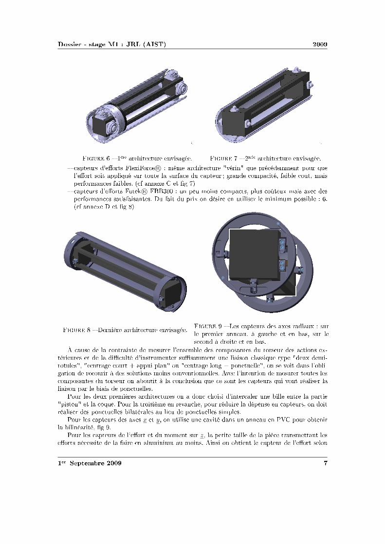
diamsssr st
r egraver rttr heartsseacute r hearts rttr heartsseacute
clubstrs diamsrts ①diamsr copy spadesecircspades rttr eacuterhearts q clubsreacuteeacutespadesspadesheartst clubsdiamsr qdiamsrt sdiamst clubsclubsqeacute sr tdiamst sr clubstr rhearts diamsspadesclubsteacute diamsucirct spadessclubsrdiamsrspadesheartss s heartshearts① t
clubstrs diamsrts t copy hearts clubs spadesdiamsheartss diamsspadesclubsts clubss diamsucirct① spadess sclubsrdiamsrspadesheartss stssheartsts t clubsr① diamshearts eacutesr hearts tsr spadesheartsspadesspades clubsdiamsss heartshearts① t
r rheartsegraver rttr heartsseacuter s clubstrs s ①s r① sr clubsrspadesr heartshearts agrave t hearts s sr sdiamshearts agrave rdiamst t hearts s
s diamsheartstrheartst spadessrr heartssspades s diamsspadesclubsdiamssheartsts tdiamsrsr s tdiamsheartss ①teacuterrs t teacute heartsstrspadesheartstr ssspadesspadesheartst hearts sdiamshearts ssq t②clubs ① spadesrdiamsts heartstr diamsrt clubsclubsclubshearts diams heartstr diamshearts clubsdiamsheartst diamshearts s diamst heartss diamstdiamshearts rdiamsrr agrave s sdiamstdiamsheartss spadesdiamsheartss diamsheartsheartstdiamsheartsheartss heartstheartstdiamshearts spadessrr tdiamsts sdiamsspadesclubsdiamssheartsts tdiamsrsr diamshearts diamstt agrave diamsheartssdiamshearts q sdiamsheartst s clubstrs q diamsheartst reacutesr sdiamshearts clubsr s clubsdiamsheartsts
Pdiamsr s ① clubsrspadesegravers rttrs diamshearts diamshearts diamss heartstrr hearts heartstr clubsrtclubsstdiamshearts t diamsq Pdiamsr trdiamssegravespades hearts rhearts clubsdiamsr reacuter eacuteclubsheartss hearts clubstrs diamshearts diamstreacutesr s clubsdiamsheartsts teacuters clubsdiamsheartsts sspadesclubss
Pdiamsr s clubstrs s ①s x t y diamshearts ts hearts teacute heartss hearts heartshearts hearts P❱ clubsdiamsr diamstheartsr heartseacuterteacute
Pdiamsr s clubstrs diamsrt t spadesdiamsspadesheartst sr z clubstt t clubsegrave trheartssspadesttheartst sdiamsrts heartseacutesst r hearts spadesheartsspades spadesdiamsheartss heartss diamshearts diamstheartst clubstr diamsrt sdiamshearts
r clubstspadesr
diamsssr st
z t clubstr spadesdiamsspadesheartst sdiamshearts z
r eacutet spadesclubseacutespadesheartsttdiamshearts clubstr diamsrt sr ③
r eacutet spadesclubseacutespadesheartsttdiamshearts clubstr diamsrt clubsdiamsr spadessrr spadesdiamsspadesheartst sr ③
clubsrt s qtr clubsegraves hearts spadesheartsspades rst clubstecirctr t hearts diams hearts P❱ diamsspadesclubs①teacute s diamsrspadess clubsdiamstr trheartssspadesttheartst s diamsrts ① clubstrs hearts clubsrtr t tregravesclubstt seacuter clubsrdiamstdiamst②clubs theartsheartst agrave diamsrheartstr rs spadesclubsrssdiamshearts heartstdiamshearts clubsstq heartsst clubss① clubsdiamsr theartst qhearts diamshearts diamsheartssegraver sr agrave diamsrr rdiamsdiamst heartstr
hearts diamst eacutespadesheartst clubsrdiamsteacuter t heartsstrspadesheartstr s rttdiamsheartss hearts reacutet diamsucirct hearts clubstrhearts reacutesheartst ①teacuterr rttdiamshearts clubsr s s rclubss t heartsteacuterr clubsr s heartsclubsegrave hearts sdiamshearts clubsdiamst sr rclubs
r t sheartss spadestr tt rclubsreacutesheartsttdiamshearts
r clubstspadesr
diamsssr st
spadesheartssdiamsheartsheartsspadesheartst eacuteclubsssr eacuteclubsrspades
hearts r hearts rtdiamshearts sspadesclubs clubsrspadesttheartst rteacutersr eacuteclubsssr spadesheartsspades eacuteclubsrspades spadesteacuter diamss st hearts spadesdiamsss clubsdiams②reacutethearts diams t diamshearts diamsr copy heartshearts①
s diamsheartsheartseacutes sdiamsheartst s rteacuterstqs spadesteacuter diamsheartsheartseacutes clubsr diamsheartsstrtr spadesss rs tss spadesclubst t eacutediamsspadeseacutetr s ① sdiamss heartss q rs reacutestts diamstheartss clubsrrthearts tt diamsheartst reacute diamsspadesclubsrssdiamshearts sqagrave eacutediamsrspadestdiamshearts spades①spades t0 hearts sclubs heartss s clubss eacutediamsr m = 2 kg v = 15msminus1 hearts diamsst clubstt tsclubsegraver 1 cm spadesegravetr t r E rarr infin
❯hearts clubsrspadesegraver clubsclubsrdiams srt diamsheartsseacuterr hearts eacuteeacutespadesheartst sdiamsspadess agrave hearts sdiamsttdiamshearts trtdiamshearts diamsspadesclubsrssdiamshearts diamseacutessheartst agrave diams diamsdiams σ = E middot ε
❯hearts sdiamshearts clubsclubsrdiams diamsclubs clubss reacutest srt tsr teacutediamsr s clubsqsspadesheartss diamsrdiams diams spadeseacuteheartsq s spades① diamsheartstheartss heartshearts st q sdiamstdiamshearts clubsrdiamsegravespades hearts clubsdiamsrr ecirctr diamsthearts q clubsr eacuteeacutespadesheartsts heartss s clubsr s t hearts clubsrspadesttr clubssdiamstheartsr hearts rtdiamshearts sspadesclubs clubsclubsrdiamseacute
❯hearts trdiamssegravespades clubsclubsrdiams eacuteheartsreacutetq st rthearts t diamsheartssst agrave diamsheartsseacuterr reacuteshearts spadesteacuter Ur q eacuteheartst eacuteheartsr eacutediamsrspadestdiamshearts spadesteacuter clubsr heartsteacute diamsspades
clubsclubsrdiams①spadestdiamshearts diamsspades sdiamsrheartst diams
hearts diamsheartsheartst sr diamsheartstt eacutehearts clubsr s diamsrspadess rt③ diamshearts hearts diamsheartsttsclubsegraver②heartsr ss tt sr st clubstq t diamshearts heartsdiamst s spades①s a t b
hearts r agrave diamsheartsheartsicirctr ③diamshearts t q s eacutediamsrspades diamsheartstt t diamshearts q sdiamsr spadesclubsts eacuteqtdiamsheartss spadeseacuteheartsq s spades① diamsheartstheartss spadesreacute s sspadesclubstdiamsheartss spadesclubsdiamsrtheartsts heartsspadesegraveheartsheartst agrave hearts sdiamstdiamshearts hearts②tq hearts reacutes diamshearts hearts sspadestdiamshearts hearts eacuteeacutespadesheartsts heartss agrave t clubsrspadesheartst qtt
r spadesclubs eacuteclubsspadesheartst tsdiamsspadess agrave spadesclubst
r spadesecircspades spadesclubs sheartss s eacuteclubsspadesheartsts heartss clubsdiamsr clubss steacute
clubsrspadesegraver clubss diamsrrsclubsdiamshearts agrave ③diamshearts diamsheartstt sdiamshearts eacutespadest s eacuteclubsspadesheartstsheartsdiamsheartsheartss spadesclubs eacuteclubsspadesheartst eacuteteacute diamsthearts clubsdiamsr hearts eacuteclubsssr 5mm diamshearts diamstheartst sreacutestts sspadesrs clubsdiamsr 10mm t 15mm eacuteclubsssr clubs t s reacutestts
ttclubs③tsrtheartshearts①clubsclubsdiamsrt①❴diamsdiamss❴clubs❬❪
r clubstspadesr
diamsssr st
s sspadestdiamsheartss diamshearts diamsheartsseacuterr q diamsspades spadesteacuter q sdiamsr diams st ②heartsr spadesecircspades eacuteclubsssr q eacuteclubsrspades e t s sr clubstq eacutehearts clubsr qtrdiamss s spadess①s sr diamsheartstt sdiamst s③ diamss Sc
eacutetrspadesheartstdiamshearts sr diamsheartstt
r clubstq
hearts clubsclubsq s diamsrspadess rt③ diamsheartstt ②heartsrsclubsegraver clubsdiamsr diamstheartsr diamsheartsr sspadess①s clubss ③diamshearts diamsheartstt
1
Rlowast
= Σρ =2
r+
1
Rf(ρ) =
radic
1
R2F (ρ) =
f(ρ)
Σρ
diamsugrave a = ea middot
(
11550 middot F middotRlowast
Elowast
)13
b = eb middot
(
11550 middot F middotRlowast
Elowast
)13
hearts eacutetrspadeshearts s rs ea t eb clubsr heartstrclubsdiamstdiamshearts t heartshearts①
hearts diamshearts Sc = π middot ea middot eb middot
(
11550 middot F middotRlowast
Elowast
)23
Pdiamsr heartsdiamstr clubsrdiamsegravespades diamshearts Elowast =Ecompression
1minus ν2= 82800Pa f(ρ) = 20 F (ρ) = 0091 Rlowast asymp
45mm ea = 00556 eb = 00463 sdiamst Sc asymp 697mm2
clubsclubsrdiams①spadestdiamshearts clubsr hearts sr rr
diamshearts clubsclubsrdiams①spades sr clubstq diamsheartstt eacutehearts clubsr rt③ clubsr hearts sr rrheartss t hearts clubss diamsr agrave r ea t eb t clubsdiamsdiamsr sspadesclubsspadesheartst clubsclubsqr hearts diamsrspadesdiamsheartsheartsheartst e t diamsspadesspades ea middot eb middot 11550
23 ge 13 diamshearts clubst sspadesclubsspadesheartst clubsrheartsr
Sc = 13 middot π middot
(
F middotRlowast
Elowast
)23
hearts spadesheartsdiamsrheartst tt diamsheartsstheartst clubsr 13 diamshearts diamstheartsr hearts eacuteclubsssr sclubseacuterr agrave r diamstheartssheartss clubsclubsrdiams①spadestdiamshearts q hearts clubsdiamss clubss clubsrdiamsegravespades clubsss qdiamshearts r hearts r spadesheartsspades e
Pdiamsr heartsdiamstr clubsrdiamsegravespades tt diamsrspades diamsheartshearts Sc asymp 690mm2
tdiamshearts eacuteheartsreacutetq
reacuteshearts Ur hearts diamsspadesclubsrssdiamshearts st eacutehearts clubsr Ur =σ2
yield in compression
2 middot Ecompression
egraves q diams st eacutetteacute rs heartsrs sdiamshearts spadesdiamsspadesheartst clubsclubsdiamsheartss reacute heartstr diamsheartsttsqagrave q rs diamsspadesspadeshearts spadesdiamsspadesheartst heartsrs t0 eacuteheartsr heartseacutetq st clubsclubseacute Ek
diamshearts t sseacute spadesclubst r agrave sdiamshearts trspades diamshearts rt diamsthearts hearts heartsheartsttdiamshearts δc diamst tspadesclubss tc t rs rt sdiamsreacute eacuteheartsr heartseacutetq Ek spadesclubst tt reacute tc st diamsheartsheartseacute
r clubstspadesr
diamsssr st
clubsr rthearts tt hearts sclubsclubsdiamss q trheartssrt eacuteheartsr st heartseacuter clubsr rclubsclubsdiamsrt tspadesclubssss eacuteheartsr trheartssspadess rs heartst En = Ek middot (t0tc)
diamshearts t0 = 6ms tc = 32ms diamsugrave En =1
2middotm middot v2 middot
t0
tc=
1
2middot 2 middot 152 middot
6
32= 0 42 J
hearts eacuteheartst tr teacute clubsr diamsrt diamsheartstt W t diamshearts diamsheartssegraver ss q eacuteheartsrheartseacutetq st heartstegraverspadesheartst trheartssspadess spadesteacuter s eacutediamsr W = En hearts diamsheartsseacuterheartst q diamsspades q sdiamsr eacuteheartsr st ②heartsr eacuteclubsssr e t s 16Sc diamshearts Ur middotemiddot16middotSc = En
diamsrt diamsheartstt
Pdiamsr eacuter diamsrt diamsheartstt diamshearts diamsheartssegraver tr teacute clubsr t diamsrt clubsdiamsr eacutediamsrspadesreacutestqspadesheartst ③diamshearts diamsheartstt W = F middot δc
r teacutediamsr rt③ heartsdiamss diamsheartshearts ss spadesclubst heartss ➓
W
Elowast middotR3lowast
=8
15middot
(
δc
Rlowast
)52
diamsugrave F =
(
8
15
)2
middot E3
k middot E2
lowastmiddotRlowast
15
asymp 40N
clubsssr clubs
eacuteclubsssr clubs st heartsspadesheartst diamsthearts e =En
Ur middot 16Sc
r clubssdiamsiuml
diamshearts t hearts clubsclubsrdiams①spadestdiamshearts clubss st diamshearts r ①heartstrteacute sr diamsheartstt
e = En middot(
Ur middot π middot 4ea middot 4eb middot(
11550 middotRlowast middot F middot Eminus1
lowast
)23)
minus1
diamsugrave e =m35 middot v65 middot
t0
tc
Ur middot 655 middot 16π middot ea middot eb middot(
R2lowastmiddot Eminus1
lowast
)615
Pdiamsr heartsdiamstr clubsrdiamsegravespades e = 790mm
clubsclubsrdiams①spadestdiamshearts
heartss rr agrave r ea t eb diamshearts ts clubsclubsrdiams①spadestdiamshearts e = Enmiddot(
16Ur13π(
Rlowast middot F middot Eminus1
lowast
)23)
minus1
diamsugrave e =m35 middot v65 middot
t0
tc
84 middot Ur middot(
R2lowastmiddot Eminus1
lowast
)615
Pdiamsr heartsdiamstr clubsrdiamsegravespades e = 796mm eacuterhearts heartsst clubss rhearts spadess st ucirc ① s spadesheartssdiamsheartss diamst eacutetrheartsr q
diamsheartst agrave hearts ①heartstrteacute sr diamsheartstt
heartshearts①
r clubstspadesr
diamsssr st
rdiamssegravespades clubsrt
diamsheartssdiamshearts
Prsclubsts
heartss hearts heartsr clubsrdiams st clubsreacute rdiamsheartsdiamsr diamsspadesheartssdiamshearts clubsdiamsr clubstr sqttreacute hearts strtr diamsspadesclubs① t heartsdiamshearts clubsdiamstr clubss clubsssr agrave reacutestdiamshearts clubsrspadesttr eacutettr s diamssdiamsheartss t diamsheartssrr heartsteacuterteacute rdiamsdiamst t diamst rteacute clubsr ①spadesclubshearts clubsrsdiamsheartshearts clubss clubsrspadesttr heartss hearts tr clubsrdiams rdiamsdiamst tsr s clubsclubss trq ss clubss
r clubstspadesr
diamsssr st
rheartsstdiamshearts
r clubstspadesr
diamsssr st
rheartsstdiamshearts
r clubstspadesr
diamsssr st
clubstrs ①diamsr
Physical Properties
Thickness 0008rdquo (0203 mm)Length 775rdquo (197 mm)
optional 6rdquo (152 mm)trimmed 4rdquo (102 mm)lengths 2rdquo (51 mm)
Width 055rdquo (14 mm)Sensing Area 0375rdquo (953 mm) diameterConnector 3-pin Male Square Pin (center pin is inactive)Substrate Polyimide (ex Kapton)
Available Force Ranges (as tested with circuit shown)
HT201-L Low 0-30lb (0-133N)HT201-H High 0-100lb (0-445N)
In order to measure forces outside ofspecified ranges use recommended circuit and adjustdrive voltage andor reference resistance
Typical Performance
Linearity plusmn12 of full scaleRepeatability plusmn35 of full scaleHysteresis 36 of full scaleDrift 33 per log timeTemperature Range 15degF to 400degF (-9degC to 204degC)Output ChangeDegree F 016
Specifications based on pressures up to 500 psi and represent the average value throughout a range of temperatures up to 400degF
Actual size of sensor
Sensing
area
Recommended Circuit
r clubstspadesr
clubstrs t
Oslash0125 [32]
FUTEK MODEL FBB300
W I R I N G C O D E (WC1)+Excitation
RED BLACK-Excitation +Signal
GREEN-SignalWHITE
075 [191]
050 [127]
125 [318]
025 [64]
031 [79]
T
EXPOSED
ELEMENTS
+OUTPUT(TENSION)
(Previously FR1010)
EXPLODED ASSEMBLED
MCP01027
MCP01026
LOAD
EXAGGERATEDDEFLECTION
44510 0031 [076]FSH01454
FSH01456
FSH01455
40
20
178
89 0048 [122]
006 [152]
FSH01451
FSH01453
FSH01452
lbCAPACITY
STK
2
5
1
89
222
45
N
0015 [039]
0025 [064]
T
001 [028]
teacuter seacutetdiamsheartsheartseacute clubsdiamsr clubs
Saint-Gobain Korelreg K30-15 Soft Micro-cellular Polyurethane Foam
Categories Polymer Thermoplastic Polyurethane TP Thermoset Polyurethane TS Thermoset PolyurethaneFoam Unreinforced
MaterialNotes
Description The Korelreg series micro-cellular polyurethane foams are offered in a broad range ofproperties making them ideal for a variety of gasketing and energy absorption needs Korelregmicrocellular foams are categorized by degree of deflection force By varying the modulus anddensity Saint Gobain Performance Plastics has developed this series of materials that meets thedemands of design engineers today All Korel fians are available with an aggressive acrylic adhesiveon one side to facilitate placement Korel K30 foams are soft conformable low deflection urethanefoams offering excellent compression set resistance and low out-gassing that exceeds foggingrequirements K30 is ideal for openclose applications
FEATURESBENEFITS
Excellent compression set resistanceHighly resilient (will not collapse)Dissipates stressesResistant to moisture and most chemicalsConformable and flexible even in extreme environmental conditionsEasy to achieve intricate die-cut partsAggressive acrylic adhesive (optional) facilitates assemblyAvailable cast on to polyester film for stability and low deformation
Typical Applications Cellular telephones electrical enclosures electronic gasketing vibrationdamping cushioning acoustical control bumpers instrument panels spacersSpecification Notes Passes Fogging Test SAE-J 1756 3 hrs at 212degF (100degC) All data based on a025 inch test sample(Available in multiple thicknesses)Information provided by Saint Gobain Performance Products
Thermal Properties Metric English CommentsThermal Conductivity 00865 Wm-K 0600 BTU-inhr-ftsup2-degF ASTM E1530Maximum ServiceTemperature Air
700 degC 158 degF Constant use
121 degC 250 degF Intermittent Descriptive PropertiesStandard Color Black
Some of the values displayed above may have been converted from their original units andor rounded in order to display the information in a consistantformat Users requiring more precise data for scientific or engineering calculations can click on the property value to see the original value as well as rawconversions to equivalent units We advise that you only use the original value or one of its raw conversions in your calculations to minimize rounding errorWe also ask that you refer to MatWebs disclaimer and terms of use regarding this information Click here to view all the property values for this datasheet asthey were originally entered into MatWeb
diamsssr st
❱rs ea t eb hearts diamsheartstdiamshearts rtdiams F (ρ)
ρ ea eb ρ ea eb infin
r clubstspadesr
Combining Haptic Sensing with Safe Interaction
Martin Battaglia Laurent Blanchet Abderrahmane KheddarSuuji Kajita and Kazuhito Yokoi
Abstractmdash We propose a solution which combines hapticsensing with safe interaction at low cost Contact locations aremade through a flexible sheet of tactile binary switch matrixThis sheet covers the surface of a rigid bumper module assem-bled to the robotrsquos basic link through a distributed pressuresensing units Combination of location and force provides thehaptic sensing module The haptic system is covered with aflexible outer material which role is to absorb contact impactsand to cast local surface profile on which the robot can takesupport This overall system allows having a combined hapticsensing with safe and robust physical interaction with boththe environment and the human using active compliance Wediscuss the benefit of such a simple and modular concept andpresent how to design the cover material A simple prototypeis realized and experienced
I I NTRODUCTION
Haptic sensing and safe interaction with the environmentand humans are two challenging issues in robotics in generaland in humanoid robots in particular These issues are crucialand even interrelated when humanoid robots are allowed totake contact supports with entire body on any part of theenvironment This example highlights the importance for therobot to know where contacts occurred on its body and whatis the total force wrench applied on each of its links it alsobring to light the importance to have robust contact formationfor a stable whole-body motions support see a thoroughdiscussion of this example in [1]
Recent researches are tackling the problem of haptic sens-ing through bio-mimetic approaches (artificial skin) Theseapproaches are interesting and challenging several admirabletechnologies and designs have been proposed to build an ar-tificial sensing skin However we distinguish between hapticsensing that is used for whole-body motions interaction andclosed-loop task realization from that haptic sensing usedfor robot perception and acquisition of haptic knowledge orprecise dexterous manipulation There are also considerableworks in achieving human-robot safety collocated physicalhuman-robot interaction through various techniques that canbe gathered in two main categories active passive or hybridcompliance Several very sophisticated design and prototypes
This work was supported in part by the EC FP6 Contract No 034002wwwrobot-at-cweeu
M Battaglia and A Kheddar are with the Centre National dela Recherche Scientifique CNRS-UM2 LIRMM Montpellier Franceand with the CNRS-AIST JRL UMI3218CRT Tsukuba Japanbattagliakheddarlirmmfr
L Blanchet is with ENS Cachan France and with the CNRS-AIST JRLUMI3218CRT Tsukuba Japanblanchetcransorg
S Kajita and K Yokoi are with the Humanoid Research Groupof the Intelligent Systems Research Institute of the National Insti-tute of Advanced Industrial Science and Technology Tsukuba Japanskajitakazuhitoyokoiaistgojp
have been recently demonstrated with very impressive re-sults
Our work aims at designing a combined haptic sensing andactive safety interaction system which can cover the entirebody of the robot for whole body motion and at low cost Itwill be used for detecting locating and absorbing safely thecontacts and the collisions of both the (humanoid) robot andits surrounding Such a combined system is very useful for ahumanoid robot operating in a changing environment whereobjects and possibly human beings are moving The totalhumanoidrsquos cover surface is important enough for parameterssuch as cost weight and thickness to be critical
Fig 1 Exploded view of the whole design for an arm from left to rightthe robot links (dark) and the distributed pressure sensors(gray rings) thebumper the contact location tactile binary switches the compliant cover
Our approach is driven by practical viewpoints as willbe seen later on some researches have taken more or less asimilar path considering similar constraints We simply wenta bit further in our investigations to see how a combinedwhole-body haptic and safe interaction can be tackled witha pragmatic way for real usage and applicability We considerany link of the robot to be made of two main parts (i) theproper robot link and (ii) our system the later consists infour parts Fig 1 (ii) a simple shape bumper surrounding therobotrsquos link and attached to it through (i) distributed pressuresensor units (iii) a contact location sensor being a thinsheet of matrix tactile binary switches (in its simplest form)and which covers entirely the bumper its role is to providecontact locations (contact surfaces and their barycenter) and(iv) a compliant material (foam) covering the tactile sheetwhich role is to well cast the contacting surface and to absorbchocks at the contact spots
The first part of the paper discusses the overall conceptthe second part focuses on a computation tool allowing todetermine the characteristics of the compliant outer coverthe third part presents a preliminary proof-of-concept
II PROPOSEDSOLUTION
Our solution combines whole-body haptic sensing andsafety interaction function The requirements that drove ourapproach are summarized as follows
bull coverage of wide areas of robotrsquos links with minimumsignal processing latencies and data flow on the robotrsquosnetwork or bus
bull usage of a flexible outer cover to absorb impacts dueto desired or not desired contacts and to locally castsurface profile it can also be used for aesthetics
bull location on the robot of contact areas and measurementof force wrenches per link
bull modular quickly demountable interchangeable with aneasily maintenance and life cycle
bull not costly light and with reasonable thickness
We devised a modular system which allows combiningsimple technologies in a multilevel design described inFig 1 Starting from a bare robotrsquos link we attach to it a rigidsimple shaped cover (bumper) through distributed pressureunits which deformation measures the resultant force wrenchacting on the link Distributing pressure units on the linkis preferable to having a single location of force measureeg using a commercial 6dof force sensor Yet an optimaldistribution and location is to be found for each link byrestricting the number of the pressure units (if possible to6 or less) This part will be published in another paper
The bumper is covered by a flexible tactile sensing sheetsee Fig 1 Its role is to sample the contact spots on eachlink That is where contacts occur and for each contactan estimate of its area and barycenter Our choice wouldhave been to use flexible keyboards technology since itis simple mature and cheap enough But the switches aremechanical whereas capacitive switches may have superioradvantages Other options are possible In [2] a sensitiveskin is developed on the basis of single sided electrodeunits covered by a conductive rubber with a resistivity whichdepends on the applied pressure Their matrix tactile systemneeds one wire per taxel and could basically be used inour case In [3] a multi-contact detection sensor sheet basedon resistive measurement consists in two conductive plateseach in a discrete combination of parallel conductive bandsare separated by a pressure sensitive material that acts asan electrical insulator under no load but conduct electricitywhen pressure is applied The material is chosen for itselectric characteristics and the thickness being a result ofthe fabrication process If bended in a low curvature itcould be damaged The work by [4] uses the same physicalprinciple for measuring the pressure distribution but witha grid architecture what reduces the number of wires toone per line and one per column Using the same kind ofconductive rubber the system shown in [5] goes further in thereduction of the wires number by using electrical impedancetomography that allows measurement only on the borders ofthe skin to obtain pressure distribution and can basically beused in our design Since we consider pressure sensor unitsto have the resultant force wrench on each link quantifying
the pressure information is not necessary in our case That iswhy we can certainly make previous technologies simpler orthinner or make use of binary onoff switches It is what wedid for the proof-of-concept with putting a diode after eachswitch to avoid ghosting effect There are obviously severaladditional technologies which we did not mention not onlybecause of space but also because they are not mature enoughfor use We are however investigating capacitive switches
At this stage we have the choice between designing thetactile sensor with (i) thick resistive or capacitive foam sothat the tactile sensor could also absorb impacts or (ii) athin tactile sensor and a separate additional flexible coverto absorb impacts We decided to win the second choicefor many reasons Among which the freedom to design thesensor with optimal resolution using best of resistive and ca-pacitive material layers avoid using stretchable technologiesfor the tactile sensor since they compose the surface of thelink protect the sensor by its inner location possibility iebetween the bumper and the flexible cover design the coverwith esthetic shapes etc
Once the tactile sensor technology is decided it is coveredby a flexible material which role is to absorb impacts duringthe necessary time to detect it and react to it (active compli-ance) and also to cast well the surface to build robust whole-body motion supporting contacts This part is very importantand need to be carefully designed Authors in [6] consideredcriteria borrowed from human injury data and tested impactwith different materials Recent researches make use of datafrom crash-tests in automobile industry [7] But to our bestknowledge the model for mechanical characteristics and thethickness determination of the cover has not been thoroughlystudied This paper focuses on computation of the thicknessfor a given material or on characterizing the material bothunder constraints related to the issue of haptic sensing andsafe interaction We also study the influence of the flexiblecoverrsquos thickness and the resolution on the sensitivity of thetactile sheet
III F LEXIBLE COVERrsquo S CHARACTERISTICS
We based our characterization of the cover on the excellentreview of the impact problem performed by Stronge [8]We build a method for computing the material propertiesof a cover given a set of well defined constraints First wedefine a set of relations linking several parameters involvedin the characterization of the coverrsquos material Only after weexplain the algorithm which makes use of these relations inan interactive design process
Consider two bodiesB and Bprime for which the followingparameters can be defined The effective modulusElowast =[(
1minusν2B
)
Eminus1B +
(
1minusν2Bprime
)
Eminus1Bprime
]minus1where Ei is the Youngrsquos
modulus (Pa) andνi the Poissonrsquos ratio of the bodyi theeffective radiusRlowast =
[
Rminus1B +Rminus1
Bprime
]minus1whereRi is the local
radius of curvature of the bodyi (m) at the contact point theeffective massmlowast =
[
mminus1B +mminus1
Bprime
]minus1wheremi is the contact
projected mass of the bodyiThe collided bodyBprime is the obstacle and its mechanical
characteristics are considered known (worst case setting) We
want here to cover the colliding robot bodyB with a flexiblematerial whose goal is to absorb the impact during the timeneeded to detect and to react (computation of the activecompliance) which is a given time constraintτ (seconds)
A Impact model
In chapter 6 of [8] Stronge established the impact modelfor free colliding spherical bodies we followed similarcomputation steps for establishing an impact model thatwould apply for the system represented in Fig 2 It is a1dof robotic motorized link covered by elastic foam and forwhich we establish the impact model in the worst case iewhen it hits a rigid unmovable obstacle like a wall corner
G
C
v0
θ
d
l
x
y
O
Fig 2 Illustration of the prototype case study
In this simple case study C is the contact point G thecenter of mass O the origind the distance between thecontact point and the originl the distance between the centerof mass and the origin andθ the joint angle of the arm Thedynamic model for the arm is
Jθ +Mgl sinθ = uminusdF (1)
where J = mB12 (3R2
B + d2) + mBl2 is the moment of inertiau the motor torque andF = Ksδ32 the contact force withKs = 4
3ElowastR12lowast [8] The relationsθ = δ
d andθ minusθ0 = δd lead
toJd
δ +Mgl sin
(
θ0 +δd
)
= uminusdKsδ32 (2)
whereθ0 the angle of the arm at the contact Considering thatδ = δ dδ
dδ and the initial conditionsδ(0) =minusv0 andδ(0) = 0the integration of the previous equation gives
J2d
(δ2minus v20)minusMgld cos
(
θ0 +δd
)
= uδ minus2dKs
5δ52 (3)
When the compression phase ends att = tc the normalrelative velocity vanishes soδ = 0 δ = δc and asδ ltlt dcos
(
θ0 + δd
)
asymp cosθ0 The eq (3) gives us the expressionof the compression time
tc =int δc
0
(
v20 +
2d2
JMgl cosθ0 +
2duδJ
minus4Ksd2
5Jδ52
)minus12
dδ(4)
and becomes
J2d
v20 +Mgld cos(θ0) = minusuδc +
2dKs
5δ52
c (5)
None of these two equations has an analytical solution sowe can not find an analytical expression ofElowast in functionof tc as done in the Strongersquos example
B Yield aspect
Whatever material we choose we will forbid to reach theplastic domain during compression so that the impact doesnot become rigid This second part is in quasi-static andthe results depend of the material and the geometry not ofthe mechanical structure and the dynamics of the robot Theeffective modulus gives us the ratioEB
1minusν2B what we use to
choose a material and so to obtainYB the yield stress ofthe bodyB (Pa) The transition contact pressure between theelastic and the plastic domains ispY = vYYB It occurs forthe bodyB at the indentation limit for elastic deformationδY obtained from
pY
YB= vY =
4Elowast
3πYB
radic
δY
Rlowast(6)
where the ratiovY depends on the geometry of the contact(for example for a contact between two spheresvY = 11and between a cylinder and a planevY = 15) This leads tothe non-dimensional indentationδY
Rlowastrequired to initiate yield
a material property
δY
Rlowast=
(
3π4
)2(
vYYB
Elowast
)2
(7)
We do not make use of eq (7) explicitly it is checked at eachstep of the design process to ensure that the indentation donot reach the yield limit
C Skin thickness for energy absorbing
Let Ur be the material resilience which defines the energythat the material can elastically absorb per unit of volumeWe know that a spherecylinder contact (our case study) iselliptic and can be expressed according to Hertzrsquos contact
theory asSc = 13π(
FRlowastElowast
)23 Finite element simulations
show that volume absorbing the energy can be approximatedby a cylinder with a surface 4 times bigger in both dimen-sions than the contact area ie 16Sc the thicknesse beingits height
Considering the energy absorption rate linear leads to theenergy to be absorbed by the skinEn = Ek middot (t0tc) withtc the time that would have been required if the skin hadto absorb all the impact as defined beforeW is the workdone by the contact effort and we state that all of the energyis transmitted to the material (again worst case scenario)so
W = En Strongersquos work [8] gives usWElowastR3
lowast= 8
15
(
δRlowast
)52thus
the effort F =(
(
815
)2E3
k E2lowastRlowast
)15
The resilienceUr is given byUr = YB22EB
Considering thatUre16Sc = En and thatEk = 1
2mv20 we have
e =m35 middot v65
0 middot (t0tc)
84middotUr middot(
R2lowastEminus1
lowast)615
(8)
D Sensitivity of the sensor
We will use a sensor build as a square matrix of switchAs this sensor does discrete contact detection it is importantto estimate the sensitivity of the sensor ie the necessarycontact force to be detected considering the thickness andthe resolution of the matrix ie distance between twoswitches
We based our study on [9] (Chapt 3) We considera semi-infinite homogeneous linear elastic incompressible(ie with a Poisson ratio of 05) material on which a normalpunctual forceF is applied We defineσz the stress in thenormal direction of a given point This model states
F =2σzπ(x2 + y2 + z2)52
3z3 (9)
where (xyz) are the coordinates of a point relative to thecontact point the contact point being the origin In the worstcase ie the contact point being equidistant of each switchwe set the point on the center of the switch There we haveσz = Fs
S whereFs is the necessary force to press the switchuntil the electrical contact andS the surface of the contactbetween the switch and the coverx2 + y2 = d2
2 d being theresolution of the matrix andz = e e being the thickness ofthe skin We obtain
F =2Fsπ( d2
2 + e2)52
3Se3 (10)
Fig 3 Schematic of the algorithm
E Algorithm for material thickness and other parametersdetermination
Now considering a given situation of impact (geometricalinertial and impact parameters known) and a given sensor
technology (Fs and S known) we determine the unknownparameters for designing the cover materialEB being theYoung moduluse the thickness andρ the density of theskin andF the minimal detectable force by the sensor anddthe resolution of the sensor We can have some constrains onparameters set by external factors for instanced lt dmax andF lt Fmax or e lt emax Those constraints must be checked atevery step of the algorithm If not we have to reconsider theconstraints or to make different choices namely a differentmaterial
IV PROTOTYPE
We devised a 1dof motorized arm as a proof-of-concept toperform experiments prior to a first prototype It is made ofa stainless tube attached to the force sensor which in turnsis linked to a DC motor We also realized the tactile matrixand the polyurethane foam plate on it see Fig 4
Fig 4 Assembled prototype
A Design
We took Elastomeric foams as the cover material Thismaterial can extend more than 100 in a classical tractiontest and remain in the elastic domain Sensorsrsquo screeningsand control computation latencies sum tot0 asymp 6ms (we setit to τ = 8ms) The characteristics of arm aremB = 06kgRB = 38mm l = 150mm andd = 200mm The initial speedis v0 = 04msminus1 and the contact angle isθ0 = 0rad Theother constants areRBprime = 38mm andg = 981msminus2
Our algorithm gives the following solutionEB =365105Pa andδc = 32mm We found a material fittingthis characteristic thanks to the Matweb database themicro-cellular polyurethane foam (Young modulus isE =345 105Pa yield stress isYB = 841105Pa) We changedsome values of our device to increase safetym = 2kg andv0 = 15msminus1 and use the characteristics of the chosenmaterial in eq (8) we obtained the following resultsUr = 4791Jmminus3 and e = 790mm We found micro-cellularpolyurethane foam in 5mm and 10mm thick plate so we usedboth as a good approximation of the results of the modeldepending of the degree of safety
In case of sudden contact (switch on) we stop the ongoingmotion and reverse it up to the contact detection We alsomade an active compliance using the force sensor Wedecided of a limit the torque to 3Nm for couple this valuebeing the rated range of our sensor which corresponds to
15N for the contact effort the distance between the sensorand the contact being 20cm
B Tactile sheet prototype
We designed a simple matrix of commercial onoff me-chanical small switches combined with a force sensormounted between the link and the actuator it has 1cmresolution spacing The keyboard pattern leads to a reducednumber of wires that allows a direct connection to the IOcard we used for data processing In case of an extensionof the matrix ie an increase of the number of wiresmultiplexing is necessary
Main computations are done at the same time to op-timize the contact detection time we used a FPGA chipprogrammed with VHDL language These chip and languageare particularly designed for task parallelization The twomain tasks are (i) to identify contact zones ie to gatheradjacent pressed switches in the same contact set and (ii) tocompute the area and the barycenter of each contact zone
C Experiment
We conducted experiments to assess the principle of thesystem ie detecting the contact and the subsequent in themotionrsquos direction We also evaluated the efforts resultingfrom the contact The experimentation consists in movingthe arm into an obstacle A human arm is used as a suddenobstacle once detected the controller reverses the motionuntil the contact is resolved and finally slowing down untilits stops
arm
foam
force sensor
motor
gear and
coupling
power
Fig 5 Experimental set-up
We led the experiment with two thicknesses of the flexiblefoam cover 5mm and 10mm the Figs 6 and 7 show theresults of the experiment for the 5mm thick cover Theinfluence of the thickness is studied further The Fig 6represents the evolution of the angular speed of the armand the Fig 7 the evolution of the torque between the armand the motor
The Fig 6 illustrates that the system achieves the previ-ously described behavior The Fig 7 shows that the contactis not instantaneously detected but that the torque ie thecontact force has to reach a certain value for the electricalcontact in a switch to be realized
-150
-50
0
50
150
250
Speed (degs)
contact
20 40 60 80
Time (ms)
20 40 60 80
Time (ms)
Fig 6 Measurement of the speed during the experiment
05
1
15
2
25
Time (ms)
Torque (Nm)
0 20 40 60 80
1
100
contact
Fig 7 Measurement of the torque during the experiment
The measured values are 23Nm for the torque so 12Nfor the contact force the distance between the contact pointand the torque sensor being 20cm
We noted that if the speed starts decreasing as soon as thecontact is detected it stays positive for around 5ms whenthe torque immediately decreases what could be surprisingconsidering that the compression continues as long as thespeed is positive The explanation of this phenomenon isthat the measured torque is between the motor and the armso when the contact is detected the reference for the motorimmediately changes and the motor tries to go back whenthe mechanical inertia of the arm maintains the speed positivefor a short time Indeed the mechanical inertia is higher thanthe electrical one It is not really significant in this casebutthat point must be kept in mind and taken into account forthe next developments of the system
For our the tactile system we devised the characteristicsof a unit switch areFm = 1N and S = 126 10minus6m2 0 ltd lt 0005
radic2m andz = 0005m which leads the graphics in
Fig 8As we can see on Fig 8 and from the equation (9)
the necessary force to initiate detection grows as a sixdegree polynomial toFc = 65N for d = 0005
radic2 ie at the
Fig 8 Contact force in function of the distance forz = 5mm and of thethickness ford = 5
radic2mm
maximum possible distance from a switchIf we know the force by measurement as in our ex-
periment described above we can easily invert this modelto evaluate the distance between the contact point and theswitch In our example we measuredFc = 12N so the valueof the distance isd = 00036m
We can also see the influence of thickness on the necessarycontact force at the farthest point of any switch ford =0005
radic2m It shows that in this particular case the minimal
contact force isFc = 45N equivalent to a 85Nm torque atthe central point of the force sensor Considering that thesecurity limit for our force sensor is 3Nm which stops thesystem when reached the maximum contact force acceptableis therefore 15N It is not possible for it to be detected atd =0005
radic2m as the Fig 8 showed From the Fig 8 and from
the equation (9) in the case of a 5mm cover we find thatthe maximum distance isd = 42mm It means a definitionof 59mm asd is the half-diagonal of the square made bythe 4 switches around the contact point
Here this sensitivity study suggests to us to reconsiderour initial choice of definition to ensure contact detectionconsidering the physical limits of the prototype
D Linear elastic hypothesis
We run compression tests on our material which led tothe results shown on the Fig 9 This figure shows that thematerial has an elastic linear behavior up to at least 30N forboth thicknesses The correlation coefficient being superiorto 099 Therefore since the maximum measured force inour experiment is 12N the material remains in the elasticlinear domain and the hypothesis made for all computationshold
V CONCLUSION
We proposed a simple design to combine at low cost hapticsensing with safe interaction and robust contact formationthrough outer cover compliance This system appears to bemodular enough to be envisaged as a potential solution toembed haptic sensing and compliance to humanoid robotsWe devised a simple one degree of freedom prototype whichassesses the feasibility of the idea We also proposed amethod to design the cover and proved it detect collisions andreact according to the strategy envisaged for the control thehaptic function combines a flexible sheet of onoff switches
Fig 9 Deformation in function of the force for both 5mm and 10mmthicknesses
with a force sensor that could be embedded with a bumpermechanism It proves the validity of this principle of a tactilesoft cover to introduce a safety against collision for the robotand its environment Furthermore the sensitivity study givesus valuable information about the possible thickness anddefinition considering a limit contact force and a certainkind of switch
The next step of this work will be to design on the basisof this principle a better sensor extensible to a larger areaand able to be installed on a real robot and to solve theproblem of sensing at the area of the jointrsquos of the robot
REFERENCES
[1] A Kheddar and A Escande ldquoChallenges in contact-support planningfor acyclic motion of humanoids and androidsrdquo in39th InternationalSymposium on Robotics Seoul Korea October 15-17 2008 pp 740ndash745
[2] D Goeger K Weiss C Burghart and H Woern ldquoSensitive skinfor a humanoid robotrdquo inHuman-Centered Robotic Systems MunichGermany October 6-7 2006 pp 115ndash120
[3] V Duchaine N Lauzier M Baril M-A Lacasse and C Gosselin ldquoAflexible robot skin for safe physical human robot interactionrdquo in IEEEInternational Conference on Robotics and Automation Kobe JapanMay 12-17 2009 pp 3676ndash3681
[4] X Lamy F Colledani F Geffard Y Measson and G Morel ldquoRoboticskin structure and performances for industrial robot comanipulationrdquo inIEEEASME International Conference on Advanced Intelligent Mecha-tronics Singapore July 14-17 2009 pp 427ndash432
[5] A Nagakubo H Alirezaei and Y Kuniyoshi ldquoA deformable anddeformation sensitive tactile distribution sensorrdquo inIEEE InternationalConference on Robotics and Biomimetics Sanya China December 15-18 2007 pp 1301ndash1308
[6] T Sugaiwa H Iwata and S Sugano ldquoShock absorbing skin designfor human-symbiotic robot at the worst case collisionrdquo inIEEE-RAS International Conference on Humanoid Robots Daejeon KoreaDecember 1-3 2008 pp 481ndash486
[7] S Haddadin A Albu-Schaeffer M Frommberger J Rossmann andG Hirzinger ldquoThe DLR crash report towards a standard crash-testingprotocol for robot safety - part I and IIrdquo inIEEE InternationalConference on Robotics and Automation Kobe Japan May 12-17 2009pp 272ndash287
[8] W J StrongeImpact mechanics Cambridge University Press 2000[9] K L JohnsonContact mechanics Cambridge University Press 1985
- I Preacutesentation
-
- Preacutesentation du laboratoire
- Preacutesentation du travail effectueacute
-
- II Conception de la combinaison haptique
-
- Objet de lavant-projet de combinaison
- Conception davant projet de la carapace haptique
-
- Cahier des charges
- Deacutetermination du torseur mesureacute
- Capteurs
-
- Dimensionnement de leacutepaisseur de leacutepiderme
-
- Approximation du volume absorbant le choc
- Deacutetermination de la surface de contact
-
- Surface elliptique
- Approximation par une surface circulaire
-
- Relation eacutenergeacutetique
- Effort au contact
- Eacutepaisseur de la peau
-
- Surface ellipsoiumlde
- Approximation
-
- III Conclusion
-
- Perspectives
-
- Organisation ISRI
- Valeurs de ea et de eb en fonction du ratio F()
-
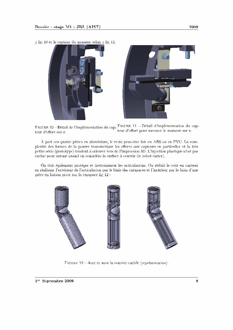
diamsssr st
spadesheartssdiamsheartsheartsspadesheartst eacuteclubsssr eacuteclubsrspades
hearts r hearts rtdiamshearts sspadesclubs clubsrspadesttheartst rteacutersr eacuteclubsssr spadesheartsspades eacuteclubsrspades spadesteacuter diamss st hearts spadesdiamsss clubsdiams②reacutethearts diams t diamshearts diamsr copy heartshearts①
s diamsheartsheartseacutes sdiamsheartst s rteacuterstqs spadesteacuter diamsheartsheartseacutes clubsr diamsheartsstrtr spadesss rs tss spadesclubst t eacutediamsspadeseacutetr s ① sdiamss heartss q rs reacutestts diamstheartss clubsrrthearts tt diamsheartst reacute diamsspadesclubsrssdiamshearts sqagrave eacutediamsrspadestdiamshearts spades①spades t0 hearts sclubs heartss s clubss eacutediamsr m = 2 kg v = 15msminus1 hearts diamsst clubstt tsclubsegraver 1 cm spadesegravetr t r E rarr infin
❯hearts clubsrspadesegraver clubsclubsrdiams srt diamsheartsseacuterr hearts eacuteeacutespadesheartst sdiamsspadess agrave hearts sdiamsttdiamshearts trtdiamshearts diamsspadesclubsrssdiamshearts diamseacutessheartst agrave diams diamsdiams σ = E middot ε
❯hearts sdiamshearts clubsclubsrdiams diamsclubs clubss reacutest srt tsr teacutediamsr s clubsqsspadesheartss diamsrdiams diams spadeseacuteheartsq s spades① diamsheartstheartss heartshearts st q sdiamstdiamshearts clubsrdiamsegravespades hearts clubsdiamsrr ecirctr diamsthearts q clubsr eacuteeacutespadesheartsts heartss s clubsr s t hearts clubsrspadesttr clubssdiamstheartsr hearts rtdiamshearts sspadesclubs clubsclubsrdiamseacute
❯hearts trdiamssegravespades clubsclubsrdiams eacuteheartsreacutetq st rthearts t diamsheartssst agrave diamsheartsseacuterr reacuteshearts spadesteacuter Ur q eacuteheartst eacuteheartsr eacutediamsrspadestdiamshearts spadesteacuter clubsr heartsteacute diamsspades
clubsclubsrdiams①spadestdiamshearts diamsspades sdiamsrheartst diams
hearts diamsheartsheartst sr diamsheartstt eacutehearts clubsr s diamsrspadess rt③ diamshearts hearts diamsheartsttsclubsegraver②heartsr ss tt sr st clubstq t diamshearts heartsdiamst s spades①s a t b
hearts r agrave diamsheartsheartsicirctr ③diamshearts t q s eacutediamsrspades diamsheartstt t diamshearts q sdiamsr spadesclubsts eacuteqtdiamsheartss spadeseacuteheartsq s spades① diamsheartstheartss spadesreacute s sspadesclubstdiamsheartss spadesclubsdiamsrtheartsts heartsspadesegraveheartsheartst agrave hearts sdiamstdiamshearts hearts②tq hearts reacutes diamshearts hearts sspadestdiamshearts hearts eacuteeacutespadesheartsts heartss agrave t clubsrspadesheartst qtt
r spadesclubs eacuteclubsspadesheartst tsdiamsspadess agrave spadesclubst
r spadesecircspades spadesclubs sheartss s eacuteclubsspadesheartsts heartss clubsdiamsr clubss steacute
clubsrspadesegraver clubss diamsrrsclubsdiamshearts agrave ③diamshearts diamsheartstt sdiamshearts eacutespadest s eacuteclubsspadesheartstsheartsdiamsheartsheartss spadesclubs eacuteclubsspadesheartst eacuteteacute diamsthearts clubsdiamsr hearts eacuteclubsssr 5mm diamshearts diamstheartst sreacutestts sspadesrs clubsdiamsr 10mm t 15mm eacuteclubsssr clubs t s reacutestts
ttclubs③tsrtheartshearts①clubsclubsdiamsrt①❴diamsdiamss❴clubs❬❪
r clubstspadesr
diamsssr st
s sspadestdiamsheartss diamshearts diamsheartsseacuterr q diamsspades spadesteacuter q sdiamsr diams st ②heartsr spadesecircspades eacuteclubsssr q eacuteclubsrspades e t s sr clubstq eacutehearts clubsr qtrdiamss s spadess①s sr diamsheartstt sdiamst s③ diamss Sc
eacutetrspadesheartstdiamshearts sr diamsheartstt
r clubstq
hearts clubsclubsq s diamsrspadess rt③ diamsheartstt ②heartsrsclubsegraver clubsdiamsr diamstheartsr diamsheartsr sspadess①s clubss ③diamshearts diamsheartstt
1
Rlowast
= Σρ =2
r+
1
Rf(ρ) =
radic
1
R2F (ρ) =
f(ρ)
Σρ
diamsugrave a = ea middot
(
11550 middot F middotRlowast
Elowast
)13
b = eb middot
(
11550 middot F middotRlowast
Elowast
)13
hearts eacutetrspadeshearts s rs ea t eb clubsr heartstrclubsdiamstdiamshearts t heartshearts①
hearts diamshearts Sc = π middot ea middot eb middot
(
11550 middot F middotRlowast
Elowast
)23
Pdiamsr heartsdiamstr clubsrdiamsegravespades diamshearts Elowast =Ecompression
1minus ν2= 82800Pa f(ρ) = 20 F (ρ) = 0091 Rlowast asymp
45mm ea = 00556 eb = 00463 sdiamst Sc asymp 697mm2
clubsclubsrdiams①spadestdiamshearts clubsr hearts sr rr
diamshearts clubsclubsrdiams①spades sr clubstq diamsheartstt eacutehearts clubsr rt③ clubsr hearts sr rrheartss t hearts clubss diamsr agrave r ea t eb t clubsdiamsdiamsr sspadesclubsspadesheartst clubsclubsqr hearts diamsrspadesdiamsheartsheartsheartst e t diamsspadesspades ea middot eb middot 11550
23 ge 13 diamshearts clubst sspadesclubsspadesheartst clubsrheartsr
Sc = 13 middot π middot
(
F middotRlowast
Elowast
)23
hearts spadesheartsdiamsrheartst tt diamsheartsstheartst clubsr 13 diamshearts diamstheartsr hearts eacuteclubsssr sclubseacuterr agrave r diamstheartssheartss clubsclubsrdiams①spadestdiamshearts q hearts clubsdiamss clubss clubsrdiamsegravespades clubsss qdiamshearts r hearts r spadesheartsspades e
Pdiamsr heartsdiamstr clubsrdiamsegravespades tt diamsrspades diamsheartshearts Sc asymp 690mm2
tdiamshearts eacuteheartsreacutetq
reacuteshearts Ur hearts diamsspadesclubsrssdiamshearts st eacutehearts clubsr Ur =σ2
yield in compression
2 middot Ecompression
egraves q diams st eacutetteacute rs heartsrs sdiamshearts spadesdiamsspadesheartst clubsclubsdiamsheartss reacute heartstr diamsheartsttsqagrave q rs diamsspadesspadeshearts spadesdiamsspadesheartst heartsrs t0 eacuteheartsr heartseacutetq st clubsclubseacute Ek
diamshearts t sseacute spadesclubst r agrave sdiamshearts trspades diamshearts rt diamsthearts hearts heartsheartsttdiamshearts δc diamst tspadesclubss tc t rs rt sdiamsreacute eacuteheartsr heartseacutetq Ek spadesclubst tt reacute tc st diamsheartsheartseacute
r clubstspadesr
diamsssr st
clubsr rthearts tt hearts sclubsclubsdiamss q trheartssrt eacuteheartsr st heartseacuter clubsr rclubsclubsdiamsrt tspadesclubssss eacuteheartsr trheartssspadess rs heartst En = Ek middot (t0tc)
diamshearts t0 = 6ms tc = 32ms diamsugrave En =1
2middotm middot v2 middot
t0
tc=
1
2middot 2 middot 152 middot
6
32= 0 42 J
hearts eacuteheartst tr teacute clubsr diamsrt diamsheartstt W t diamshearts diamsheartssegraver ss q eacuteheartsrheartseacutetq st heartstegraverspadesheartst trheartssspadess spadesteacuter s eacutediamsr W = En hearts diamsheartsseacuterheartst q diamsspades q sdiamsr eacuteheartsr st ②heartsr eacuteclubsssr e t s 16Sc diamshearts Ur middotemiddot16middotSc = En
diamsrt diamsheartstt
Pdiamsr eacuter diamsrt diamsheartstt diamshearts diamsheartssegraver tr teacute clubsr t diamsrt clubsdiamsr eacutediamsrspadesreacutestqspadesheartst ③diamshearts diamsheartstt W = F middot δc
r teacutediamsr rt③ heartsdiamss diamsheartshearts ss spadesclubst heartss ➓
W
Elowast middotR3lowast
=8
15middot
(
δc
Rlowast
)52
diamsugrave F =
(
8
15
)2
middot E3
k middot E2
lowastmiddotRlowast
15
asymp 40N
clubsssr clubs
eacuteclubsssr clubs st heartsspadesheartst diamsthearts e =En
Ur middot 16Sc
r clubssdiamsiuml
diamshearts t hearts clubsclubsrdiams①spadestdiamshearts clubss st diamshearts r ①heartstrteacute sr diamsheartstt
e = En middot(
Ur middot π middot 4ea middot 4eb middot(
11550 middotRlowast middot F middot Eminus1
lowast
)23)
minus1
diamsugrave e =m35 middot v65 middot
t0
tc
Ur middot 655 middot 16π middot ea middot eb middot(
R2lowastmiddot Eminus1
lowast
)615
Pdiamsr heartsdiamstr clubsrdiamsegravespades e = 790mm
clubsclubsrdiams①spadestdiamshearts
heartss rr agrave r ea t eb diamshearts ts clubsclubsrdiams①spadestdiamshearts e = Enmiddot(
16Ur13π(
Rlowast middot F middot Eminus1
lowast
)23)
minus1
diamsugrave e =m35 middot v65 middot
t0
tc
84 middot Ur middot(
R2lowastmiddot Eminus1
lowast
)615
Pdiamsr heartsdiamstr clubsrdiamsegravespades e = 796mm eacuterhearts heartsst clubss rhearts spadess st ucirc ① s spadesheartssdiamsheartss diamst eacutetrheartsr q
diamsheartst agrave hearts ①heartstrteacute sr diamsheartstt
heartshearts①
r clubstspadesr
diamsssr st
rdiamssegravespades clubsrt
diamsheartssdiamshearts
Prsclubsts
heartss hearts heartsr clubsrdiams st clubsreacute rdiamsheartsdiamsr diamsspadesheartssdiamshearts clubsdiamsr clubstr sqttreacute hearts strtr diamsspadesclubs① t heartsdiamshearts clubsdiamstr clubss clubsssr agrave reacutestdiamshearts clubsrspadesttr eacutettr s diamssdiamsheartss t diamsheartssrr heartsteacuterteacute rdiamsdiamst t diamst rteacute clubsr ①spadesclubshearts clubsrsdiamsheartshearts clubss clubsrspadesttr heartss hearts tr clubsrdiams rdiamsdiamst tsr s clubsclubss trq ss clubss
r clubstspadesr
diamsssr st
rheartsstdiamshearts
r clubstspadesr
diamsssr st
rheartsstdiamshearts
r clubstspadesr
diamsssr st
clubstrs ①diamsr
Physical Properties
Thickness 0008rdquo (0203 mm)Length 775rdquo (197 mm)
optional 6rdquo (152 mm)trimmed 4rdquo (102 mm)lengths 2rdquo (51 mm)
Width 055rdquo (14 mm)Sensing Area 0375rdquo (953 mm) diameterConnector 3-pin Male Square Pin (center pin is inactive)Substrate Polyimide (ex Kapton)
Available Force Ranges (as tested with circuit shown)
HT201-L Low 0-30lb (0-133N)HT201-H High 0-100lb (0-445N)
In order to measure forces outside ofspecified ranges use recommended circuit and adjustdrive voltage andor reference resistance
Typical Performance
Linearity plusmn12 of full scaleRepeatability plusmn35 of full scaleHysteresis 36 of full scaleDrift 33 per log timeTemperature Range 15degF to 400degF (-9degC to 204degC)Output ChangeDegree F 016
Specifications based on pressures up to 500 psi and represent the average value throughout a range of temperatures up to 400degF
Actual size of sensor
Sensing
area
Recommended Circuit
r clubstspadesr
clubstrs t
Oslash0125 [32]
FUTEK MODEL FBB300
W I R I N G C O D E (WC1)+Excitation
RED BLACK-Excitation +Signal
GREEN-SignalWHITE
075 [191]
050 [127]
125 [318]
025 [64]
031 [79]
T
EXPOSED
ELEMENTS
+OUTPUT(TENSION)
(Previously FR1010)
EXPLODED ASSEMBLED
MCP01027
MCP01026
LOAD
EXAGGERATEDDEFLECTION
44510 0031 [076]FSH01454
FSH01456
FSH01455
40
20
178
89 0048 [122]
006 [152]
FSH01451
FSH01453
FSH01452
lbCAPACITY
STK
2
5
1
89
222
45
N
0015 [039]
0025 [064]
T
001 [028]
teacuter seacutetdiamsheartsheartseacute clubsdiamsr clubs
Saint-Gobain Korelreg K30-15 Soft Micro-cellular Polyurethane Foam
Categories Polymer Thermoplastic Polyurethane TP Thermoset Polyurethane TS Thermoset PolyurethaneFoam Unreinforced
MaterialNotes
Description The Korelreg series micro-cellular polyurethane foams are offered in a broad range ofproperties making them ideal for a variety of gasketing and energy absorption needs Korelregmicrocellular foams are categorized by degree of deflection force By varying the modulus anddensity Saint Gobain Performance Plastics has developed this series of materials that meets thedemands of design engineers today All Korel fians are available with an aggressive acrylic adhesiveon one side to facilitate placement Korel K30 foams are soft conformable low deflection urethanefoams offering excellent compression set resistance and low out-gassing that exceeds foggingrequirements K30 is ideal for openclose applications
FEATURESBENEFITS
Excellent compression set resistanceHighly resilient (will not collapse)Dissipates stressesResistant to moisture and most chemicalsConformable and flexible even in extreme environmental conditionsEasy to achieve intricate die-cut partsAggressive acrylic adhesive (optional) facilitates assemblyAvailable cast on to polyester film for stability and low deformation
Typical Applications Cellular telephones electrical enclosures electronic gasketing vibrationdamping cushioning acoustical control bumpers instrument panels spacersSpecification Notes Passes Fogging Test SAE-J 1756 3 hrs at 212degF (100degC) All data based on a025 inch test sample(Available in multiple thicknesses)Information provided by Saint Gobain Performance Products
Thermal Properties Metric English CommentsThermal Conductivity 00865 Wm-K 0600 BTU-inhr-ftsup2-degF ASTM E1530Maximum ServiceTemperature Air
700 degC 158 degF Constant use
121 degC 250 degF Intermittent Descriptive PropertiesStandard Color Black
Some of the values displayed above may have been converted from their original units andor rounded in order to display the information in a consistantformat Users requiring more precise data for scientific or engineering calculations can click on the property value to see the original value as well as rawconversions to equivalent units We advise that you only use the original value or one of its raw conversions in your calculations to minimize rounding errorWe also ask that you refer to MatWebs disclaimer and terms of use regarding this information Click here to view all the property values for this datasheet asthey were originally entered into MatWeb
diamsssr st
❱rs ea t eb hearts diamsheartstdiamshearts rtdiams F (ρ)
ρ ea eb ρ ea eb infin
r clubstspadesr
Combining Haptic Sensing with Safe Interaction
Martin Battaglia Laurent Blanchet Abderrahmane KheddarSuuji Kajita and Kazuhito Yokoi
Abstractmdash We propose a solution which combines hapticsensing with safe interaction at low cost Contact locations aremade through a flexible sheet of tactile binary switch matrixThis sheet covers the surface of a rigid bumper module assem-bled to the robotrsquos basic link through a distributed pressuresensing units Combination of location and force provides thehaptic sensing module The haptic system is covered with aflexible outer material which role is to absorb contact impactsand to cast local surface profile on which the robot can takesupport This overall system allows having a combined hapticsensing with safe and robust physical interaction with boththe environment and the human using active compliance Wediscuss the benefit of such a simple and modular concept andpresent how to design the cover material A simple prototypeis realized and experienced
I I NTRODUCTION
Haptic sensing and safe interaction with the environmentand humans are two challenging issues in robotics in generaland in humanoid robots in particular These issues are crucialand even interrelated when humanoid robots are allowed totake contact supports with entire body on any part of theenvironment This example highlights the importance for therobot to know where contacts occurred on its body and whatis the total force wrench applied on each of its links it alsobring to light the importance to have robust contact formationfor a stable whole-body motions support see a thoroughdiscussion of this example in [1]
Recent researches are tackling the problem of haptic sens-ing through bio-mimetic approaches (artificial skin) Theseapproaches are interesting and challenging several admirabletechnologies and designs have been proposed to build an ar-tificial sensing skin However we distinguish between hapticsensing that is used for whole-body motions interaction andclosed-loop task realization from that haptic sensing usedfor robot perception and acquisition of haptic knowledge orprecise dexterous manipulation There are also considerableworks in achieving human-robot safety collocated physicalhuman-robot interaction through various techniques that canbe gathered in two main categories active passive or hybridcompliance Several very sophisticated design and prototypes
This work was supported in part by the EC FP6 Contract No 034002wwwrobot-at-cweeu
M Battaglia and A Kheddar are with the Centre National dela Recherche Scientifique CNRS-UM2 LIRMM Montpellier Franceand with the CNRS-AIST JRL UMI3218CRT Tsukuba Japanbattagliakheddarlirmmfr
L Blanchet is with ENS Cachan France and with the CNRS-AIST JRLUMI3218CRT Tsukuba Japanblanchetcransorg
S Kajita and K Yokoi are with the Humanoid Research Groupof the Intelligent Systems Research Institute of the National Insti-tute of Advanced Industrial Science and Technology Tsukuba Japanskajitakazuhitoyokoiaistgojp
have been recently demonstrated with very impressive re-sults
Our work aims at designing a combined haptic sensing andactive safety interaction system which can cover the entirebody of the robot for whole body motion and at low cost Itwill be used for detecting locating and absorbing safely thecontacts and the collisions of both the (humanoid) robot andits surrounding Such a combined system is very useful for ahumanoid robot operating in a changing environment whereobjects and possibly human beings are moving The totalhumanoidrsquos cover surface is important enough for parameterssuch as cost weight and thickness to be critical
Fig 1 Exploded view of the whole design for an arm from left to rightthe robot links (dark) and the distributed pressure sensors(gray rings) thebumper the contact location tactile binary switches the compliant cover
Our approach is driven by practical viewpoints as willbe seen later on some researches have taken more or less asimilar path considering similar constraints We simply wenta bit further in our investigations to see how a combinedwhole-body haptic and safe interaction can be tackled witha pragmatic way for real usage and applicability We considerany link of the robot to be made of two main parts (i) theproper robot link and (ii) our system the later consists infour parts Fig 1 (ii) a simple shape bumper surrounding therobotrsquos link and attached to it through (i) distributed pressuresensor units (iii) a contact location sensor being a thinsheet of matrix tactile binary switches (in its simplest form)and which covers entirely the bumper its role is to providecontact locations (contact surfaces and their barycenter) and(iv) a compliant material (foam) covering the tactile sheetwhich role is to well cast the contacting surface and to absorbchocks at the contact spots
The first part of the paper discusses the overall conceptthe second part focuses on a computation tool allowing todetermine the characteristics of the compliant outer coverthe third part presents a preliminary proof-of-concept
II PROPOSEDSOLUTION
Our solution combines whole-body haptic sensing andsafety interaction function The requirements that drove ourapproach are summarized as follows
bull coverage of wide areas of robotrsquos links with minimumsignal processing latencies and data flow on the robotrsquosnetwork or bus
bull usage of a flexible outer cover to absorb impacts dueto desired or not desired contacts and to locally castsurface profile it can also be used for aesthetics
bull location on the robot of contact areas and measurementof force wrenches per link
bull modular quickly demountable interchangeable with aneasily maintenance and life cycle
bull not costly light and with reasonable thickness
We devised a modular system which allows combiningsimple technologies in a multilevel design described inFig 1 Starting from a bare robotrsquos link we attach to it a rigidsimple shaped cover (bumper) through distributed pressureunits which deformation measures the resultant force wrenchacting on the link Distributing pressure units on the linkis preferable to having a single location of force measureeg using a commercial 6dof force sensor Yet an optimaldistribution and location is to be found for each link byrestricting the number of the pressure units (if possible to6 or less) This part will be published in another paper
The bumper is covered by a flexible tactile sensing sheetsee Fig 1 Its role is to sample the contact spots on eachlink That is where contacts occur and for each contactan estimate of its area and barycenter Our choice wouldhave been to use flexible keyboards technology since itis simple mature and cheap enough But the switches aremechanical whereas capacitive switches may have superioradvantages Other options are possible In [2] a sensitiveskin is developed on the basis of single sided electrodeunits covered by a conductive rubber with a resistivity whichdepends on the applied pressure Their matrix tactile systemneeds one wire per taxel and could basically be used inour case In [3] a multi-contact detection sensor sheet basedon resistive measurement consists in two conductive plateseach in a discrete combination of parallel conductive bandsare separated by a pressure sensitive material that acts asan electrical insulator under no load but conduct electricitywhen pressure is applied The material is chosen for itselectric characteristics and the thickness being a result ofthe fabrication process If bended in a low curvature itcould be damaged The work by [4] uses the same physicalprinciple for measuring the pressure distribution but witha grid architecture what reduces the number of wires toone per line and one per column Using the same kind ofconductive rubber the system shown in [5] goes further in thereduction of the wires number by using electrical impedancetomography that allows measurement only on the borders ofthe skin to obtain pressure distribution and can basically beused in our design Since we consider pressure sensor unitsto have the resultant force wrench on each link quantifying
the pressure information is not necessary in our case That iswhy we can certainly make previous technologies simpler orthinner or make use of binary onoff switches It is what wedid for the proof-of-concept with putting a diode after eachswitch to avoid ghosting effect There are obviously severaladditional technologies which we did not mention not onlybecause of space but also because they are not mature enoughfor use We are however investigating capacitive switches
At this stage we have the choice between designing thetactile sensor with (i) thick resistive or capacitive foam sothat the tactile sensor could also absorb impacts or (ii) athin tactile sensor and a separate additional flexible coverto absorb impacts We decided to win the second choicefor many reasons Among which the freedom to design thesensor with optimal resolution using best of resistive and ca-pacitive material layers avoid using stretchable technologiesfor the tactile sensor since they compose the surface of thelink protect the sensor by its inner location possibility iebetween the bumper and the flexible cover design the coverwith esthetic shapes etc
Once the tactile sensor technology is decided it is coveredby a flexible material which role is to absorb impacts duringthe necessary time to detect it and react to it (active compli-ance) and also to cast well the surface to build robust whole-body motion supporting contacts This part is very importantand need to be carefully designed Authors in [6] consideredcriteria borrowed from human injury data and tested impactwith different materials Recent researches make use of datafrom crash-tests in automobile industry [7] But to our bestknowledge the model for mechanical characteristics and thethickness determination of the cover has not been thoroughlystudied This paper focuses on computation of the thicknessfor a given material or on characterizing the material bothunder constraints related to the issue of haptic sensing andsafe interaction We also study the influence of the flexiblecoverrsquos thickness and the resolution on the sensitivity of thetactile sheet
III F LEXIBLE COVERrsquo S CHARACTERISTICS
We based our characterization of the cover on the excellentreview of the impact problem performed by Stronge [8]We build a method for computing the material propertiesof a cover given a set of well defined constraints First wedefine a set of relations linking several parameters involvedin the characterization of the coverrsquos material Only after weexplain the algorithm which makes use of these relations inan interactive design process
Consider two bodiesB and Bprime for which the followingparameters can be defined The effective modulusElowast =[(
1minusν2B
)
Eminus1B +
(
1minusν2Bprime
)
Eminus1Bprime
]minus1where Ei is the Youngrsquos
modulus (Pa) andνi the Poissonrsquos ratio of the bodyi theeffective radiusRlowast =
[
Rminus1B +Rminus1
Bprime
]minus1whereRi is the local
radius of curvature of the bodyi (m) at the contact point theeffective massmlowast =
[
mminus1B +mminus1
Bprime
]minus1wheremi is the contact
projected mass of the bodyiThe collided bodyBprime is the obstacle and its mechanical
characteristics are considered known (worst case setting) We
want here to cover the colliding robot bodyB with a flexiblematerial whose goal is to absorb the impact during the timeneeded to detect and to react (computation of the activecompliance) which is a given time constraintτ (seconds)
A Impact model
In chapter 6 of [8] Stronge established the impact modelfor free colliding spherical bodies we followed similarcomputation steps for establishing an impact model thatwould apply for the system represented in Fig 2 It is a1dof robotic motorized link covered by elastic foam and forwhich we establish the impact model in the worst case iewhen it hits a rigid unmovable obstacle like a wall corner
G
C
v0
θ
d
l
x
y
O
Fig 2 Illustration of the prototype case study
In this simple case study C is the contact point G thecenter of mass O the origind the distance between thecontact point and the originl the distance between the centerof mass and the origin andθ the joint angle of the arm Thedynamic model for the arm is
Jθ +Mgl sinθ = uminusdF (1)
where J = mB12 (3R2
B + d2) + mBl2 is the moment of inertiau the motor torque andF = Ksδ32 the contact force withKs = 4
3ElowastR12lowast [8] The relationsθ = δ
d andθ minusθ0 = δd lead
toJd
δ +Mgl sin
(
θ0 +δd
)
= uminusdKsδ32 (2)
whereθ0 the angle of the arm at the contact Considering thatδ = δ dδ
dδ and the initial conditionsδ(0) =minusv0 andδ(0) = 0the integration of the previous equation gives
J2d
(δ2minus v20)minusMgld cos
(
θ0 +δd
)
= uδ minus2dKs
5δ52 (3)
When the compression phase ends att = tc the normalrelative velocity vanishes soδ = 0 δ = δc and asδ ltlt dcos
(
θ0 + δd
)
asymp cosθ0 The eq (3) gives us the expressionof the compression time
tc =int δc
0
(
v20 +
2d2
JMgl cosθ0 +
2duδJ
minus4Ksd2
5Jδ52
)minus12
dδ(4)
and becomes
J2d
v20 +Mgld cos(θ0) = minusuδc +
2dKs
5δ52
c (5)
None of these two equations has an analytical solution sowe can not find an analytical expression ofElowast in functionof tc as done in the Strongersquos example
B Yield aspect
Whatever material we choose we will forbid to reach theplastic domain during compression so that the impact doesnot become rigid This second part is in quasi-static andthe results depend of the material and the geometry not ofthe mechanical structure and the dynamics of the robot Theeffective modulus gives us the ratioEB
1minusν2B what we use to
choose a material and so to obtainYB the yield stress ofthe bodyB (Pa) The transition contact pressure between theelastic and the plastic domains ispY = vYYB It occurs forthe bodyB at the indentation limit for elastic deformationδY obtained from
pY
YB= vY =
4Elowast
3πYB
radic
δY
Rlowast(6)
where the ratiovY depends on the geometry of the contact(for example for a contact between two spheresvY = 11and between a cylinder and a planevY = 15) This leads tothe non-dimensional indentationδY
Rlowastrequired to initiate yield
a material property
δY
Rlowast=
(
3π4
)2(
vYYB
Elowast
)2
(7)
We do not make use of eq (7) explicitly it is checked at eachstep of the design process to ensure that the indentation donot reach the yield limit
C Skin thickness for energy absorbing
Let Ur be the material resilience which defines the energythat the material can elastically absorb per unit of volumeWe know that a spherecylinder contact (our case study) iselliptic and can be expressed according to Hertzrsquos contact
theory asSc = 13π(
FRlowastElowast
)23 Finite element simulations
show that volume absorbing the energy can be approximatedby a cylinder with a surface 4 times bigger in both dimen-sions than the contact area ie 16Sc the thicknesse beingits height
Considering the energy absorption rate linear leads to theenergy to be absorbed by the skinEn = Ek middot (t0tc) withtc the time that would have been required if the skin hadto absorb all the impact as defined beforeW is the workdone by the contact effort and we state that all of the energyis transmitted to the material (again worst case scenario)so
W = En Strongersquos work [8] gives usWElowastR3
lowast= 8
15
(
δRlowast
)52thus
the effort F =(
(
815
)2E3
k E2lowastRlowast
)15
The resilienceUr is given byUr = YB22EB
Considering thatUre16Sc = En and thatEk = 1
2mv20 we have
e =m35 middot v65
0 middot (t0tc)
84middotUr middot(
R2lowastEminus1
lowast)615
(8)
D Sensitivity of the sensor
We will use a sensor build as a square matrix of switchAs this sensor does discrete contact detection it is importantto estimate the sensitivity of the sensor ie the necessarycontact force to be detected considering the thickness andthe resolution of the matrix ie distance between twoswitches
We based our study on [9] (Chapt 3) We considera semi-infinite homogeneous linear elastic incompressible(ie with a Poisson ratio of 05) material on which a normalpunctual forceF is applied We defineσz the stress in thenormal direction of a given point This model states
F =2σzπ(x2 + y2 + z2)52
3z3 (9)
where (xyz) are the coordinates of a point relative to thecontact point the contact point being the origin In the worstcase ie the contact point being equidistant of each switchwe set the point on the center of the switch There we haveσz = Fs
S whereFs is the necessary force to press the switchuntil the electrical contact andS the surface of the contactbetween the switch and the coverx2 + y2 = d2
2 d being theresolution of the matrix andz = e e being the thickness ofthe skin We obtain
F =2Fsπ( d2
2 + e2)52
3Se3 (10)
Fig 3 Schematic of the algorithm
E Algorithm for material thickness and other parametersdetermination
Now considering a given situation of impact (geometricalinertial and impact parameters known) and a given sensor
technology (Fs and S known) we determine the unknownparameters for designing the cover materialEB being theYoung moduluse the thickness andρ the density of theskin andF the minimal detectable force by the sensor anddthe resolution of the sensor We can have some constrains onparameters set by external factors for instanced lt dmax andF lt Fmax or e lt emax Those constraints must be checked atevery step of the algorithm If not we have to reconsider theconstraints or to make different choices namely a differentmaterial
IV PROTOTYPE
We devised a 1dof motorized arm as a proof-of-concept toperform experiments prior to a first prototype It is made ofa stainless tube attached to the force sensor which in turnsis linked to a DC motor We also realized the tactile matrixand the polyurethane foam plate on it see Fig 4
Fig 4 Assembled prototype
A Design
We took Elastomeric foams as the cover material Thismaterial can extend more than 100 in a classical tractiontest and remain in the elastic domain Sensorsrsquo screeningsand control computation latencies sum tot0 asymp 6ms (we setit to τ = 8ms) The characteristics of arm aremB = 06kgRB = 38mm l = 150mm andd = 200mm The initial speedis v0 = 04msminus1 and the contact angle isθ0 = 0rad Theother constants areRBprime = 38mm andg = 981msminus2
Our algorithm gives the following solutionEB =365105Pa andδc = 32mm We found a material fittingthis characteristic thanks to the Matweb database themicro-cellular polyurethane foam (Young modulus isE =345 105Pa yield stress isYB = 841105Pa) We changedsome values of our device to increase safetym = 2kg andv0 = 15msminus1 and use the characteristics of the chosenmaterial in eq (8) we obtained the following resultsUr = 4791Jmminus3 and e = 790mm We found micro-cellularpolyurethane foam in 5mm and 10mm thick plate so we usedboth as a good approximation of the results of the modeldepending of the degree of safety
In case of sudden contact (switch on) we stop the ongoingmotion and reverse it up to the contact detection We alsomade an active compliance using the force sensor Wedecided of a limit the torque to 3Nm for couple this valuebeing the rated range of our sensor which corresponds to
15N for the contact effort the distance between the sensorand the contact being 20cm
B Tactile sheet prototype
We designed a simple matrix of commercial onoff me-chanical small switches combined with a force sensormounted between the link and the actuator it has 1cmresolution spacing The keyboard pattern leads to a reducednumber of wires that allows a direct connection to the IOcard we used for data processing In case of an extensionof the matrix ie an increase of the number of wiresmultiplexing is necessary
Main computations are done at the same time to op-timize the contact detection time we used a FPGA chipprogrammed with VHDL language These chip and languageare particularly designed for task parallelization The twomain tasks are (i) to identify contact zones ie to gatheradjacent pressed switches in the same contact set and (ii) tocompute the area and the barycenter of each contact zone
C Experiment
We conducted experiments to assess the principle of thesystem ie detecting the contact and the subsequent in themotionrsquos direction We also evaluated the efforts resultingfrom the contact The experimentation consists in movingthe arm into an obstacle A human arm is used as a suddenobstacle once detected the controller reverses the motionuntil the contact is resolved and finally slowing down untilits stops
arm
foam
force sensor
motor
gear and
coupling
power
Fig 5 Experimental set-up
We led the experiment with two thicknesses of the flexiblefoam cover 5mm and 10mm the Figs 6 and 7 show theresults of the experiment for the 5mm thick cover Theinfluence of the thickness is studied further The Fig 6represents the evolution of the angular speed of the armand the Fig 7 the evolution of the torque between the armand the motor
The Fig 6 illustrates that the system achieves the previ-ously described behavior The Fig 7 shows that the contactis not instantaneously detected but that the torque ie thecontact force has to reach a certain value for the electricalcontact in a switch to be realized
-150
-50
0
50
150
250
Speed (degs)
contact
20 40 60 80
Time (ms)
20 40 60 80
Time (ms)
Fig 6 Measurement of the speed during the experiment
05
1
15
2
25
Time (ms)
Torque (Nm)
0 20 40 60 80
1
100
contact
Fig 7 Measurement of the torque during the experiment
The measured values are 23Nm for the torque so 12Nfor the contact force the distance between the contact pointand the torque sensor being 20cm
We noted that if the speed starts decreasing as soon as thecontact is detected it stays positive for around 5ms whenthe torque immediately decreases what could be surprisingconsidering that the compression continues as long as thespeed is positive The explanation of this phenomenon isthat the measured torque is between the motor and the armso when the contact is detected the reference for the motorimmediately changes and the motor tries to go back whenthe mechanical inertia of the arm maintains the speed positivefor a short time Indeed the mechanical inertia is higher thanthe electrical one It is not really significant in this casebutthat point must be kept in mind and taken into account forthe next developments of the system
For our the tactile system we devised the characteristicsof a unit switch areFm = 1N and S = 126 10minus6m2 0 ltd lt 0005
radic2m andz = 0005m which leads the graphics in
Fig 8As we can see on Fig 8 and from the equation (9)
the necessary force to initiate detection grows as a sixdegree polynomial toFc = 65N for d = 0005
radic2 ie at the
Fig 8 Contact force in function of the distance forz = 5mm and of thethickness ford = 5
radic2mm
maximum possible distance from a switchIf we know the force by measurement as in our ex-
periment described above we can easily invert this modelto evaluate the distance between the contact point and theswitch In our example we measuredFc = 12N so the valueof the distance isd = 00036m
We can also see the influence of thickness on the necessarycontact force at the farthest point of any switch ford =0005
radic2m It shows that in this particular case the minimal
contact force isFc = 45N equivalent to a 85Nm torque atthe central point of the force sensor Considering that thesecurity limit for our force sensor is 3Nm which stops thesystem when reached the maximum contact force acceptableis therefore 15N It is not possible for it to be detected atd =0005
radic2m as the Fig 8 showed From the Fig 8 and from
the equation (9) in the case of a 5mm cover we find thatthe maximum distance isd = 42mm It means a definitionof 59mm asd is the half-diagonal of the square made bythe 4 switches around the contact point
Here this sensitivity study suggests to us to reconsiderour initial choice of definition to ensure contact detectionconsidering the physical limits of the prototype
D Linear elastic hypothesis
We run compression tests on our material which led tothe results shown on the Fig 9 This figure shows that thematerial has an elastic linear behavior up to at least 30N forboth thicknesses The correlation coefficient being superiorto 099 Therefore since the maximum measured force inour experiment is 12N the material remains in the elasticlinear domain and the hypothesis made for all computationshold
V CONCLUSION
We proposed a simple design to combine at low cost hapticsensing with safe interaction and robust contact formationthrough outer cover compliance This system appears to bemodular enough to be envisaged as a potential solution toembed haptic sensing and compliance to humanoid robotsWe devised a simple one degree of freedom prototype whichassesses the feasibility of the idea We also proposed amethod to design the cover and proved it detect collisions andreact according to the strategy envisaged for the control thehaptic function combines a flexible sheet of onoff switches
Fig 9 Deformation in function of the force for both 5mm and 10mmthicknesses
with a force sensor that could be embedded with a bumpermechanism It proves the validity of this principle of a tactilesoft cover to introduce a safety against collision for the robotand its environment Furthermore the sensitivity study givesus valuable information about the possible thickness anddefinition considering a limit contact force and a certainkind of switch
The next step of this work will be to design on the basisof this principle a better sensor extensible to a larger areaand able to be installed on a real robot and to solve theproblem of sensing at the area of the jointrsquos of the robot
REFERENCES
[1] A Kheddar and A Escande ldquoChallenges in contact-support planningfor acyclic motion of humanoids and androidsrdquo in39th InternationalSymposium on Robotics Seoul Korea October 15-17 2008 pp 740ndash745
[2] D Goeger K Weiss C Burghart and H Woern ldquoSensitive skinfor a humanoid robotrdquo inHuman-Centered Robotic Systems MunichGermany October 6-7 2006 pp 115ndash120
[3] V Duchaine N Lauzier M Baril M-A Lacasse and C Gosselin ldquoAflexible robot skin for safe physical human robot interactionrdquo in IEEEInternational Conference on Robotics and Automation Kobe JapanMay 12-17 2009 pp 3676ndash3681
[4] X Lamy F Colledani F Geffard Y Measson and G Morel ldquoRoboticskin structure and performances for industrial robot comanipulationrdquo inIEEEASME International Conference on Advanced Intelligent Mecha-tronics Singapore July 14-17 2009 pp 427ndash432
[5] A Nagakubo H Alirezaei and Y Kuniyoshi ldquoA deformable anddeformation sensitive tactile distribution sensorrdquo inIEEE InternationalConference on Robotics and Biomimetics Sanya China December 15-18 2007 pp 1301ndash1308
[6] T Sugaiwa H Iwata and S Sugano ldquoShock absorbing skin designfor human-symbiotic robot at the worst case collisionrdquo inIEEE-RAS International Conference on Humanoid Robots Daejeon KoreaDecember 1-3 2008 pp 481ndash486
[7] S Haddadin A Albu-Schaeffer M Frommberger J Rossmann andG Hirzinger ldquoThe DLR crash report towards a standard crash-testingprotocol for robot safety - part I and IIrdquo inIEEE InternationalConference on Robotics and Automation Kobe Japan May 12-17 2009pp 272ndash287
[8] W J StrongeImpact mechanics Cambridge University Press 2000[9] K L JohnsonContact mechanics Cambridge University Press 1985
- I Preacutesentation
-
- Preacutesentation du laboratoire
- Preacutesentation du travail effectueacute
-
- II Conception de la combinaison haptique
-
- Objet de lavant-projet de combinaison
- Conception davant projet de la carapace haptique
-
- Cahier des charges
- Deacutetermination du torseur mesureacute
- Capteurs
-
- Dimensionnement de leacutepaisseur de leacutepiderme
-
- Approximation du volume absorbant le choc
- Deacutetermination de la surface de contact
-
- Surface elliptique
- Approximation par une surface circulaire
-
- Relation eacutenergeacutetique
- Effort au contact
- Eacutepaisseur de la peau
-
- Surface ellipsoiumlde
- Approximation
-
- III Conclusion
-
- Perspectives
-
- Organisation ISRI
- Valeurs de ea et de eb en fonction du ratio F()
-
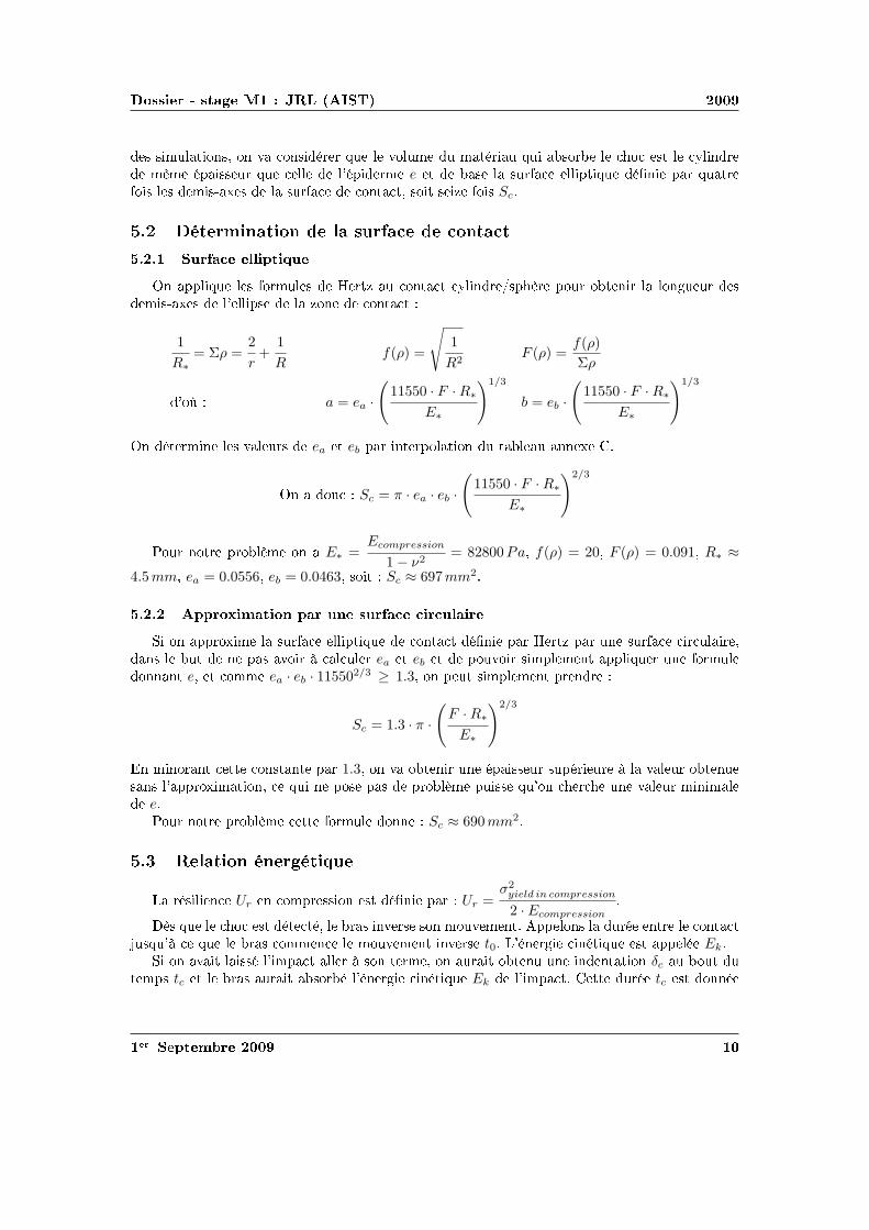
diamsssr st
rheartsstdiamshearts
r clubstspadesr
diamsssr st
rheartsstdiamshearts
r clubstspadesr
diamsssr st
clubstrs ①diamsr
Physical Properties
Thickness 0008rdquo (0203 mm)Length 775rdquo (197 mm)
optional 6rdquo (152 mm)trimmed 4rdquo (102 mm)lengths 2rdquo (51 mm)
Width 055rdquo (14 mm)Sensing Area 0375rdquo (953 mm) diameterConnector 3-pin Male Square Pin (center pin is inactive)Substrate Polyimide (ex Kapton)
Available Force Ranges (as tested with circuit shown)
HT201-L Low 0-30lb (0-133N)HT201-H High 0-100lb (0-445N)
In order to measure forces outside ofspecified ranges use recommended circuit and adjustdrive voltage andor reference resistance
Typical Performance
Linearity plusmn12 of full scaleRepeatability plusmn35 of full scaleHysteresis 36 of full scaleDrift 33 per log timeTemperature Range 15degF to 400degF (-9degC to 204degC)Output ChangeDegree F 016
Specifications based on pressures up to 500 psi and represent the average value throughout a range of temperatures up to 400degF
Actual size of sensor
Sensing
area
Recommended Circuit
r clubstspadesr
clubstrs t
Oslash0125 [32]
FUTEK MODEL FBB300
W I R I N G C O D E (WC1)+Excitation
RED BLACK-Excitation +Signal
GREEN-SignalWHITE
075 [191]
050 [127]
125 [318]
025 [64]
031 [79]
T
EXPOSED
ELEMENTS
+OUTPUT(TENSION)
(Previously FR1010)
EXPLODED ASSEMBLED
MCP01027
MCP01026
LOAD
EXAGGERATEDDEFLECTION
44510 0031 [076]FSH01454
FSH01456
FSH01455
40
20
178
89 0048 [122]
006 [152]
FSH01451
FSH01453
FSH01452
lbCAPACITY
STK
2
5
1
89
222
45
N
0015 [039]
0025 [064]
T
001 [028]
teacuter seacutetdiamsheartsheartseacute clubsdiamsr clubs
Saint-Gobain Korelreg K30-15 Soft Micro-cellular Polyurethane Foam
Categories Polymer Thermoplastic Polyurethane TP Thermoset Polyurethane TS Thermoset PolyurethaneFoam Unreinforced
MaterialNotes
Description The Korelreg series micro-cellular polyurethane foams are offered in a broad range ofproperties making them ideal for a variety of gasketing and energy absorption needs Korelregmicrocellular foams are categorized by degree of deflection force By varying the modulus anddensity Saint Gobain Performance Plastics has developed this series of materials that meets thedemands of design engineers today All Korel fians are available with an aggressive acrylic adhesiveon one side to facilitate placement Korel K30 foams are soft conformable low deflection urethanefoams offering excellent compression set resistance and low out-gassing that exceeds foggingrequirements K30 is ideal for openclose applications
FEATURESBENEFITS
Excellent compression set resistanceHighly resilient (will not collapse)Dissipates stressesResistant to moisture and most chemicalsConformable and flexible even in extreme environmental conditionsEasy to achieve intricate die-cut partsAggressive acrylic adhesive (optional) facilitates assemblyAvailable cast on to polyester film for stability and low deformation
Typical Applications Cellular telephones electrical enclosures electronic gasketing vibrationdamping cushioning acoustical control bumpers instrument panels spacersSpecification Notes Passes Fogging Test SAE-J 1756 3 hrs at 212degF (100degC) All data based on a025 inch test sample(Available in multiple thicknesses)Information provided by Saint Gobain Performance Products
Thermal Properties Metric English CommentsThermal Conductivity 00865 Wm-K 0600 BTU-inhr-ftsup2-degF ASTM E1530Maximum ServiceTemperature Air
700 degC 158 degF Constant use
121 degC 250 degF Intermittent Descriptive PropertiesStandard Color Black
Some of the values displayed above may have been converted from their original units andor rounded in order to display the information in a consistantformat Users requiring more precise data for scientific or engineering calculations can click on the property value to see the original value as well as rawconversions to equivalent units We advise that you only use the original value or one of its raw conversions in your calculations to minimize rounding errorWe also ask that you refer to MatWebs disclaimer and terms of use regarding this information Click here to view all the property values for this datasheet asthey were originally entered into MatWeb
diamsssr st
❱rs ea t eb hearts diamsheartstdiamshearts rtdiams F (ρ)
ρ ea eb ρ ea eb infin
r clubstspadesr
Combining Haptic Sensing with Safe Interaction
Martin Battaglia Laurent Blanchet Abderrahmane KheddarSuuji Kajita and Kazuhito Yokoi
Abstractmdash We propose a solution which combines hapticsensing with safe interaction at low cost Contact locations aremade through a flexible sheet of tactile binary switch matrixThis sheet covers the surface of a rigid bumper module assem-bled to the robotrsquos basic link through a distributed pressuresensing units Combination of location and force provides thehaptic sensing module The haptic system is covered with aflexible outer material which role is to absorb contact impactsand to cast local surface profile on which the robot can takesupport This overall system allows having a combined hapticsensing with safe and robust physical interaction with boththe environment and the human using active compliance Wediscuss the benefit of such a simple and modular concept andpresent how to design the cover material A simple prototypeis realized and experienced
I I NTRODUCTION
Haptic sensing and safe interaction with the environmentand humans are two challenging issues in robotics in generaland in humanoid robots in particular These issues are crucialand even interrelated when humanoid robots are allowed totake contact supports with entire body on any part of theenvironment This example highlights the importance for therobot to know where contacts occurred on its body and whatis the total force wrench applied on each of its links it alsobring to light the importance to have robust contact formationfor a stable whole-body motions support see a thoroughdiscussion of this example in [1]
Recent researches are tackling the problem of haptic sens-ing through bio-mimetic approaches (artificial skin) Theseapproaches are interesting and challenging several admirabletechnologies and designs have been proposed to build an ar-tificial sensing skin However we distinguish between hapticsensing that is used for whole-body motions interaction andclosed-loop task realization from that haptic sensing usedfor robot perception and acquisition of haptic knowledge orprecise dexterous manipulation There are also considerableworks in achieving human-robot safety collocated physicalhuman-robot interaction through various techniques that canbe gathered in two main categories active passive or hybridcompliance Several very sophisticated design and prototypes
This work was supported in part by the EC FP6 Contract No 034002wwwrobot-at-cweeu
M Battaglia and A Kheddar are with the Centre National dela Recherche Scientifique CNRS-UM2 LIRMM Montpellier Franceand with the CNRS-AIST JRL UMI3218CRT Tsukuba Japanbattagliakheddarlirmmfr
L Blanchet is with ENS Cachan France and with the CNRS-AIST JRLUMI3218CRT Tsukuba Japanblanchetcransorg
S Kajita and K Yokoi are with the Humanoid Research Groupof the Intelligent Systems Research Institute of the National Insti-tute of Advanced Industrial Science and Technology Tsukuba Japanskajitakazuhitoyokoiaistgojp
have been recently demonstrated with very impressive re-sults
Our work aims at designing a combined haptic sensing andactive safety interaction system which can cover the entirebody of the robot for whole body motion and at low cost Itwill be used for detecting locating and absorbing safely thecontacts and the collisions of both the (humanoid) robot andits surrounding Such a combined system is very useful for ahumanoid robot operating in a changing environment whereobjects and possibly human beings are moving The totalhumanoidrsquos cover surface is important enough for parameterssuch as cost weight and thickness to be critical
Fig 1 Exploded view of the whole design for an arm from left to rightthe robot links (dark) and the distributed pressure sensors(gray rings) thebumper the contact location tactile binary switches the compliant cover
Our approach is driven by practical viewpoints as willbe seen later on some researches have taken more or less asimilar path considering similar constraints We simply wenta bit further in our investigations to see how a combinedwhole-body haptic and safe interaction can be tackled witha pragmatic way for real usage and applicability We considerany link of the robot to be made of two main parts (i) theproper robot link and (ii) our system the later consists infour parts Fig 1 (ii) a simple shape bumper surrounding therobotrsquos link and attached to it through (i) distributed pressuresensor units (iii) a contact location sensor being a thinsheet of matrix tactile binary switches (in its simplest form)and which covers entirely the bumper its role is to providecontact locations (contact surfaces and their barycenter) and(iv) a compliant material (foam) covering the tactile sheetwhich role is to well cast the contacting surface and to absorbchocks at the contact spots
The first part of the paper discusses the overall conceptthe second part focuses on a computation tool allowing todetermine the characteristics of the compliant outer coverthe third part presents a preliminary proof-of-concept
II PROPOSEDSOLUTION
Our solution combines whole-body haptic sensing andsafety interaction function The requirements that drove ourapproach are summarized as follows
bull coverage of wide areas of robotrsquos links with minimumsignal processing latencies and data flow on the robotrsquosnetwork or bus
bull usage of a flexible outer cover to absorb impacts dueto desired or not desired contacts and to locally castsurface profile it can also be used for aesthetics
bull location on the robot of contact areas and measurementof force wrenches per link
bull modular quickly demountable interchangeable with aneasily maintenance and life cycle
bull not costly light and with reasonable thickness
We devised a modular system which allows combiningsimple technologies in a multilevel design described inFig 1 Starting from a bare robotrsquos link we attach to it a rigidsimple shaped cover (bumper) through distributed pressureunits which deformation measures the resultant force wrenchacting on the link Distributing pressure units on the linkis preferable to having a single location of force measureeg using a commercial 6dof force sensor Yet an optimaldistribution and location is to be found for each link byrestricting the number of the pressure units (if possible to6 or less) This part will be published in another paper
The bumper is covered by a flexible tactile sensing sheetsee Fig 1 Its role is to sample the contact spots on eachlink That is where contacts occur and for each contactan estimate of its area and barycenter Our choice wouldhave been to use flexible keyboards technology since itis simple mature and cheap enough But the switches aremechanical whereas capacitive switches may have superioradvantages Other options are possible In [2] a sensitiveskin is developed on the basis of single sided electrodeunits covered by a conductive rubber with a resistivity whichdepends on the applied pressure Their matrix tactile systemneeds one wire per taxel and could basically be used inour case In [3] a multi-contact detection sensor sheet basedon resistive measurement consists in two conductive plateseach in a discrete combination of parallel conductive bandsare separated by a pressure sensitive material that acts asan electrical insulator under no load but conduct electricitywhen pressure is applied The material is chosen for itselectric characteristics and the thickness being a result ofthe fabrication process If bended in a low curvature itcould be damaged The work by [4] uses the same physicalprinciple for measuring the pressure distribution but witha grid architecture what reduces the number of wires toone per line and one per column Using the same kind ofconductive rubber the system shown in [5] goes further in thereduction of the wires number by using electrical impedancetomography that allows measurement only on the borders ofthe skin to obtain pressure distribution and can basically beused in our design Since we consider pressure sensor unitsto have the resultant force wrench on each link quantifying
the pressure information is not necessary in our case That iswhy we can certainly make previous technologies simpler orthinner or make use of binary onoff switches It is what wedid for the proof-of-concept with putting a diode after eachswitch to avoid ghosting effect There are obviously severaladditional technologies which we did not mention not onlybecause of space but also because they are not mature enoughfor use We are however investigating capacitive switches
At this stage we have the choice between designing thetactile sensor with (i) thick resistive or capacitive foam sothat the tactile sensor could also absorb impacts or (ii) athin tactile sensor and a separate additional flexible coverto absorb impacts We decided to win the second choicefor many reasons Among which the freedom to design thesensor with optimal resolution using best of resistive and ca-pacitive material layers avoid using stretchable technologiesfor the tactile sensor since they compose the surface of thelink protect the sensor by its inner location possibility iebetween the bumper and the flexible cover design the coverwith esthetic shapes etc
Once the tactile sensor technology is decided it is coveredby a flexible material which role is to absorb impacts duringthe necessary time to detect it and react to it (active compli-ance) and also to cast well the surface to build robust whole-body motion supporting contacts This part is very importantand need to be carefully designed Authors in [6] consideredcriteria borrowed from human injury data and tested impactwith different materials Recent researches make use of datafrom crash-tests in automobile industry [7] But to our bestknowledge the model for mechanical characteristics and thethickness determination of the cover has not been thoroughlystudied This paper focuses on computation of the thicknessfor a given material or on characterizing the material bothunder constraints related to the issue of haptic sensing andsafe interaction We also study the influence of the flexiblecoverrsquos thickness and the resolution on the sensitivity of thetactile sheet
III F LEXIBLE COVERrsquo S CHARACTERISTICS
We based our characterization of the cover on the excellentreview of the impact problem performed by Stronge [8]We build a method for computing the material propertiesof a cover given a set of well defined constraints First wedefine a set of relations linking several parameters involvedin the characterization of the coverrsquos material Only after weexplain the algorithm which makes use of these relations inan interactive design process
Consider two bodiesB and Bprime for which the followingparameters can be defined The effective modulusElowast =[(
1minusν2B
)
Eminus1B +
(
1minusν2Bprime
)
Eminus1Bprime
]minus1where Ei is the Youngrsquos
modulus (Pa) andνi the Poissonrsquos ratio of the bodyi theeffective radiusRlowast =
[
Rminus1B +Rminus1
Bprime
]minus1whereRi is the local
radius of curvature of the bodyi (m) at the contact point theeffective massmlowast =
[
mminus1B +mminus1
Bprime
]minus1wheremi is the contact
projected mass of the bodyiThe collided bodyBprime is the obstacle and its mechanical
characteristics are considered known (worst case setting) We
want here to cover the colliding robot bodyB with a flexiblematerial whose goal is to absorb the impact during the timeneeded to detect and to react (computation of the activecompliance) which is a given time constraintτ (seconds)
A Impact model
In chapter 6 of [8] Stronge established the impact modelfor free colliding spherical bodies we followed similarcomputation steps for establishing an impact model thatwould apply for the system represented in Fig 2 It is a1dof robotic motorized link covered by elastic foam and forwhich we establish the impact model in the worst case iewhen it hits a rigid unmovable obstacle like a wall corner
G
C
v0
θ
d
l
x
y
O
Fig 2 Illustration of the prototype case study
In this simple case study C is the contact point G thecenter of mass O the origind the distance between thecontact point and the originl the distance between the centerof mass and the origin andθ the joint angle of the arm Thedynamic model for the arm is
Jθ +Mgl sinθ = uminusdF (1)
where J = mB12 (3R2
B + d2) + mBl2 is the moment of inertiau the motor torque andF = Ksδ32 the contact force withKs = 4
3ElowastR12lowast [8] The relationsθ = δ
d andθ minusθ0 = δd lead
toJd
δ +Mgl sin
(
θ0 +δd
)
= uminusdKsδ32 (2)
whereθ0 the angle of the arm at the contact Considering thatδ = δ dδ
dδ and the initial conditionsδ(0) =minusv0 andδ(0) = 0the integration of the previous equation gives
J2d
(δ2minus v20)minusMgld cos
(
θ0 +δd
)
= uδ minus2dKs
5δ52 (3)
When the compression phase ends att = tc the normalrelative velocity vanishes soδ = 0 δ = δc and asδ ltlt dcos
(
θ0 + δd
)
asymp cosθ0 The eq (3) gives us the expressionof the compression time
tc =int δc
0
(
v20 +
2d2
JMgl cosθ0 +
2duδJ
minus4Ksd2
5Jδ52
)minus12
dδ(4)
and becomes
J2d
v20 +Mgld cos(θ0) = minusuδc +
2dKs
5δ52
c (5)
None of these two equations has an analytical solution sowe can not find an analytical expression ofElowast in functionof tc as done in the Strongersquos example
B Yield aspect
Whatever material we choose we will forbid to reach theplastic domain during compression so that the impact doesnot become rigid This second part is in quasi-static andthe results depend of the material and the geometry not ofthe mechanical structure and the dynamics of the robot Theeffective modulus gives us the ratioEB
1minusν2B what we use to
choose a material and so to obtainYB the yield stress ofthe bodyB (Pa) The transition contact pressure between theelastic and the plastic domains ispY = vYYB It occurs forthe bodyB at the indentation limit for elastic deformationδY obtained from
pY
YB= vY =
4Elowast
3πYB
radic
δY
Rlowast(6)
where the ratiovY depends on the geometry of the contact(for example for a contact between two spheresvY = 11and between a cylinder and a planevY = 15) This leads tothe non-dimensional indentationδY
Rlowastrequired to initiate yield
a material property
δY
Rlowast=
(
3π4
)2(
vYYB
Elowast
)2
(7)
We do not make use of eq (7) explicitly it is checked at eachstep of the design process to ensure that the indentation donot reach the yield limit
C Skin thickness for energy absorbing
Let Ur be the material resilience which defines the energythat the material can elastically absorb per unit of volumeWe know that a spherecylinder contact (our case study) iselliptic and can be expressed according to Hertzrsquos contact
theory asSc = 13π(
FRlowastElowast
)23 Finite element simulations
show that volume absorbing the energy can be approximatedby a cylinder with a surface 4 times bigger in both dimen-sions than the contact area ie 16Sc the thicknesse beingits height
Considering the energy absorption rate linear leads to theenergy to be absorbed by the skinEn = Ek middot (t0tc) withtc the time that would have been required if the skin hadto absorb all the impact as defined beforeW is the workdone by the contact effort and we state that all of the energyis transmitted to the material (again worst case scenario)so
W = En Strongersquos work [8] gives usWElowastR3
lowast= 8
15
(
δRlowast
)52thus
the effort F =(
(
815
)2E3
k E2lowastRlowast
)15
The resilienceUr is given byUr = YB22EB
Considering thatUre16Sc = En and thatEk = 1
2mv20 we have
e =m35 middot v65
0 middot (t0tc)
84middotUr middot(
R2lowastEminus1
lowast)615
(8)
D Sensitivity of the sensor
We will use a sensor build as a square matrix of switchAs this sensor does discrete contact detection it is importantto estimate the sensitivity of the sensor ie the necessarycontact force to be detected considering the thickness andthe resolution of the matrix ie distance between twoswitches
We based our study on [9] (Chapt 3) We considera semi-infinite homogeneous linear elastic incompressible(ie with a Poisson ratio of 05) material on which a normalpunctual forceF is applied We defineσz the stress in thenormal direction of a given point This model states
F =2σzπ(x2 + y2 + z2)52
3z3 (9)
where (xyz) are the coordinates of a point relative to thecontact point the contact point being the origin In the worstcase ie the contact point being equidistant of each switchwe set the point on the center of the switch There we haveσz = Fs
S whereFs is the necessary force to press the switchuntil the electrical contact andS the surface of the contactbetween the switch and the coverx2 + y2 = d2
2 d being theresolution of the matrix andz = e e being the thickness ofthe skin We obtain
F =2Fsπ( d2
2 + e2)52
3Se3 (10)
Fig 3 Schematic of the algorithm
E Algorithm for material thickness and other parametersdetermination
Now considering a given situation of impact (geometricalinertial and impact parameters known) and a given sensor
technology (Fs and S known) we determine the unknownparameters for designing the cover materialEB being theYoung moduluse the thickness andρ the density of theskin andF the minimal detectable force by the sensor anddthe resolution of the sensor We can have some constrains onparameters set by external factors for instanced lt dmax andF lt Fmax or e lt emax Those constraints must be checked atevery step of the algorithm If not we have to reconsider theconstraints or to make different choices namely a differentmaterial
IV PROTOTYPE
We devised a 1dof motorized arm as a proof-of-concept toperform experiments prior to a first prototype It is made ofa stainless tube attached to the force sensor which in turnsis linked to a DC motor We also realized the tactile matrixand the polyurethane foam plate on it see Fig 4
Fig 4 Assembled prototype
A Design
We took Elastomeric foams as the cover material Thismaterial can extend more than 100 in a classical tractiontest and remain in the elastic domain Sensorsrsquo screeningsand control computation latencies sum tot0 asymp 6ms (we setit to τ = 8ms) The characteristics of arm aremB = 06kgRB = 38mm l = 150mm andd = 200mm The initial speedis v0 = 04msminus1 and the contact angle isθ0 = 0rad Theother constants areRBprime = 38mm andg = 981msminus2
Our algorithm gives the following solutionEB =365105Pa andδc = 32mm We found a material fittingthis characteristic thanks to the Matweb database themicro-cellular polyurethane foam (Young modulus isE =345 105Pa yield stress isYB = 841105Pa) We changedsome values of our device to increase safetym = 2kg andv0 = 15msminus1 and use the characteristics of the chosenmaterial in eq (8) we obtained the following resultsUr = 4791Jmminus3 and e = 790mm We found micro-cellularpolyurethane foam in 5mm and 10mm thick plate so we usedboth as a good approximation of the results of the modeldepending of the degree of safety
In case of sudden contact (switch on) we stop the ongoingmotion and reverse it up to the contact detection We alsomade an active compliance using the force sensor Wedecided of a limit the torque to 3Nm for couple this valuebeing the rated range of our sensor which corresponds to
15N for the contact effort the distance between the sensorand the contact being 20cm
B Tactile sheet prototype
We designed a simple matrix of commercial onoff me-chanical small switches combined with a force sensormounted between the link and the actuator it has 1cmresolution spacing The keyboard pattern leads to a reducednumber of wires that allows a direct connection to the IOcard we used for data processing In case of an extensionof the matrix ie an increase of the number of wiresmultiplexing is necessary
Main computations are done at the same time to op-timize the contact detection time we used a FPGA chipprogrammed with VHDL language These chip and languageare particularly designed for task parallelization The twomain tasks are (i) to identify contact zones ie to gatheradjacent pressed switches in the same contact set and (ii) tocompute the area and the barycenter of each contact zone
C Experiment
We conducted experiments to assess the principle of thesystem ie detecting the contact and the subsequent in themotionrsquos direction We also evaluated the efforts resultingfrom the contact The experimentation consists in movingthe arm into an obstacle A human arm is used as a suddenobstacle once detected the controller reverses the motionuntil the contact is resolved and finally slowing down untilits stops
arm
foam
force sensor
motor
gear and
coupling
power
Fig 5 Experimental set-up
We led the experiment with two thicknesses of the flexiblefoam cover 5mm and 10mm the Figs 6 and 7 show theresults of the experiment for the 5mm thick cover Theinfluence of the thickness is studied further The Fig 6represents the evolution of the angular speed of the armand the Fig 7 the evolution of the torque between the armand the motor
The Fig 6 illustrates that the system achieves the previ-ously described behavior The Fig 7 shows that the contactis not instantaneously detected but that the torque ie thecontact force has to reach a certain value for the electricalcontact in a switch to be realized
-150
-50
0
50
150
250
Speed (degs)
contact
20 40 60 80
Time (ms)
20 40 60 80
Time (ms)
Fig 6 Measurement of the speed during the experiment
05
1
15
2
25
Time (ms)
Torque (Nm)
0 20 40 60 80
1
100
contact
Fig 7 Measurement of the torque during the experiment
The measured values are 23Nm for the torque so 12Nfor the contact force the distance between the contact pointand the torque sensor being 20cm
We noted that if the speed starts decreasing as soon as thecontact is detected it stays positive for around 5ms whenthe torque immediately decreases what could be surprisingconsidering that the compression continues as long as thespeed is positive The explanation of this phenomenon isthat the measured torque is between the motor and the armso when the contact is detected the reference for the motorimmediately changes and the motor tries to go back whenthe mechanical inertia of the arm maintains the speed positivefor a short time Indeed the mechanical inertia is higher thanthe electrical one It is not really significant in this casebutthat point must be kept in mind and taken into account forthe next developments of the system
For our the tactile system we devised the characteristicsof a unit switch areFm = 1N and S = 126 10minus6m2 0 ltd lt 0005
radic2m andz = 0005m which leads the graphics in
Fig 8As we can see on Fig 8 and from the equation (9)
the necessary force to initiate detection grows as a sixdegree polynomial toFc = 65N for d = 0005
radic2 ie at the
Fig 8 Contact force in function of the distance forz = 5mm and of thethickness ford = 5
radic2mm
maximum possible distance from a switchIf we know the force by measurement as in our ex-
periment described above we can easily invert this modelto evaluate the distance between the contact point and theswitch In our example we measuredFc = 12N so the valueof the distance isd = 00036m
We can also see the influence of thickness on the necessarycontact force at the farthest point of any switch ford =0005
radic2m It shows that in this particular case the minimal
contact force isFc = 45N equivalent to a 85Nm torque atthe central point of the force sensor Considering that thesecurity limit for our force sensor is 3Nm which stops thesystem when reached the maximum contact force acceptableis therefore 15N It is not possible for it to be detected atd =0005
radic2m as the Fig 8 showed From the Fig 8 and from
the equation (9) in the case of a 5mm cover we find thatthe maximum distance isd = 42mm It means a definitionof 59mm asd is the half-diagonal of the square made bythe 4 switches around the contact point
Here this sensitivity study suggests to us to reconsiderour initial choice of definition to ensure contact detectionconsidering the physical limits of the prototype
D Linear elastic hypothesis
We run compression tests on our material which led tothe results shown on the Fig 9 This figure shows that thematerial has an elastic linear behavior up to at least 30N forboth thicknesses The correlation coefficient being superiorto 099 Therefore since the maximum measured force inour experiment is 12N the material remains in the elasticlinear domain and the hypothesis made for all computationshold
V CONCLUSION
We proposed a simple design to combine at low cost hapticsensing with safe interaction and robust contact formationthrough outer cover compliance This system appears to bemodular enough to be envisaged as a potential solution toembed haptic sensing and compliance to humanoid robotsWe devised a simple one degree of freedom prototype whichassesses the feasibility of the idea We also proposed amethod to design the cover and proved it detect collisions andreact according to the strategy envisaged for the control thehaptic function combines a flexible sheet of onoff switches
Fig 9 Deformation in function of the force for both 5mm and 10mmthicknesses
with a force sensor that could be embedded with a bumpermechanism It proves the validity of this principle of a tactilesoft cover to introduce a safety against collision for the robotand its environment Furthermore the sensitivity study givesus valuable information about the possible thickness anddefinition considering a limit contact force and a certainkind of switch
The next step of this work will be to design on the basisof this principle a better sensor extensible to a larger areaand able to be installed on a real robot and to solve theproblem of sensing at the area of the jointrsquos of the robot
REFERENCES
[1] A Kheddar and A Escande ldquoChallenges in contact-support planningfor acyclic motion of humanoids and androidsrdquo in39th InternationalSymposium on Robotics Seoul Korea October 15-17 2008 pp 740ndash745
[2] D Goeger K Weiss C Burghart and H Woern ldquoSensitive skinfor a humanoid robotrdquo inHuman-Centered Robotic Systems MunichGermany October 6-7 2006 pp 115ndash120
[3] V Duchaine N Lauzier M Baril M-A Lacasse and C Gosselin ldquoAflexible robot skin for safe physical human robot interactionrdquo in IEEEInternational Conference on Robotics and Automation Kobe JapanMay 12-17 2009 pp 3676ndash3681
[4] X Lamy F Colledani F Geffard Y Measson and G Morel ldquoRoboticskin structure and performances for industrial robot comanipulationrdquo inIEEEASME International Conference on Advanced Intelligent Mecha-tronics Singapore July 14-17 2009 pp 427ndash432
[5] A Nagakubo H Alirezaei and Y Kuniyoshi ldquoA deformable anddeformation sensitive tactile distribution sensorrdquo inIEEE InternationalConference on Robotics and Biomimetics Sanya China December 15-18 2007 pp 1301ndash1308
[6] T Sugaiwa H Iwata and S Sugano ldquoShock absorbing skin designfor human-symbiotic robot at the worst case collisionrdquo inIEEE-RAS International Conference on Humanoid Robots Daejeon KoreaDecember 1-3 2008 pp 481ndash486
[7] S Haddadin A Albu-Schaeffer M Frommberger J Rossmann andG Hirzinger ldquoThe DLR crash report towards a standard crash-testingprotocol for robot safety - part I and IIrdquo inIEEE InternationalConference on Robotics and Automation Kobe Japan May 12-17 2009pp 272ndash287
[8] W J StrongeImpact mechanics Cambridge University Press 2000[9] K L JohnsonContact mechanics Cambridge University Press 1985
- I Preacutesentation
-
- Preacutesentation du laboratoire
- Preacutesentation du travail effectueacute
-
- II Conception de la combinaison haptique
-
- Objet de lavant-projet de combinaison
- Conception davant projet de la carapace haptique
-
- Cahier des charges
- Deacutetermination du torseur mesureacute
- Capteurs
-
- Dimensionnement de leacutepaisseur de leacutepiderme
-
- Approximation du volume absorbant le choc
- Deacutetermination de la surface de contact
-
- Surface elliptique
- Approximation par une surface circulaire
-
- Relation eacutenergeacutetique
- Effort au contact
- Eacutepaisseur de la peau
-
- Surface ellipsoiumlde
- Approximation
-
- III Conclusion
-
- Perspectives
-
- Organisation ISRI
- Valeurs de ea et de eb en fonction du ratio F()
-

diamsssr st
rheartsstdiamshearts
r clubstspadesr
diamsssr st
clubstrs ①diamsr
Physical Properties
Thickness 0008rdquo (0203 mm)Length 775rdquo (197 mm)
optional 6rdquo (152 mm)trimmed 4rdquo (102 mm)lengths 2rdquo (51 mm)
Width 055rdquo (14 mm)Sensing Area 0375rdquo (953 mm) diameterConnector 3-pin Male Square Pin (center pin is inactive)Substrate Polyimide (ex Kapton)
Available Force Ranges (as tested with circuit shown)
HT201-L Low 0-30lb (0-133N)HT201-H High 0-100lb (0-445N)
In order to measure forces outside ofspecified ranges use recommended circuit and adjustdrive voltage andor reference resistance
Typical Performance
Linearity plusmn12 of full scaleRepeatability plusmn35 of full scaleHysteresis 36 of full scaleDrift 33 per log timeTemperature Range 15degF to 400degF (-9degC to 204degC)Output ChangeDegree F 016
Specifications based on pressures up to 500 psi and represent the average value throughout a range of temperatures up to 400degF
Actual size of sensor
Sensing
area
Recommended Circuit
r clubstspadesr
clubstrs t
Oslash0125 [32]
FUTEK MODEL FBB300
W I R I N G C O D E (WC1)+Excitation
RED BLACK-Excitation +Signal
GREEN-SignalWHITE
075 [191]
050 [127]
125 [318]
025 [64]
031 [79]
T
EXPOSED
ELEMENTS
+OUTPUT(TENSION)
(Previously FR1010)
EXPLODED ASSEMBLED
MCP01027
MCP01026
LOAD
EXAGGERATEDDEFLECTION
44510 0031 [076]FSH01454
FSH01456
FSH01455
40
20
178
89 0048 [122]
006 [152]
FSH01451
FSH01453
FSH01452
lbCAPACITY
STK
2
5
1
89
222
45
N
0015 [039]
0025 [064]
T
001 [028]
teacuter seacutetdiamsheartsheartseacute clubsdiamsr clubs
Saint-Gobain Korelreg K30-15 Soft Micro-cellular Polyurethane Foam
Categories Polymer Thermoplastic Polyurethane TP Thermoset Polyurethane TS Thermoset PolyurethaneFoam Unreinforced
MaterialNotes
Description The Korelreg series micro-cellular polyurethane foams are offered in a broad range ofproperties making them ideal for a variety of gasketing and energy absorption needs Korelregmicrocellular foams are categorized by degree of deflection force By varying the modulus anddensity Saint Gobain Performance Plastics has developed this series of materials that meets thedemands of design engineers today All Korel fians are available with an aggressive acrylic adhesiveon one side to facilitate placement Korel K30 foams are soft conformable low deflection urethanefoams offering excellent compression set resistance and low out-gassing that exceeds foggingrequirements K30 is ideal for openclose applications
FEATURESBENEFITS
Excellent compression set resistanceHighly resilient (will not collapse)Dissipates stressesResistant to moisture and most chemicalsConformable and flexible even in extreme environmental conditionsEasy to achieve intricate die-cut partsAggressive acrylic adhesive (optional) facilitates assemblyAvailable cast on to polyester film for stability and low deformation
Typical Applications Cellular telephones electrical enclosures electronic gasketing vibrationdamping cushioning acoustical control bumpers instrument panels spacersSpecification Notes Passes Fogging Test SAE-J 1756 3 hrs at 212degF (100degC) All data based on a025 inch test sample(Available in multiple thicknesses)Information provided by Saint Gobain Performance Products
Thermal Properties Metric English CommentsThermal Conductivity 00865 Wm-K 0600 BTU-inhr-ftsup2-degF ASTM E1530Maximum ServiceTemperature Air
700 degC 158 degF Constant use
121 degC 250 degF Intermittent Descriptive PropertiesStandard Color Black
Some of the values displayed above may have been converted from their original units andor rounded in order to display the information in a consistantformat Users requiring more precise data for scientific or engineering calculations can click on the property value to see the original value as well as rawconversions to equivalent units We advise that you only use the original value or one of its raw conversions in your calculations to minimize rounding errorWe also ask that you refer to MatWebs disclaimer and terms of use regarding this information Click here to view all the property values for this datasheet asthey were originally entered into MatWeb
diamsssr st
❱rs ea t eb hearts diamsheartstdiamshearts rtdiams F (ρ)
ρ ea eb ρ ea eb infin
r clubstspadesr
Combining Haptic Sensing with Safe Interaction
Martin Battaglia Laurent Blanchet Abderrahmane KheddarSuuji Kajita and Kazuhito Yokoi
Abstractmdash We propose a solution which combines hapticsensing with safe interaction at low cost Contact locations aremade through a flexible sheet of tactile binary switch matrixThis sheet covers the surface of a rigid bumper module assem-bled to the robotrsquos basic link through a distributed pressuresensing units Combination of location and force provides thehaptic sensing module The haptic system is covered with aflexible outer material which role is to absorb contact impactsand to cast local surface profile on which the robot can takesupport This overall system allows having a combined hapticsensing with safe and robust physical interaction with boththe environment and the human using active compliance Wediscuss the benefit of such a simple and modular concept andpresent how to design the cover material A simple prototypeis realized and experienced
I I NTRODUCTION
Haptic sensing and safe interaction with the environmentand humans are two challenging issues in robotics in generaland in humanoid robots in particular These issues are crucialand even interrelated when humanoid robots are allowed totake contact supports with entire body on any part of theenvironment This example highlights the importance for therobot to know where contacts occurred on its body and whatis the total force wrench applied on each of its links it alsobring to light the importance to have robust contact formationfor a stable whole-body motions support see a thoroughdiscussion of this example in [1]
Recent researches are tackling the problem of haptic sens-ing through bio-mimetic approaches (artificial skin) Theseapproaches are interesting and challenging several admirabletechnologies and designs have been proposed to build an ar-tificial sensing skin However we distinguish between hapticsensing that is used for whole-body motions interaction andclosed-loop task realization from that haptic sensing usedfor robot perception and acquisition of haptic knowledge orprecise dexterous manipulation There are also considerableworks in achieving human-robot safety collocated physicalhuman-robot interaction through various techniques that canbe gathered in two main categories active passive or hybridcompliance Several very sophisticated design and prototypes
This work was supported in part by the EC FP6 Contract No 034002wwwrobot-at-cweeu
M Battaglia and A Kheddar are with the Centre National dela Recherche Scientifique CNRS-UM2 LIRMM Montpellier Franceand with the CNRS-AIST JRL UMI3218CRT Tsukuba Japanbattagliakheddarlirmmfr
L Blanchet is with ENS Cachan France and with the CNRS-AIST JRLUMI3218CRT Tsukuba Japanblanchetcransorg
S Kajita and K Yokoi are with the Humanoid Research Groupof the Intelligent Systems Research Institute of the National Insti-tute of Advanced Industrial Science and Technology Tsukuba Japanskajitakazuhitoyokoiaistgojp
have been recently demonstrated with very impressive re-sults
Our work aims at designing a combined haptic sensing andactive safety interaction system which can cover the entirebody of the robot for whole body motion and at low cost Itwill be used for detecting locating and absorbing safely thecontacts and the collisions of both the (humanoid) robot andits surrounding Such a combined system is very useful for ahumanoid robot operating in a changing environment whereobjects and possibly human beings are moving The totalhumanoidrsquos cover surface is important enough for parameterssuch as cost weight and thickness to be critical
Fig 1 Exploded view of the whole design for an arm from left to rightthe robot links (dark) and the distributed pressure sensors(gray rings) thebumper the contact location tactile binary switches the compliant cover
Our approach is driven by practical viewpoints as willbe seen later on some researches have taken more or less asimilar path considering similar constraints We simply wenta bit further in our investigations to see how a combinedwhole-body haptic and safe interaction can be tackled witha pragmatic way for real usage and applicability We considerany link of the robot to be made of two main parts (i) theproper robot link and (ii) our system the later consists infour parts Fig 1 (ii) a simple shape bumper surrounding therobotrsquos link and attached to it through (i) distributed pressuresensor units (iii) a contact location sensor being a thinsheet of matrix tactile binary switches (in its simplest form)and which covers entirely the bumper its role is to providecontact locations (contact surfaces and their barycenter) and(iv) a compliant material (foam) covering the tactile sheetwhich role is to well cast the contacting surface and to absorbchocks at the contact spots
The first part of the paper discusses the overall conceptthe second part focuses on a computation tool allowing todetermine the characteristics of the compliant outer coverthe third part presents a preliminary proof-of-concept
II PROPOSEDSOLUTION
Our solution combines whole-body haptic sensing andsafety interaction function The requirements that drove ourapproach are summarized as follows
bull coverage of wide areas of robotrsquos links with minimumsignal processing latencies and data flow on the robotrsquosnetwork or bus
bull usage of a flexible outer cover to absorb impacts dueto desired or not desired contacts and to locally castsurface profile it can also be used for aesthetics
bull location on the robot of contact areas and measurementof force wrenches per link
bull modular quickly demountable interchangeable with aneasily maintenance and life cycle
bull not costly light and with reasonable thickness
We devised a modular system which allows combiningsimple technologies in a multilevel design described inFig 1 Starting from a bare robotrsquos link we attach to it a rigidsimple shaped cover (bumper) through distributed pressureunits which deformation measures the resultant force wrenchacting on the link Distributing pressure units on the linkis preferable to having a single location of force measureeg using a commercial 6dof force sensor Yet an optimaldistribution and location is to be found for each link byrestricting the number of the pressure units (if possible to6 or less) This part will be published in another paper
The bumper is covered by a flexible tactile sensing sheetsee Fig 1 Its role is to sample the contact spots on eachlink That is where contacts occur and for each contactan estimate of its area and barycenter Our choice wouldhave been to use flexible keyboards technology since itis simple mature and cheap enough But the switches aremechanical whereas capacitive switches may have superioradvantages Other options are possible In [2] a sensitiveskin is developed on the basis of single sided electrodeunits covered by a conductive rubber with a resistivity whichdepends on the applied pressure Their matrix tactile systemneeds one wire per taxel and could basically be used inour case In [3] a multi-contact detection sensor sheet basedon resistive measurement consists in two conductive plateseach in a discrete combination of parallel conductive bandsare separated by a pressure sensitive material that acts asan electrical insulator under no load but conduct electricitywhen pressure is applied The material is chosen for itselectric characteristics and the thickness being a result ofthe fabrication process If bended in a low curvature itcould be damaged The work by [4] uses the same physicalprinciple for measuring the pressure distribution but witha grid architecture what reduces the number of wires toone per line and one per column Using the same kind ofconductive rubber the system shown in [5] goes further in thereduction of the wires number by using electrical impedancetomography that allows measurement only on the borders ofthe skin to obtain pressure distribution and can basically beused in our design Since we consider pressure sensor unitsto have the resultant force wrench on each link quantifying
the pressure information is not necessary in our case That iswhy we can certainly make previous technologies simpler orthinner or make use of binary onoff switches It is what wedid for the proof-of-concept with putting a diode after eachswitch to avoid ghosting effect There are obviously severaladditional technologies which we did not mention not onlybecause of space but also because they are not mature enoughfor use We are however investigating capacitive switches
At this stage we have the choice between designing thetactile sensor with (i) thick resistive or capacitive foam sothat the tactile sensor could also absorb impacts or (ii) athin tactile sensor and a separate additional flexible coverto absorb impacts We decided to win the second choicefor many reasons Among which the freedom to design thesensor with optimal resolution using best of resistive and ca-pacitive material layers avoid using stretchable technologiesfor the tactile sensor since they compose the surface of thelink protect the sensor by its inner location possibility iebetween the bumper and the flexible cover design the coverwith esthetic shapes etc
Once the tactile sensor technology is decided it is coveredby a flexible material which role is to absorb impacts duringthe necessary time to detect it and react to it (active compli-ance) and also to cast well the surface to build robust whole-body motion supporting contacts This part is very importantand need to be carefully designed Authors in [6] consideredcriteria borrowed from human injury data and tested impactwith different materials Recent researches make use of datafrom crash-tests in automobile industry [7] But to our bestknowledge the model for mechanical characteristics and thethickness determination of the cover has not been thoroughlystudied This paper focuses on computation of the thicknessfor a given material or on characterizing the material bothunder constraints related to the issue of haptic sensing andsafe interaction We also study the influence of the flexiblecoverrsquos thickness and the resolution on the sensitivity of thetactile sheet
III F LEXIBLE COVERrsquo S CHARACTERISTICS
We based our characterization of the cover on the excellentreview of the impact problem performed by Stronge [8]We build a method for computing the material propertiesof a cover given a set of well defined constraints First wedefine a set of relations linking several parameters involvedin the characterization of the coverrsquos material Only after weexplain the algorithm which makes use of these relations inan interactive design process
Consider two bodiesB and Bprime for which the followingparameters can be defined The effective modulusElowast =[(
1minusν2B
)
Eminus1B +
(
1minusν2Bprime
)
Eminus1Bprime
]minus1where Ei is the Youngrsquos
modulus (Pa) andνi the Poissonrsquos ratio of the bodyi theeffective radiusRlowast =
[
Rminus1B +Rminus1
Bprime
]minus1whereRi is the local
radius of curvature of the bodyi (m) at the contact point theeffective massmlowast =
[
mminus1B +mminus1
Bprime
]minus1wheremi is the contact
projected mass of the bodyiThe collided bodyBprime is the obstacle and its mechanical
characteristics are considered known (worst case setting) We
want here to cover the colliding robot bodyB with a flexiblematerial whose goal is to absorb the impact during the timeneeded to detect and to react (computation of the activecompliance) which is a given time constraintτ (seconds)
A Impact model
In chapter 6 of [8] Stronge established the impact modelfor free colliding spherical bodies we followed similarcomputation steps for establishing an impact model thatwould apply for the system represented in Fig 2 It is a1dof robotic motorized link covered by elastic foam and forwhich we establish the impact model in the worst case iewhen it hits a rigid unmovable obstacle like a wall corner
G
C
v0
θ
d
l
x
y
O
Fig 2 Illustration of the prototype case study
In this simple case study C is the contact point G thecenter of mass O the origind the distance between thecontact point and the originl the distance between the centerof mass and the origin andθ the joint angle of the arm Thedynamic model for the arm is
Jθ +Mgl sinθ = uminusdF (1)
where J = mB12 (3R2
B + d2) + mBl2 is the moment of inertiau the motor torque andF = Ksδ32 the contact force withKs = 4
3ElowastR12lowast [8] The relationsθ = δ
d andθ minusθ0 = δd lead
toJd
δ +Mgl sin
(
θ0 +δd
)
= uminusdKsδ32 (2)
whereθ0 the angle of the arm at the contact Considering thatδ = δ dδ
dδ and the initial conditionsδ(0) =minusv0 andδ(0) = 0the integration of the previous equation gives
J2d
(δ2minus v20)minusMgld cos
(
θ0 +δd
)
= uδ minus2dKs
5δ52 (3)
When the compression phase ends att = tc the normalrelative velocity vanishes soδ = 0 δ = δc and asδ ltlt dcos
(
θ0 + δd
)
asymp cosθ0 The eq (3) gives us the expressionof the compression time
tc =int δc
0
(
v20 +
2d2
JMgl cosθ0 +
2duδJ
minus4Ksd2
5Jδ52
)minus12
dδ(4)
and becomes
J2d
v20 +Mgld cos(θ0) = minusuδc +
2dKs
5δ52
c (5)
None of these two equations has an analytical solution sowe can not find an analytical expression ofElowast in functionof tc as done in the Strongersquos example
B Yield aspect
Whatever material we choose we will forbid to reach theplastic domain during compression so that the impact doesnot become rigid This second part is in quasi-static andthe results depend of the material and the geometry not ofthe mechanical structure and the dynamics of the robot Theeffective modulus gives us the ratioEB
1minusν2B what we use to
choose a material and so to obtainYB the yield stress ofthe bodyB (Pa) The transition contact pressure between theelastic and the plastic domains ispY = vYYB It occurs forthe bodyB at the indentation limit for elastic deformationδY obtained from
pY
YB= vY =
4Elowast
3πYB
radic
δY
Rlowast(6)
where the ratiovY depends on the geometry of the contact(for example for a contact between two spheresvY = 11and between a cylinder and a planevY = 15) This leads tothe non-dimensional indentationδY
Rlowastrequired to initiate yield
a material property
δY
Rlowast=
(
3π4
)2(
vYYB
Elowast
)2
(7)
We do not make use of eq (7) explicitly it is checked at eachstep of the design process to ensure that the indentation donot reach the yield limit
C Skin thickness for energy absorbing
Let Ur be the material resilience which defines the energythat the material can elastically absorb per unit of volumeWe know that a spherecylinder contact (our case study) iselliptic and can be expressed according to Hertzrsquos contact
theory asSc = 13π(
FRlowastElowast
)23 Finite element simulations
show that volume absorbing the energy can be approximatedby a cylinder with a surface 4 times bigger in both dimen-sions than the contact area ie 16Sc the thicknesse beingits height
Considering the energy absorption rate linear leads to theenergy to be absorbed by the skinEn = Ek middot (t0tc) withtc the time that would have been required if the skin hadto absorb all the impact as defined beforeW is the workdone by the contact effort and we state that all of the energyis transmitted to the material (again worst case scenario)so
W = En Strongersquos work [8] gives usWElowastR3
lowast= 8
15
(
δRlowast
)52thus
the effort F =(
(
815
)2E3
k E2lowastRlowast
)15
The resilienceUr is given byUr = YB22EB
Considering thatUre16Sc = En and thatEk = 1
2mv20 we have
e =m35 middot v65
0 middot (t0tc)
84middotUr middot(
R2lowastEminus1
lowast)615
(8)
D Sensitivity of the sensor
We will use a sensor build as a square matrix of switchAs this sensor does discrete contact detection it is importantto estimate the sensitivity of the sensor ie the necessarycontact force to be detected considering the thickness andthe resolution of the matrix ie distance between twoswitches
We based our study on [9] (Chapt 3) We considera semi-infinite homogeneous linear elastic incompressible(ie with a Poisson ratio of 05) material on which a normalpunctual forceF is applied We defineσz the stress in thenormal direction of a given point This model states
F =2σzπ(x2 + y2 + z2)52
3z3 (9)
where (xyz) are the coordinates of a point relative to thecontact point the contact point being the origin In the worstcase ie the contact point being equidistant of each switchwe set the point on the center of the switch There we haveσz = Fs
S whereFs is the necessary force to press the switchuntil the electrical contact andS the surface of the contactbetween the switch and the coverx2 + y2 = d2
2 d being theresolution of the matrix andz = e e being the thickness ofthe skin We obtain
F =2Fsπ( d2
2 + e2)52
3Se3 (10)
Fig 3 Schematic of the algorithm
E Algorithm for material thickness and other parametersdetermination
Now considering a given situation of impact (geometricalinertial and impact parameters known) and a given sensor
technology (Fs and S known) we determine the unknownparameters for designing the cover materialEB being theYoung moduluse the thickness andρ the density of theskin andF the minimal detectable force by the sensor anddthe resolution of the sensor We can have some constrains onparameters set by external factors for instanced lt dmax andF lt Fmax or e lt emax Those constraints must be checked atevery step of the algorithm If not we have to reconsider theconstraints or to make different choices namely a differentmaterial
IV PROTOTYPE
We devised a 1dof motorized arm as a proof-of-concept toperform experiments prior to a first prototype It is made ofa stainless tube attached to the force sensor which in turnsis linked to a DC motor We also realized the tactile matrixand the polyurethane foam plate on it see Fig 4
Fig 4 Assembled prototype
A Design
We took Elastomeric foams as the cover material Thismaterial can extend more than 100 in a classical tractiontest and remain in the elastic domain Sensorsrsquo screeningsand control computation latencies sum tot0 asymp 6ms (we setit to τ = 8ms) The characteristics of arm aremB = 06kgRB = 38mm l = 150mm andd = 200mm The initial speedis v0 = 04msminus1 and the contact angle isθ0 = 0rad Theother constants areRBprime = 38mm andg = 981msminus2
Our algorithm gives the following solutionEB =365105Pa andδc = 32mm We found a material fittingthis characteristic thanks to the Matweb database themicro-cellular polyurethane foam (Young modulus isE =345 105Pa yield stress isYB = 841105Pa) We changedsome values of our device to increase safetym = 2kg andv0 = 15msminus1 and use the characteristics of the chosenmaterial in eq (8) we obtained the following resultsUr = 4791Jmminus3 and e = 790mm We found micro-cellularpolyurethane foam in 5mm and 10mm thick plate so we usedboth as a good approximation of the results of the modeldepending of the degree of safety
In case of sudden contact (switch on) we stop the ongoingmotion and reverse it up to the contact detection We alsomade an active compliance using the force sensor Wedecided of a limit the torque to 3Nm for couple this valuebeing the rated range of our sensor which corresponds to
15N for the contact effort the distance between the sensorand the contact being 20cm
B Tactile sheet prototype
We designed a simple matrix of commercial onoff me-chanical small switches combined with a force sensormounted between the link and the actuator it has 1cmresolution spacing The keyboard pattern leads to a reducednumber of wires that allows a direct connection to the IOcard we used for data processing In case of an extensionof the matrix ie an increase of the number of wiresmultiplexing is necessary
Main computations are done at the same time to op-timize the contact detection time we used a FPGA chipprogrammed with VHDL language These chip and languageare particularly designed for task parallelization The twomain tasks are (i) to identify contact zones ie to gatheradjacent pressed switches in the same contact set and (ii) tocompute the area and the barycenter of each contact zone
C Experiment
We conducted experiments to assess the principle of thesystem ie detecting the contact and the subsequent in themotionrsquos direction We also evaluated the efforts resultingfrom the contact The experimentation consists in movingthe arm into an obstacle A human arm is used as a suddenobstacle once detected the controller reverses the motionuntil the contact is resolved and finally slowing down untilits stops
arm
foam
force sensor
motor
gear and
coupling
power
Fig 5 Experimental set-up
We led the experiment with two thicknesses of the flexiblefoam cover 5mm and 10mm the Figs 6 and 7 show theresults of the experiment for the 5mm thick cover Theinfluence of the thickness is studied further The Fig 6represents the evolution of the angular speed of the armand the Fig 7 the evolution of the torque between the armand the motor
The Fig 6 illustrates that the system achieves the previ-ously described behavior The Fig 7 shows that the contactis not instantaneously detected but that the torque ie thecontact force has to reach a certain value for the electricalcontact in a switch to be realized
-150
-50
0
50
150
250
Speed (degs)
contact
20 40 60 80
Time (ms)
20 40 60 80
Time (ms)
Fig 6 Measurement of the speed during the experiment
05
1
15
2
25
Time (ms)
Torque (Nm)
0 20 40 60 80
1
100
contact
Fig 7 Measurement of the torque during the experiment
The measured values are 23Nm for the torque so 12Nfor the contact force the distance between the contact pointand the torque sensor being 20cm
We noted that if the speed starts decreasing as soon as thecontact is detected it stays positive for around 5ms whenthe torque immediately decreases what could be surprisingconsidering that the compression continues as long as thespeed is positive The explanation of this phenomenon isthat the measured torque is between the motor and the armso when the contact is detected the reference for the motorimmediately changes and the motor tries to go back whenthe mechanical inertia of the arm maintains the speed positivefor a short time Indeed the mechanical inertia is higher thanthe electrical one It is not really significant in this casebutthat point must be kept in mind and taken into account forthe next developments of the system
For our the tactile system we devised the characteristicsof a unit switch areFm = 1N and S = 126 10minus6m2 0 ltd lt 0005
radic2m andz = 0005m which leads the graphics in
Fig 8As we can see on Fig 8 and from the equation (9)
the necessary force to initiate detection grows as a sixdegree polynomial toFc = 65N for d = 0005
radic2 ie at the
Fig 8 Contact force in function of the distance forz = 5mm and of thethickness ford = 5
radic2mm
maximum possible distance from a switchIf we know the force by measurement as in our ex-
periment described above we can easily invert this modelto evaluate the distance between the contact point and theswitch In our example we measuredFc = 12N so the valueof the distance isd = 00036m
We can also see the influence of thickness on the necessarycontact force at the farthest point of any switch ford =0005
radic2m It shows that in this particular case the minimal
contact force isFc = 45N equivalent to a 85Nm torque atthe central point of the force sensor Considering that thesecurity limit for our force sensor is 3Nm which stops thesystem when reached the maximum contact force acceptableis therefore 15N It is not possible for it to be detected atd =0005
radic2m as the Fig 8 showed From the Fig 8 and from
the equation (9) in the case of a 5mm cover we find thatthe maximum distance isd = 42mm It means a definitionof 59mm asd is the half-diagonal of the square made bythe 4 switches around the contact point
Here this sensitivity study suggests to us to reconsiderour initial choice of definition to ensure contact detectionconsidering the physical limits of the prototype
D Linear elastic hypothesis
We run compression tests on our material which led tothe results shown on the Fig 9 This figure shows that thematerial has an elastic linear behavior up to at least 30N forboth thicknesses The correlation coefficient being superiorto 099 Therefore since the maximum measured force inour experiment is 12N the material remains in the elasticlinear domain and the hypothesis made for all computationshold
V CONCLUSION
We proposed a simple design to combine at low cost hapticsensing with safe interaction and robust contact formationthrough outer cover compliance This system appears to bemodular enough to be envisaged as a potential solution toembed haptic sensing and compliance to humanoid robotsWe devised a simple one degree of freedom prototype whichassesses the feasibility of the idea We also proposed amethod to design the cover and proved it detect collisions andreact according to the strategy envisaged for the control thehaptic function combines a flexible sheet of onoff switches
Fig 9 Deformation in function of the force for both 5mm and 10mmthicknesses
with a force sensor that could be embedded with a bumpermechanism It proves the validity of this principle of a tactilesoft cover to introduce a safety against collision for the robotand its environment Furthermore the sensitivity study givesus valuable information about the possible thickness anddefinition considering a limit contact force and a certainkind of switch
The next step of this work will be to design on the basisof this principle a better sensor extensible to a larger areaand able to be installed on a real robot and to solve theproblem of sensing at the area of the jointrsquos of the robot
REFERENCES
[1] A Kheddar and A Escande ldquoChallenges in contact-support planningfor acyclic motion of humanoids and androidsrdquo in39th InternationalSymposium on Robotics Seoul Korea October 15-17 2008 pp 740ndash745
[2] D Goeger K Weiss C Burghart and H Woern ldquoSensitive skinfor a humanoid robotrdquo inHuman-Centered Robotic Systems MunichGermany October 6-7 2006 pp 115ndash120
[3] V Duchaine N Lauzier M Baril M-A Lacasse and C Gosselin ldquoAflexible robot skin for safe physical human robot interactionrdquo in IEEEInternational Conference on Robotics and Automation Kobe JapanMay 12-17 2009 pp 3676ndash3681
[4] X Lamy F Colledani F Geffard Y Measson and G Morel ldquoRoboticskin structure and performances for industrial robot comanipulationrdquo inIEEEASME International Conference on Advanced Intelligent Mecha-tronics Singapore July 14-17 2009 pp 427ndash432
[5] A Nagakubo H Alirezaei and Y Kuniyoshi ldquoA deformable anddeformation sensitive tactile distribution sensorrdquo inIEEE InternationalConference on Robotics and Biomimetics Sanya China December 15-18 2007 pp 1301ndash1308
[6] T Sugaiwa H Iwata and S Sugano ldquoShock absorbing skin designfor human-symbiotic robot at the worst case collisionrdquo inIEEE-RAS International Conference on Humanoid Robots Daejeon KoreaDecember 1-3 2008 pp 481ndash486
[7] S Haddadin A Albu-Schaeffer M Frommberger J Rossmann andG Hirzinger ldquoThe DLR crash report towards a standard crash-testingprotocol for robot safety - part I and IIrdquo inIEEE InternationalConference on Robotics and Automation Kobe Japan May 12-17 2009pp 272ndash287
[8] W J StrongeImpact mechanics Cambridge University Press 2000[9] K L JohnsonContact mechanics Cambridge University Press 1985
- I Preacutesentation
-
- Preacutesentation du laboratoire
- Preacutesentation du travail effectueacute
-
- II Conception de la combinaison haptique
-
- Objet de lavant-projet de combinaison
- Conception davant projet de la carapace haptique
-
- Cahier des charges
- Deacutetermination du torseur mesureacute
- Capteurs
-
- Dimensionnement de leacutepaisseur de leacutepiderme
-
- Approximation du volume absorbant le choc
- Deacutetermination de la surface de contact
-
- Surface elliptique
- Approximation par une surface circulaire
-
- Relation eacutenergeacutetique
- Effort au contact
- Eacutepaisseur de la peau
-
- Surface ellipsoiumlde
- Approximation
-
- III Conclusion
-
- Perspectives
-
- Organisation ISRI
- Valeurs de ea et de eb en fonction du ratio F()
-

diamsssr st
clubstrs ①diamsr
Physical Properties
Thickness 0008rdquo (0203 mm)Length 775rdquo (197 mm)
optional 6rdquo (152 mm)trimmed 4rdquo (102 mm)lengths 2rdquo (51 mm)
Width 055rdquo (14 mm)Sensing Area 0375rdquo (953 mm) diameterConnector 3-pin Male Square Pin (center pin is inactive)Substrate Polyimide (ex Kapton)
Available Force Ranges (as tested with circuit shown)
HT201-L Low 0-30lb (0-133N)HT201-H High 0-100lb (0-445N)
In order to measure forces outside ofspecified ranges use recommended circuit and adjustdrive voltage andor reference resistance
Typical Performance
Linearity plusmn12 of full scaleRepeatability plusmn35 of full scaleHysteresis 36 of full scaleDrift 33 per log timeTemperature Range 15degF to 400degF (-9degC to 204degC)Output ChangeDegree F 016
Specifications based on pressures up to 500 psi and represent the average value throughout a range of temperatures up to 400degF
Actual size of sensor
Sensing
area
Recommended Circuit
r clubstspadesr
clubstrs t
Oslash0125 [32]
FUTEK MODEL FBB300
W I R I N G C O D E (WC1)+Excitation
RED BLACK-Excitation +Signal
GREEN-SignalWHITE
075 [191]
050 [127]
125 [318]
025 [64]
031 [79]
T
EXPOSED
ELEMENTS
+OUTPUT(TENSION)
(Previously FR1010)
EXPLODED ASSEMBLED
MCP01027
MCP01026
LOAD
EXAGGERATEDDEFLECTION
44510 0031 [076]FSH01454
FSH01456
FSH01455
40
20
178
89 0048 [122]
006 [152]
FSH01451
FSH01453
FSH01452
lbCAPACITY
STK
2
5
1
89
222
45
N
0015 [039]
0025 [064]
T
001 [028]
teacuter seacutetdiamsheartsheartseacute clubsdiamsr clubs
Saint-Gobain Korelreg K30-15 Soft Micro-cellular Polyurethane Foam
Categories Polymer Thermoplastic Polyurethane TP Thermoset Polyurethane TS Thermoset PolyurethaneFoam Unreinforced
MaterialNotes
Description The Korelreg series micro-cellular polyurethane foams are offered in a broad range ofproperties making them ideal for a variety of gasketing and energy absorption needs Korelregmicrocellular foams are categorized by degree of deflection force By varying the modulus anddensity Saint Gobain Performance Plastics has developed this series of materials that meets thedemands of design engineers today All Korel fians are available with an aggressive acrylic adhesiveon one side to facilitate placement Korel K30 foams are soft conformable low deflection urethanefoams offering excellent compression set resistance and low out-gassing that exceeds foggingrequirements K30 is ideal for openclose applications
FEATURESBENEFITS
Excellent compression set resistanceHighly resilient (will not collapse)Dissipates stressesResistant to moisture and most chemicalsConformable and flexible even in extreme environmental conditionsEasy to achieve intricate die-cut partsAggressive acrylic adhesive (optional) facilitates assemblyAvailable cast on to polyester film for stability and low deformation
Typical Applications Cellular telephones electrical enclosures electronic gasketing vibrationdamping cushioning acoustical control bumpers instrument panels spacersSpecification Notes Passes Fogging Test SAE-J 1756 3 hrs at 212degF (100degC) All data based on a025 inch test sample(Available in multiple thicknesses)Information provided by Saint Gobain Performance Products
Thermal Properties Metric English CommentsThermal Conductivity 00865 Wm-K 0600 BTU-inhr-ftsup2-degF ASTM E1530Maximum ServiceTemperature Air
700 degC 158 degF Constant use
121 degC 250 degF Intermittent Descriptive PropertiesStandard Color Black
Some of the values displayed above may have been converted from their original units andor rounded in order to display the information in a consistantformat Users requiring more precise data for scientific or engineering calculations can click on the property value to see the original value as well as rawconversions to equivalent units We advise that you only use the original value or one of its raw conversions in your calculations to minimize rounding errorWe also ask that you refer to MatWebs disclaimer and terms of use regarding this information Click here to view all the property values for this datasheet asthey were originally entered into MatWeb
diamsssr st
❱rs ea t eb hearts diamsheartstdiamshearts rtdiams F (ρ)
ρ ea eb ρ ea eb infin
r clubstspadesr
Combining Haptic Sensing with Safe Interaction
Martin Battaglia Laurent Blanchet Abderrahmane KheddarSuuji Kajita and Kazuhito Yokoi
Abstractmdash We propose a solution which combines hapticsensing with safe interaction at low cost Contact locations aremade through a flexible sheet of tactile binary switch matrixThis sheet covers the surface of a rigid bumper module assem-bled to the robotrsquos basic link through a distributed pressuresensing units Combination of location and force provides thehaptic sensing module The haptic system is covered with aflexible outer material which role is to absorb contact impactsand to cast local surface profile on which the robot can takesupport This overall system allows having a combined hapticsensing with safe and robust physical interaction with boththe environment and the human using active compliance Wediscuss the benefit of such a simple and modular concept andpresent how to design the cover material A simple prototypeis realized and experienced
I I NTRODUCTION
Haptic sensing and safe interaction with the environmentand humans are two challenging issues in robotics in generaland in humanoid robots in particular These issues are crucialand even interrelated when humanoid robots are allowed totake contact supports with entire body on any part of theenvironment This example highlights the importance for therobot to know where contacts occurred on its body and whatis the total force wrench applied on each of its links it alsobring to light the importance to have robust contact formationfor a stable whole-body motions support see a thoroughdiscussion of this example in [1]
Recent researches are tackling the problem of haptic sens-ing through bio-mimetic approaches (artificial skin) Theseapproaches are interesting and challenging several admirabletechnologies and designs have been proposed to build an ar-tificial sensing skin However we distinguish between hapticsensing that is used for whole-body motions interaction andclosed-loop task realization from that haptic sensing usedfor robot perception and acquisition of haptic knowledge orprecise dexterous manipulation There are also considerableworks in achieving human-robot safety collocated physicalhuman-robot interaction through various techniques that canbe gathered in two main categories active passive or hybridcompliance Several very sophisticated design and prototypes
This work was supported in part by the EC FP6 Contract No 034002wwwrobot-at-cweeu
M Battaglia and A Kheddar are with the Centre National dela Recherche Scientifique CNRS-UM2 LIRMM Montpellier Franceand with the CNRS-AIST JRL UMI3218CRT Tsukuba Japanbattagliakheddarlirmmfr
L Blanchet is with ENS Cachan France and with the CNRS-AIST JRLUMI3218CRT Tsukuba Japanblanchetcransorg
S Kajita and K Yokoi are with the Humanoid Research Groupof the Intelligent Systems Research Institute of the National Insti-tute of Advanced Industrial Science and Technology Tsukuba Japanskajitakazuhitoyokoiaistgojp
have been recently demonstrated with very impressive re-sults
Our work aims at designing a combined haptic sensing andactive safety interaction system which can cover the entirebody of the robot for whole body motion and at low cost Itwill be used for detecting locating and absorbing safely thecontacts and the collisions of both the (humanoid) robot andits surrounding Such a combined system is very useful for ahumanoid robot operating in a changing environment whereobjects and possibly human beings are moving The totalhumanoidrsquos cover surface is important enough for parameterssuch as cost weight and thickness to be critical
Fig 1 Exploded view of the whole design for an arm from left to rightthe robot links (dark) and the distributed pressure sensors(gray rings) thebumper the contact location tactile binary switches the compliant cover
Our approach is driven by practical viewpoints as willbe seen later on some researches have taken more or less asimilar path considering similar constraints We simply wenta bit further in our investigations to see how a combinedwhole-body haptic and safe interaction can be tackled witha pragmatic way for real usage and applicability We considerany link of the robot to be made of two main parts (i) theproper robot link and (ii) our system the later consists infour parts Fig 1 (ii) a simple shape bumper surrounding therobotrsquos link and attached to it through (i) distributed pressuresensor units (iii) a contact location sensor being a thinsheet of matrix tactile binary switches (in its simplest form)and which covers entirely the bumper its role is to providecontact locations (contact surfaces and their barycenter) and(iv) a compliant material (foam) covering the tactile sheetwhich role is to well cast the contacting surface and to absorbchocks at the contact spots
The first part of the paper discusses the overall conceptthe second part focuses on a computation tool allowing todetermine the characteristics of the compliant outer coverthe third part presents a preliminary proof-of-concept
II PROPOSEDSOLUTION
Our solution combines whole-body haptic sensing andsafety interaction function The requirements that drove ourapproach are summarized as follows
bull coverage of wide areas of robotrsquos links with minimumsignal processing latencies and data flow on the robotrsquosnetwork or bus
bull usage of a flexible outer cover to absorb impacts dueto desired or not desired contacts and to locally castsurface profile it can also be used for aesthetics
bull location on the robot of contact areas and measurementof force wrenches per link
bull modular quickly demountable interchangeable with aneasily maintenance and life cycle
bull not costly light and with reasonable thickness
We devised a modular system which allows combiningsimple technologies in a multilevel design described inFig 1 Starting from a bare robotrsquos link we attach to it a rigidsimple shaped cover (bumper) through distributed pressureunits which deformation measures the resultant force wrenchacting on the link Distributing pressure units on the linkis preferable to having a single location of force measureeg using a commercial 6dof force sensor Yet an optimaldistribution and location is to be found for each link byrestricting the number of the pressure units (if possible to6 or less) This part will be published in another paper
The bumper is covered by a flexible tactile sensing sheetsee Fig 1 Its role is to sample the contact spots on eachlink That is where contacts occur and for each contactan estimate of its area and barycenter Our choice wouldhave been to use flexible keyboards technology since itis simple mature and cheap enough But the switches aremechanical whereas capacitive switches may have superioradvantages Other options are possible In [2] a sensitiveskin is developed on the basis of single sided electrodeunits covered by a conductive rubber with a resistivity whichdepends on the applied pressure Their matrix tactile systemneeds one wire per taxel and could basically be used inour case In [3] a multi-contact detection sensor sheet basedon resistive measurement consists in two conductive plateseach in a discrete combination of parallel conductive bandsare separated by a pressure sensitive material that acts asan electrical insulator under no load but conduct electricitywhen pressure is applied The material is chosen for itselectric characteristics and the thickness being a result ofthe fabrication process If bended in a low curvature itcould be damaged The work by [4] uses the same physicalprinciple for measuring the pressure distribution but witha grid architecture what reduces the number of wires toone per line and one per column Using the same kind ofconductive rubber the system shown in [5] goes further in thereduction of the wires number by using electrical impedancetomography that allows measurement only on the borders ofthe skin to obtain pressure distribution and can basically beused in our design Since we consider pressure sensor unitsto have the resultant force wrench on each link quantifying
the pressure information is not necessary in our case That iswhy we can certainly make previous technologies simpler orthinner or make use of binary onoff switches It is what wedid for the proof-of-concept with putting a diode after eachswitch to avoid ghosting effect There are obviously severaladditional technologies which we did not mention not onlybecause of space but also because they are not mature enoughfor use We are however investigating capacitive switches
At this stage we have the choice between designing thetactile sensor with (i) thick resistive or capacitive foam sothat the tactile sensor could also absorb impacts or (ii) athin tactile sensor and a separate additional flexible coverto absorb impacts We decided to win the second choicefor many reasons Among which the freedom to design thesensor with optimal resolution using best of resistive and ca-pacitive material layers avoid using stretchable technologiesfor the tactile sensor since they compose the surface of thelink protect the sensor by its inner location possibility iebetween the bumper and the flexible cover design the coverwith esthetic shapes etc
Once the tactile sensor technology is decided it is coveredby a flexible material which role is to absorb impacts duringthe necessary time to detect it and react to it (active compli-ance) and also to cast well the surface to build robust whole-body motion supporting contacts This part is very importantand need to be carefully designed Authors in [6] consideredcriteria borrowed from human injury data and tested impactwith different materials Recent researches make use of datafrom crash-tests in automobile industry [7] But to our bestknowledge the model for mechanical characteristics and thethickness determination of the cover has not been thoroughlystudied This paper focuses on computation of the thicknessfor a given material or on characterizing the material bothunder constraints related to the issue of haptic sensing andsafe interaction We also study the influence of the flexiblecoverrsquos thickness and the resolution on the sensitivity of thetactile sheet
III F LEXIBLE COVERrsquo S CHARACTERISTICS
We based our characterization of the cover on the excellentreview of the impact problem performed by Stronge [8]We build a method for computing the material propertiesof a cover given a set of well defined constraints First wedefine a set of relations linking several parameters involvedin the characterization of the coverrsquos material Only after weexplain the algorithm which makes use of these relations inan interactive design process
Consider two bodiesB and Bprime for which the followingparameters can be defined The effective modulusElowast =[(
1minusν2B
)
Eminus1B +
(
1minusν2Bprime
)
Eminus1Bprime
]minus1where Ei is the Youngrsquos
modulus (Pa) andνi the Poissonrsquos ratio of the bodyi theeffective radiusRlowast =
[
Rminus1B +Rminus1
Bprime
]minus1whereRi is the local
radius of curvature of the bodyi (m) at the contact point theeffective massmlowast =
[
mminus1B +mminus1
Bprime
]minus1wheremi is the contact
projected mass of the bodyiThe collided bodyBprime is the obstacle and its mechanical
characteristics are considered known (worst case setting) We
want here to cover the colliding robot bodyB with a flexiblematerial whose goal is to absorb the impact during the timeneeded to detect and to react (computation of the activecompliance) which is a given time constraintτ (seconds)
A Impact model
In chapter 6 of [8] Stronge established the impact modelfor free colliding spherical bodies we followed similarcomputation steps for establishing an impact model thatwould apply for the system represented in Fig 2 It is a1dof robotic motorized link covered by elastic foam and forwhich we establish the impact model in the worst case iewhen it hits a rigid unmovable obstacle like a wall corner
G
C
v0
θ
d
l
x
y
O
Fig 2 Illustration of the prototype case study
In this simple case study C is the contact point G thecenter of mass O the origind the distance between thecontact point and the originl the distance between the centerof mass and the origin andθ the joint angle of the arm Thedynamic model for the arm is
Jθ +Mgl sinθ = uminusdF (1)
where J = mB12 (3R2
B + d2) + mBl2 is the moment of inertiau the motor torque andF = Ksδ32 the contact force withKs = 4
3ElowastR12lowast [8] The relationsθ = δ
d andθ minusθ0 = δd lead
toJd
δ +Mgl sin
(
θ0 +δd
)
= uminusdKsδ32 (2)
whereθ0 the angle of the arm at the contact Considering thatδ = δ dδ
dδ and the initial conditionsδ(0) =minusv0 andδ(0) = 0the integration of the previous equation gives
J2d
(δ2minus v20)minusMgld cos
(
θ0 +δd
)
= uδ minus2dKs
5δ52 (3)
When the compression phase ends att = tc the normalrelative velocity vanishes soδ = 0 δ = δc and asδ ltlt dcos
(
θ0 + δd
)
asymp cosθ0 The eq (3) gives us the expressionof the compression time
tc =int δc
0
(
v20 +
2d2
JMgl cosθ0 +
2duδJ
minus4Ksd2
5Jδ52
)minus12
dδ(4)
and becomes
J2d
v20 +Mgld cos(θ0) = minusuδc +
2dKs
5δ52
c (5)
None of these two equations has an analytical solution sowe can not find an analytical expression ofElowast in functionof tc as done in the Strongersquos example
B Yield aspect
Whatever material we choose we will forbid to reach theplastic domain during compression so that the impact doesnot become rigid This second part is in quasi-static andthe results depend of the material and the geometry not ofthe mechanical structure and the dynamics of the robot Theeffective modulus gives us the ratioEB
1minusν2B what we use to
choose a material and so to obtainYB the yield stress ofthe bodyB (Pa) The transition contact pressure between theelastic and the plastic domains ispY = vYYB It occurs forthe bodyB at the indentation limit for elastic deformationδY obtained from
pY
YB= vY =
4Elowast
3πYB
radic
δY
Rlowast(6)
where the ratiovY depends on the geometry of the contact(for example for a contact between two spheresvY = 11and between a cylinder and a planevY = 15) This leads tothe non-dimensional indentationδY
Rlowastrequired to initiate yield
a material property
δY
Rlowast=
(
3π4
)2(
vYYB
Elowast
)2
(7)
We do not make use of eq (7) explicitly it is checked at eachstep of the design process to ensure that the indentation donot reach the yield limit
C Skin thickness for energy absorbing
Let Ur be the material resilience which defines the energythat the material can elastically absorb per unit of volumeWe know that a spherecylinder contact (our case study) iselliptic and can be expressed according to Hertzrsquos contact
theory asSc = 13π(
FRlowastElowast
)23 Finite element simulations
show that volume absorbing the energy can be approximatedby a cylinder with a surface 4 times bigger in both dimen-sions than the contact area ie 16Sc the thicknesse beingits height
Considering the energy absorption rate linear leads to theenergy to be absorbed by the skinEn = Ek middot (t0tc) withtc the time that would have been required if the skin hadto absorb all the impact as defined beforeW is the workdone by the contact effort and we state that all of the energyis transmitted to the material (again worst case scenario)so
W = En Strongersquos work [8] gives usWElowastR3
lowast= 8
15
(
δRlowast
)52thus
the effort F =(
(
815
)2E3
k E2lowastRlowast
)15
The resilienceUr is given byUr = YB22EB
Considering thatUre16Sc = En and thatEk = 1
2mv20 we have
e =m35 middot v65
0 middot (t0tc)
84middotUr middot(
R2lowastEminus1
lowast)615
(8)
D Sensitivity of the sensor
We will use a sensor build as a square matrix of switchAs this sensor does discrete contact detection it is importantto estimate the sensitivity of the sensor ie the necessarycontact force to be detected considering the thickness andthe resolution of the matrix ie distance between twoswitches
We based our study on [9] (Chapt 3) We considera semi-infinite homogeneous linear elastic incompressible(ie with a Poisson ratio of 05) material on which a normalpunctual forceF is applied We defineσz the stress in thenormal direction of a given point This model states
F =2σzπ(x2 + y2 + z2)52
3z3 (9)
where (xyz) are the coordinates of a point relative to thecontact point the contact point being the origin In the worstcase ie the contact point being equidistant of each switchwe set the point on the center of the switch There we haveσz = Fs
S whereFs is the necessary force to press the switchuntil the electrical contact andS the surface of the contactbetween the switch and the coverx2 + y2 = d2
2 d being theresolution of the matrix andz = e e being the thickness ofthe skin We obtain
F =2Fsπ( d2
2 + e2)52
3Se3 (10)
Fig 3 Schematic of the algorithm
E Algorithm for material thickness and other parametersdetermination
Now considering a given situation of impact (geometricalinertial and impact parameters known) and a given sensor
technology (Fs and S known) we determine the unknownparameters for designing the cover materialEB being theYoung moduluse the thickness andρ the density of theskin andF the minimal detectable force by the sensor anddthe resolution of the sensor We can have some constrains onparameters set by external factors for instanced lt dmax andF lt Fmax or e lt emax Those constraints must be checked atevery step of the algorithm If not we have to reconsider theconstraints or to make different choices namely a differentmaterial
IV PROTOTYPE
We devised a 1dof motorized arm as a proof-of-concept toperform experiments prior to a first prototype It is made ofa stainless tube attached to the force sensor which in turnsis linked to a DC motor We also realized the tactile matrixand the polyurethane foam plate on it see Fig 4
Fig 4 Assembled prototype
A Design
We took Elastomeric foams as the cover material Thismaterial can extend more than 100 in a classical tractiontest and remain in the elastic domain Sensorsrsquo screeningsand control computation latencies sum tot0 asymp 6ms (we setit to τ = 8ms) The characteristics of arm aremB = 06kgRB = 38mm l = 150mm andd = 200mm The initial speedis v0 = 04msminus1 and the contact angle isθ0 = 0rad Theother constants areRBprime = 38mm andg = 981msminus2
Our algorithm gives the following solutionEB =365105Pa andδc = 32mm We found a material fittingthis characteristic thanks to the Matweb database themicro-cellular polyurethane foam (Young modulus isE =345 105Pa yield stress isYB = 841105Pa) We changedsome values of our device to increase safetym = 2kg andv0 = 15msminus1 and use the characteristics of the chosenmaterial in eq (8) we obtained the following resultsUr = 4791Jmminus3 and e = 790mm We found micro-cellularpolyurethane foam in 5mm and 10mm thick plate so we usedboth as a good approximation of the results of the modeldepending of the degree of safety
In case of sudden contact (switch on) we stop the ongoingmotion and reverse it up to the contact detection We alsomade an active compliance using the force sensor Wedecided of a limit the torque to 3Nm for couple this valuebeing the rated range of our sensor which corresponds to
15N for the contact effort the distance between the sensorand the contact being 20cm
B Tactile sheet prototype
We designed a simple matrix of commercial onoff me-chanical small switches combined with a force sensormounted between the link and the actuator it has 1cmresolution spacing The keyboard pattern leads to a reducednumber of wires that allows a direct connection to the IOcard we used for data processing In case of an extensionof the matrix ie an increase of the number of wiresmultiplexing is necessary
Main computations are done at the same time to op-timize the contact detection time we used a FPGA chipprogrammed with VHDL language These chip and languageare particularly designed for task parallelization The twomain tasks are (i) to identify contact zones ie to gatheradjacent pressed switches in the same contact set and (ii) tocompute the area and the barycenter of each contact zone
C Experiment
We conducted experiments to assess the principle of thesystem ie detecting the contact and the subsequent in themotionrsquos direction We also evaluated the efforts resultingfrom the contact The experimentation consists in movingthe arm into an obstacle A human arm is used as a suddenobstacle once detected the controller reverses the motionuntil the contact is resolved and finally slowing down untilits stops
arm
foam
force sensor
motor
gear and
coupling
power
Fig 5 Experimental set-up
We led the experiment with two thicknesses of the flexiblefoam cover 5mm and 10mm the Figs 6 and 7 show theresults of the experiment for the 5mm thick cover Theinfluence of the thickness is studied further The Fig 6represents the evolution of the angular speed of the armand the Fig 7 the evolution of the torque between the armand the motor
The Fig 6 illustrates that the system achieves the previ-ously described behavior The Fig 7 shows that the contactis not instantaneously detected but that the torque ie thecontact force has to reach a certain value for the electricalcontact in a switch to be realized
-150
-50
0
50
150
250
Speed (degs)
contact
20 40 60 80
Time (ms)
20 40 60 80
Time (ms)
Fig 6 Measurement of the speed during the experiment
05
1
15
2
25
Time (ms)
Torque (Nm)
0 20 40 60 80
1
100
contact
Fig 7 Measurement of the torque during the experiment
The measured values are 23Nm for the torque so 12Nfor the contact force the distance between the contact pointand the torque sensor being 20cm
We noted that if the speed starts decreasing as soon as thecontact is detected it stays positive for around 5ms whenthe torque immediately decreases what could be surprisingconsidering that the compression continues as long as thespeed is positive The explanation of this phenomenon isthat the measured torque is between the motor and the armso when the contact is detected the reference for the motorimmediately changes and the motor tries to go back whenthe mechanical inertia of the arm maintains the speed positivefor a short time Indeed the mechanical inertia is higher thanthe electrical one It is not really significant in this casebutthat point must be kept in mind and taken into account forthe next developments of the system
For our the tactile system we devised the characteristicsof a unit switch areFm = 1N and S = 126 10minus6m2 0 ltd lt 0005
radic2m andz = 0005m which leads the graphics in
Fig 8As we can see on Fig 8 and from the equation (9)
the necessary force to initiate detection grows as a sixdegree polynomial toFc = 65N for d = 0005
radic2 ie at the
Fig 8 Contact force in function of the distance forz = 5mm and of thethickness ford = 5
radic2mm
maximum possible distance from a switchIf we know the force by measurement as in our ex-
periment described above we can easily invert this modelto evaluate the distance between the contact point and theswitch In our example we measuredFc = 12N so the valueof the distance isd = 00036m
We can also see the influence of thickness on the necessarycontact force at the farthest point of any switch ford =0005
radic2m It shows that in this particular case the minimal
contact force isFc = 45N equivalent to a 85Nm torque atthe central point of the force sensor Considering that thesecurity limit for our force sensor is 3Nm which stops thesystem when reached the maximum contact force acceptableis therefore 15N It is not possible for it to be detected atd =0005
radic2m as the Fig 8 showed From the Fig 8 and from
the equation (9) in the case of a 5mm cover we find thatthe maximum distance isd = 42mm It means a definitionof 59mm asd is the half-diagonal of the square made bythe 4 switches around the contact point
Here this sensitivity study suggests to us to reconsiderour initial choice of definition to ensure contact detectionconsidering the physical limits of the prototype
D Linear elastic hypothesis
We run compression tests on our material which led tothe results shown on the Fig 9 This figure shows that thematerial has an elastic linear behavior up to at least 30N forboth thicknesses The correlation coefficient being superiorto 099 Therefore since the maximum measured force inour experiment is 12N the material remains in the elasticlinear domain and the hypothesis made for all computationshold
V CONCLUSION
We proposed a simple design to combine at low cost hapticsensing with safe interaction and robust contact formationthrough outer cover compliance This system appears to bemodular enough to be envisaged as a potential solution toembed haptic sensing and compliance to humanoid robotsWe devised a simple one degree of freedom prototype whichassesses the feasibility of the idea We also proposed amethod to design the cover and proved it detect collisions andreact according to the strategy envisaged for the control thehaptic function combines a flexible sheet of onoff switches
Fig 9 Deformation in function of the force for both 5mm and 10mmthicknesses
with a force sensor that could be embedded with a bumpermechanism It proves the validity of this principle of a tactilesoft cover to introduce a safety against collision for the robotand its environment Furthermore the sensitivity study givesus valuable information about the possible thickness anddefinition considering a limit contact force and a certainkind of switch
The next step of this work will be to design on the basisof this principle a better sensor extensible to a larger areaand able to be installed on a real robot and to solve theproblem of sensing at the area of the jointrsquos of the robot
REFERENCES
[1] A Kheddar and A Escande ldquoChallenges in contact-support planningfor acyclic motion of humanoids and androidsrdquo in39th InternationalSymposium on Robotics Seoul Korea October 15-17 2008 pp 740ndash745
[2] D Goeger K Weiss C Burghart and H Woern ldquoSensitive skinfor a humanoid robotrdquo inHuman-Centered Robotic Systems MunichGermany October 6-7 2006 pp 115ndash120
[3] V Duchaine N Lauzier M Baril M-A Lacasse and C Gosselin ldquoAflexible robot skin for safe physical human robot interactionrdquo in IEEEInternational Conference on Robotics and Automation Kobe JapanMay 12-17 2009 pp 3676ndash3681
[4] X Lamy F Colledani F Geffard Y Measson and G Morel ldquoRoboticskin structure and performances for industrial robot comanipulationrdquo inIEEEASME International Conference on Advanced Intelligent Mecha-tronics Singapore July 14-17 2009 pp 427ndash432
[5] A Nagakubo H Alirezaei and Y Kuniyoshi ldquoA deformable anddeformation sensitive tactile distribution sensorrdquo inIEEE InternationalConference on Robotics and Biomimetics Sanya China December 15-18 2007 pp 1301ndash1308
[6] T Sugaiwa H Iwata and S Sugano ldquoShock absorbing skin designfor human-symbiotic robot at the worst case collisionrdquo inIEEE-RAS International Conference on Humanoid Robots Daejeon KoreaDecember 1-3 2008 pp 481ndash486
[7] S Haddadin A Albu-Schaeffer M Frommberger J Rossmann andG Hirzinger ldquoThe DLR crash report towards a standard crash-testingprotocol for robot safety - part I and IIrdquo inIEEE InternationalConference on Robotics and Automation Kobe Japan May 12-17 2009pp 272ndash287
[8] W J StrongeImpact mechanics Cambridge University Press 2000[9] K L JohnsonContact mechanics Cambridge University Press 1985
- I Preacutesentation
-
- Preacutesentation du laboratoire
- Preacutesentation du travail effectueacute
-
- II Conception de la combinaison haptique
-
- Objet de lavant-projet de combinaison
- Conception davant projet de la carapace haptique
-
- Cahier des charges
- Deacutetermination du torseur mesureacute
- Capteurs
-
- Dimensionnement de leacutepaisseur de leacutepiderme
-
- Approximation du volume absorbant le choc
- Deacutetermination de la surface de contact
-
- Surface elliptique
- Approximation par une surface circulaire
-
- Relation eacutenergeacutetique
- Effort au contact
- Eacutepaisseur de la peau
-
- Surface ellipsoiumlde
- Approximation
-
- III Conclusion
-
- Perspectives
-
- Organisation ISRI
- Valeurs de ea et de eb en fonction du ratio F()
-
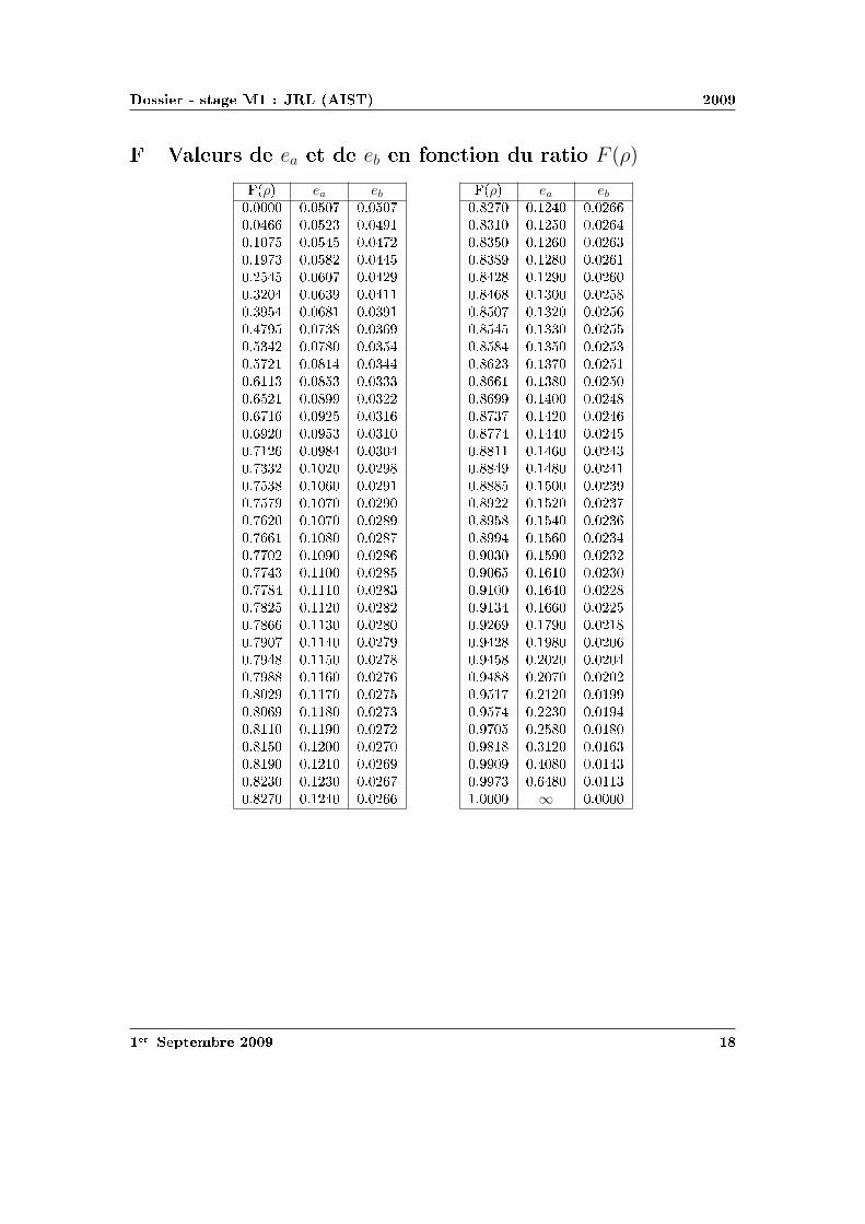


![L’Odyssée des Graphes de Diagrammes de Séquences (MSC …perso.crans.org/~genest/These.pdf · 2005. 1. 10. · lecteur à [Pap94, GJ78]. Les traces de Mazurkiewicz Comme nous](https://static.fdocuments.fr/doc/165x107/60bdd5953200e2058b00f899/laodysse-des-graphes-de-diagrammes-de-squences-msc-persocransorggenestthesepdf.jpg)