Automazioni per barriere stradali veloci Automation ... · - 3 - Modèles: G4000 Barrière avec...
20
- 1 - Documentazione Tecnica 25 rev. 5.4 11/2000 © CAME CANCELLI AUTOMATICI 119G25 G4000 / G4001 CANCELLI AUTOMATICI 1. Gruppo GARD 2. Quadro comando Accessori 3. Asta in alluminio 4. Strisce rosse fosforescenti 5. Antenna 6. Gomma protettiva 7. Lampade di segnala- zione 8. Lampeggiatore di movimento 9. Selettore a chiave 10. Batteria di emergenza 11. Colonnina per fotocellule 12. Fotocellule di sicurez- za 13. Colonnina per lettore magnetico 14. Lettore magnetico 15. Appoggio fisso 16. Sensore magnetico 1. GARD unit 2. Control panel Accessories 3. Aluminum barrier 4. Red phosphorescent strips 5. Antenna 6. Anti-collision rubber 7. Movement indicator lights 8. Flashing movement warrning light 9. Key-operated selector switch 10. Emergency battery 11. Photocell Column 12. Safety photocells 13. Column for magnetic card reader 14. Magnetic card reader 15. Fixed barrier support 16. Magnetic sensor 1. Groupe GARD 2. Armoire de commande Accessoires 3. Lisse en aluminium 4. Bandes rouges phosphorescentes 5. Antenne 6. Boudin caoutchouc anti-choc 7. Lampe de mouvement 8. Clignotant de mouvement 9. Sélecteur à clé 10. Batterie d'urgence 11. Colonnette pour photocellule 12. Photocellule de sècuritè 13. Colonnette pour lecteur de carta magnétique 14. Lecteur de carte magnétique 15. Appui fixe 16. Capteur magnétique 1. GARD- Bausatz 2. Steuerung Zubehör 3. Aluminium-Stange 4. Rote Phosphoreszenz- Streifen 5. Antenne 6. Gummi Stoßschutz 7. Bewegungs- Meldeleuchte 8. Blinkleuchte 9. Schlüsselschalter 10. Notbatterie 11. Photozellen-Säule 12. Sicherheits-Photozelle 13. Magnetkartenleser- Säule 14. Magnetkartenleser 15. Feste Stütze 16. Magnetischer Sensor 1. Grupo GARD 2. Cuadro de mando Accesorios 3. Barra de aluminio 4. Bandas roias fosforescentes 5. Antena 6. Protector de goma 7. Làmpara de movimiento 8. Làmpara intermitente de movimiento 9. Selector con Ilave 10. Baterìa de urgencia 11. Columna para fotocélula 12. Fotocélula de seguridad 13. Columna para lector magnético 14. Lector magnético 15. Apoyo fijo 16. Sensor magnético Automazioni per barriere stradali veloci Automation systems for swift road barriers Automatisations pour barrières routieres rapides Antriebe für Schnell-Schranken Automatización para barreras viales rápidas Impianto tipo - Standard installation - Installation type - Standard Montage - Instalaciòn tipo
Transcript of Automazioni per barriere stradali veloci Automation ... · - 3 - Modèles: G4000 Barrière avec...

- 1 -
DocumentazioneTecnica
25rev. 5.411/2000© CAME
CANCELLIAUTOMATICI
119G25G4000 / G4001CANCELLI AUTOMATICI
1. Gruppo GARD2. Quadro comando
Accessori3. Asta in alluminio4. Strisce rosse
fosforescenti5. Antenna6. Gomma protettiva7. Lampade di segnala-
zione8. Lampeggiatore di
movimento9. Selettore a chiave10. Batteria di emergenza11. Colonnina per
fotocellule12. Fotocellule di sicurez-
za13. Colonnina per lettore
magnetico14. Lettore magnetico15. Appoggio fisso16. Sensore magnetico
1. GARD unit2. Control panel
Accessories3. Aluminum barrier4. Red phosphorescent
strips5. Antenna6. Anti-collision rubber7. Movement indicator
lights8. Flashing movement
warrning light9. Key-operated selector
switch10. Emergency battery11. Photocell Column12. Safety photocells13. Column for magnetic
cardreader
14. Magnetic card reader15. Fixed barrier support16. Magnetic sensor
1. Groupe GARD2. Armoire de commande
Accessoires3. Lisse en aluminium4. Bandes rouges
phosphorescentes5. Antenne6. Boudin caoutchouc
anti-choc7. Lampe de mouvement8. Clignotant de
mouvement9. Sélecteur à clé10. Batterie d'urgence11. Colonnette pour
photocellule12. Photocellule de
sècuritè13. Colonnette pour
lecteur de cartamagnétique
14. Lecteur de cartemagnétique
15. Appui fixe16. Capteur magnétique
1. GARD- Bausatz2. Steuerung Zubehör3. Aluminium-Stange4. Rote Phosphoreszenz-
Streifen5. Antenne6. Gummi Stoßschutz7. Bewegungs-
Meldeleuchte8. Blinkleuchte9. Schlüsselschalter10. Notbatterie11. Photozellen-Säule12. Sicherheits-Photozelle13. Magnetkartenleser-
Säule14. Magnetkartenleser15. Feste Stütze16. Magnetischer Sensor
1. Grupo GARD2. Cuadro de mando Accesorios3. Barra de aluminio4. Bandas roias
fosforescentes5. Antena6. Protector de goma7. Làmpara de
movimiento8. Làmpara intermitente
de movimiento9. Selector con Ilave10. Baterìa de urgencia11. Columna para
fotocélula12. Fotocélula de
seguridad13. Columna para lector
magnético14. Lector magnético15. Apoyo fijo16. Sensor magnético
Automazioni per barriere stradali velociAutomation systems for swift road barriers
Automatisations pour barrières routieres rapidesAntriebe für Schnell-Schranken
Automatización para barreras viales rápidas
Impianto tipo - Standard installation - Installation type - Standard Montage - Instalaciòn tipo

- 2 -
Modelli:
G4000
Barriera con motoriduttore irreversibile ali-mentato a 24V d.c., armadio in acciaio zin-cato e verniciato, quadro di controllo ecomando interno.
G4001
Versione con armadio in acciaio inox.
Descrizione:- Barriera motorizzata adatta alla selezio-ne di ingressi con passaggio utile fino a 4m. (con accessori fino a 3.5 m., vedi pag.7).
- Progettato e costruito interamente dallaCAME S.p.A., risponde alle vigenti normedi sicurezza UNI 8612, con grado di pro-tezione IP 54.
- Garantito 12 mesi salvo manomissioni.
Accessori di completamento:
G0401
Asta in alluminio verniciato bianco se-zione 60/40/4200 mm.
In alternativa(per zone soggette a forte vento):
G0402 + G0405
Asta in alluminio tubolare verniciatobianco sezione ø 60/4200 mm. + attaccospeciale per asta.
Attenzione! Controllate che le apparecchiature di comando, di sicurezza e gli accessori siano originali CAME; ciò garantisce e rendel'impianto di facile esecuzione e manutenzione.
G0403Gomma protettiva antiurto rossa completa di tappi per astaG0401.
G0460Confezione di lampade di segnalazione a 24V con supportiper aste G0401 e scheda di intermittenza.
G0461Confezione striscie rosso fosforescente per aste.
G0462Appoggio fisso per aste.
G0463Appoggio mobile per aste.
G0465Rastrelliera in alluminio verniciata per aste.
G0467Snodo per G0401.
G0468Supporto per l'applicazione della fotocellula su armadio.
G0469Supporto per l'applicazione del lampeggiatore suarmadio.
AC
CE
SS
OR
I OP
ZIO
NA
LI
AC
CE
SS
OR
I OP
ZIO
NA
LI
AC
CE
SS
OR
I OP
ZIO
NA
LI
AC
CE
SS
OR
I OP
ZIO
NA
LI
AC
CE
SS
OR
I OP
ZIO
NA
LI
Models:
G4000
Barrier with non-reversible, 24 V d.c. gearmotor, case in galvanised steel withenamel finish, control panel and internaldrive system.
G4001
Version with stainless steel case.
Description:- This unit can be used to controlentrances up to 4 meters wide (withaccessories up to 3,5 metres, see tableon page 7).
- Designed and constructed entirely byCAME in compliance with current safetystandards (UNI 8612), and with an IP 54protecting rating.
- Guaranteed for 12 months, unlesstampered with by unauthorizedpersonnel.
Optional accessories:
G0401
Cross-section 60/40/4200 mm. aluminiumbarrier with white enamel finish.
Alternative system (for areas subject tstrong winds)
G0402 + G0405
Cross-section ø 60/4200 mm tubolaraluminium barrier with white enamelfinish + special attachment for barrier rod.
Attention! to insure easy installation and conformance with current safety norms, we raccomend installation of CAME safety and controlaccessories.
G0403Red anti-collision bumper, complete with endcaps, forG0401 barrier.
G0460Package of 6 24V signal lamps complete of supports forG0401 barriers, with flash-control circuit board.
G0461Red phosphorescent strip for barriers.
G0462Non-moving support for barriers.
G0463Moving support for barriers.
G0465White enameled aluminum fencing for barriers.
G0467Joint for G0401 barrier.
G0468Support for attachment of photocell to casings.
G0469Support for attachment of flashing beacon to casings.
OP
TIO
NA
L A
CC
ES
SO
RIE
S
GENERAL SPECIFICATIONSGENERAL SPECIFICATIONSGENERAL SPECIFICATIONSGENERAL SPECIFICATIONSGENERAL SPECIFICATIONS������
�
CARATTERISTICHE GENERALICARATTERISTICHE GENERALICARATTERISTICHE GENERALICARATTERISTICHE GENERALICARATTERISTICHE GENERALI�����

- 3 -
Modèles:
G4000
Barrière avec motoréducteur irréversiblealimenté en 24 V d.c., armoire en aciergalvanisé et verni, tableau de contrôleou commande interne.
G4001
Version avec armoire en acier inox.
Description:- Le groupe est indiqué pour le contrôledes entrées avec passages jusqu à 4 m(avec accessoires jusqu’à 3,5 m., voirtableau p. 7).
- Il a été entièrement concu et construitpar la Société CAME, conformément auxnormes de sécurité en vigueur (NFP 25-362) avec degré de protection IP 54.
- Il est garanti 12 mois sauf en casd'altérations.
Accessoires complémentaires:
G0401
Lisse en aluminium verni blanc section60/40/4200 mm.
En alternative(pour les zones sujettes à des ventsforts).
G0402 + G0405
Lisse en aluminium tubulaire verni blancsection ø 60/4200 mm. + fixation spécialepour lisse.
Attention ! Vérifiez que l’appareillage de commande, de sécurité et les accessoires sont des produits originaux CAME afin de garantirl’installation et d’en faciliter le montage et l’entretien.
G0403Coutchouc de protection antichoc rouge comprenantbouchons pour lisse G0401.
G0460Ensemble de 6 lampes de signalisation de 24V avecsupports pour lisses G0401 et carte de intermittencie.
G0461Bande rouge phosphorescente pour lisses.
G0462Appui fixe pour lisses.
G0463 Appui mobile pour lisses.
G0465Tablier en aluminium verni pour lisses.
G0467Articulation pour G0401.
G0468Support pour l 'application d'une photocellule surl'armoire.
G0469Support pour l'application du clignotant sur l'armoire.
AC
CE
SS
OIR
ES
EN
OP
TIO
NA
CC
ES
SO
IRE
S E
N O
PT
ION
AC
CE
SS
OIR
ES
EN
OP
TIO
NA
CC
ES
SO
IRE
S E
N O
PT
ION
AC
CE
SS
OIR
ES
EN
OP
TIO
N
Modelle:
G4000
Schranke mit selbsthemmendem 24 V-Gleichstrom-Getriebemotor, Gehäuse
ausverzinktem und lackiertem Stahl,eingebaute Motorsteuerung.
G4001
Ausführung mit Edelstahl-Gehäuse.
Beschreibung:-Die gruppe ist zum Antrieb vonSchranken mit Durchfahrtsbreiten bis 4m. geeignet (mit Zubehör bis 3,5 m, sieheTabelle auf Seite 7).
- Vollkommen von der CAME S.p.A. dengeltenden Sicherheitsnormen (UNI8612) entsprechend entwickelt undhergestellt. Schutzklasse IP 54.
- Garantie: 12 Monate, vorbehaltlichunsachgemäßer Handhabung undMontage.
Zubehör:
G0401
Aluminiumsstange, weiß acktiert, Schnitt60/40/4200 mm.
als Alternative (für Gebiete mit starkem Wind):
G0402 + G0405
Aluminiumrohr-Stange, weiß acktiertSchnitt ø 60/4200 mm + speziellerSchrankenbaumträger.
Achtung! Wir empfehlen original CAME-Schalt- und -Sicherheitsvorrichtungen mit entsprechendem Zubehör zu montieren, um dieeinwandfreie Montage und die problemlose Wartung der Anlage zu gewährleisten.
G0403Roter Gummi-Stoßschutz mit Stöpsel für Stange G0401
G04606-Stück-Packung 24V - Warnlampen mit Sockel fürSchranken G0401 und Blinksystemplatine.
G0461Roter Phosphoreszenz-Streifen für Stange.
G0462Feste Stütze.
G0463Bewegliche Stütze.
G0465Aluminium-Schrankengitter, weiß acktiert.
G0467Gelenkstück für G0401.
G0468Photozellenmontagehalter für Schranken.
G0469Blinkleuchtenmontagehalter für Schranken.
ZU
BE
HÖ
R A
UF
AN
FR
AG
E
CARACTÉRISTIQUES GÉNÉRALÉSCARACTÉRISTIQUES GÉNÉRALÉSCARACTÉRISTIQUES GÉNÉRALÉSCARACTÉRISTIQUES GÉNÉRALÉSCARACTÉRISTIQUES GÉNÉRALÉS���
��
ALLGEMEINE MERKMALEALLGEMEINE MERKMALEALLGEMEINE MERKMALEALLGEMEINE MERKMALEALLGEMEINE MERKMALE������
�

- 4 -
Modelos:
G4000
Barrera con motorreductor irreversiblealimentado a 24V d.c., armario de acerogalvanizado y barnizado, cuadro decontrol y mando interno.
G4001
Versión con armario de acero inox.
Descripción:- El grupo es adecuado para la selecciónde entradas con pasos de hasta 6,5 m(con accesorios hasta 6 m, ver tabla apág 7).
- Diseñado y fabricado enteramente porCAME S.p.A., cumple con las normas deseguridad vigentes UNI 8612, con gradode protección IP54.
- Garantizado 12 meses, salvomanipulaciones.
Accesorios que lo completan:
G0401
Barra de aluminio barnizado blancosección 60/40/4200 mm.
Como alternativa(para zonas sometidas a viento fuerte):
G0402 + G0405
Barra de tubo de aluminio barnizadoblanco sección ø 60x4200 mm. + uniónespecial para asta.
Atención! Comprobar que los equipos de mando, de seguridad y los acesorios sean originales CAME; lo cual garantiza y facilita eluso y el mantenimiento del aparato.
G0403Goma protectora a prueba de golpes de color rojo, dotadade tapones para barra G0401.
G0460Envase de 6 lámparas de señalización de 24 V dotadas desoportes para barras G0401 y tarjeta de intemitencia.
G0461Banda roja fosforescente para las barras.
G0462Apoyo fijo para las barras.
G0463Apoyo móvil para las barras.
G0465Estante de aluminio barnizado blanco para las barras.
G0467Articulación para G0401.
G0468Soporte para la aplicación de la fotocélula en losarmarios.
G0469Soporte para la aplicación de la lámpara intermitente enlos armarios.
AC
CE
SO
RIO
S O
PC
ION
AL
ES
:A
CC
ES
OR
IOS
OP
CIO
NA
LE
S:
AC
CE
SO
RIO
S O
PC
ION
AL
ES
:A
CC
ES
OR
IOS
OP
CIO
NA
LE
S:
AC
CE
SO
RIO
S O
PC
ION
AL
ES
:
Caratteristiche tecniche - Technical features - Caractéristiques technique - Technische Daten - Descripción técnica
Misure di ingombro - External dimensions - Mesures d'encombrement - Außenabmessungen - Dimensiones máximas
������
���
���
� �
����
��
CARACTERÍSTICAS GENERALESCARACTERÍSTICAS GENERALESCARACTERÍSTICAS GENERALESCARACTERÍSTICAS GENERALESCARACTERÍSTICAS GENERALES����
�
(1) Servizio intensivo - Heavy-duty - Utilisation intensive - Starkbetrieb - Servicio intensivo
�� ����
������
��
��� ������
� ����������
���
��������� ������� ����
�������� �������� ��
�����������
��� ������ � �������
��� ��� ����� ������
��� �������
� ������ ��������
����������� ����������� �����
� ������� �
����������� � � ��������
������������������������ �
������������
���� � ������� ��������
���� ��� ����� ���������
������������������
� ����������� �
� ������������
�������!� �"
��� ����������������������
������ ������ �����
���� ������� ����
G4000G4001
47 Kg 230V a.c. 24V d.c.1,3A max.
(230V)15A max.
(24V)300 W ... (1) 1/202 200 Nm 2 ÷ 6 s

- 5 -
A - Armadio in lamiera di ac-ciaio da 2,5 mm con finiture dizincatura e verniciatura(G4000), o in acciaio inox sati-nato da 2 mm (G4001), dotatodi predisposizioni per l'inseri-mento di tutti gli accessori dicompetenza.Sportello di ispezione internafissato all'armadio con unachiave personalizzata. B - Base di ancoraggio in ac-ciaio con finiture di zincaturacompleta di quattro zanche erelativi bulloni per il fissaggiodell'armadio al pavimento.
C - Flangia attacco sbarra inacciaio con finiture di zincatu-ra; permette un rapido e sicurobloccaggio della sbarra conpossibilità di adattare aste ditipo diverso.
D - Sblocco del motoriduttoreche, grazie ad un cinematismospeciale, è attuato mediantechiave personalizzata.
E - Motore in corrente conti-nua a 24 V.Riduttore irreversibile con cas-sa in pressofusione di allumi-
nio; all'interno opera un siste-ma di riduzione a vite senzafine con lubrificazione a gras-so fluido permanente.- Tutti gli organi di rotazionesono su cuscinetti a lubrifica-zione permanente o snodi sfe-rici autolubrificanti. F - N. 1 molla di contrappeso ebilanciatura del movimento. G - Fermi meccanici di sicu-rezza interni. H - Gruppo finecorsa. I - Quadro comando ZL37.
A - Case constructed in 2.5 mmgalvanized stainless sheet with anenamel finish (G4000), or in 2 mm.stainless steel, with a satin finish(G4001), factory-configured toaccept all required accessories.The access door for inspectioncan be locked onto the case witha personal key. B – Mounting base in galvanizedsteel, complete with four anchorstays and bolts for anchoring thecase to the pavement.
C – The flange is in galvanizedsteel. This holder allows the barrierto be quickly and securely locked.
D - The gear motor lock system,thanks to a special mechanicalsystem, can be locked with a per-sonal key.
E - Motor: 24V d.c.Reduction gear: non reversible,with die-cast aluminum housing.This unit uses an internal wormgear as the reduction system, andis permanently lubricated with liquidgrease.- The barr ier rotates onpermanently-lubricated bearingsor self-lubricating ball joints.
F - A spring acts as the counter-weight/balance system (for preci-se, uniform movement).
G - An internal shock absorber/barrier travel stop is provided.
H - Limit switch unit. I - Control panel ZL37.
A - Armoire réalisée en tôled'acier de 2,5 mm avec finitiongalvanisée at vernie (G4000); oubien en acier inox satinée de 2mm. (G4001). concue de tellefacon qu'il est possible debrancher tous les accessoiresappropriés. Porte pour lecontrôle doitêtre fixée àl'armoire au moyen d'une clépersonnalisée. B – Base d'ancrage en acieravec finition galvanisée,comprenant quatre ètriers et lesboulons correspondantspermettant la fixation del'armoire au sol. C – Bride en acier avec finitiongalvanisée. Il permet un blocagerapide et sûr de la lisse. D - Le déblocage dumotoréducteur, grace à un
cinématisme spécial, s'effectueau moyen d'une clépersonnalisée. E - Moteur en courant continu24V.Réducteur irréversible avecboîte en aluminium moulé souspression, à l'intérieur duquelopère un système de rèductionau moyen d'une vis sans finavec lubrification par graissefluide permanente. -Rotation sur des roulements àlubrification permanente ou arti-culations sphériques autolubri-fiantes. F - N. 1 ressort de compen-sation et de balance dumouvement. G - Arrêt mecanique desécurité. H - Groupe fins de course. I - Armoire de commandeZL37.
A - Schrank: Werksseitig zumEinbau des notwendigen Zubehörsausgerüstet; aus verzinktem undlackiertem Stahlblech, 2,5 mmstark (G6000) bzw. aussatiniertem Volledelstahlblech,2mm stark, (G6001). DieAbdeckplatte wird mittelsindividuellem Schlüssel amSchrank befestigt.
B – Ankerplatte aus verzinktemStahl mit vier Fundamentankernund dazugeörenden Anker-schrauben zur Bodenbefestigungdes Schrankes. C – DerFlansch aus verzinktemStahl gewährleistet sicheres undschnelles Schließen derSchranke, Montageverschiedener.
D - Entsperren: Das Entsperrendes Getriebemotors erfolgt dank
eines Sondergetriebes durchindividuellen Schlüssel.
E - Motor: 24V Gleichstrom.Untersetzungsgetriebe: Getrie-beumkehrmotor in Aluminium-druckgußgehäse, Schneckenunt-ersetzungsgetriebe und Dauer-schmierung mittels flüssigemSchmiermittel.- Rotation auf dauergeschmiertenLagern oder selbstschmierendeKugelgelenke. F - Eine Gegengewicht- undGewichtsausgleichsfeder ge-währleistet. G - Innen eingebauter StangenFeststellstoßdämpfer.
H - Endschaltergruppe.
I - Steuergerät ZL37.
A - Armario de chapa de acerode 2,5 mm con acabadocincado y barnizado (G6000), ode acero inox satinado de 2 mm(G6001), dotado depredisposiciones para laintroducción de todos losaccesorios.Portillo para inspeccion inter-na fijado por medio de una Ilavepersonalizada. B – Base de anclaje de acerocon acabado cincado dotadade cuatro grapas y de lospernos relativos para la fijacióndel armario en el suelo. C – Brida en acero con acabadocincado, consiente el ràpido yseguro bloqueo de la barra. D - Desbloqueo delmotorreductor, gracias a uncinematismo especial, realizado
mediante una Ilavepersonalizada. E - Motor en corriente conti-nua de 24 V.Reductor irreversible con cajaen aluminio fundido, en suinterior actúa un sistema dereducción por tornillo sin fincon lubricación por grasa flui-da permanente. -Rotación sobre cojinetes conlubricación permante y articula-ciones de bola autolubricantes. F - N. 1 resorte de contrapesoy equilibración del movimiento. G - Amortiguador tope barrainterno. H - Grupo final de carrera. I - Cuadro de mando ZL37.
#
$
%
�
�
�
�
�
�
Description techniqueDescription techniqueDescription techniqueDescription techniqueDescription technique�
��� ��Technical descriptionTechnical descriptionTechnical descriptionTechnical descriptionTechnical description
�
�������
Technische BeschreibungTechnische BeschreibungTechnische BeschreibungTechnische BeschreibungTechnische Beschreibung�
������� Déscripcion técnicaDéscripcion técnicaDéscripcion técnicaDéscripcion técnicaDéscripcion técnica
�
�����
Descrizione tecnicaDescrizione tecnicaDescrizione tecnicaDescrizione tecnicaDescrizione tecnica�
�����

- 6 -
Base di ancoraggio armadioMounting base for caseBase d'ancrage armoireAnkerplatte SchrankBase de anclaje armario
MONTAGGIO - MONTAGGIO - MONTAGGIO - MONTAGGIO - MONTAGGIO - INSTALLATION - MONTAGE - - MONTAGE - - MONTAGE - - MONTAGE - - MONTAGE - MONTAGE - MONTAJE- MONTAJE- MONTAJE- MONTAJE- MONTAJE
2) - Procedere allaposa del gruppo: è consi-gliabile sistemare l'armadiocon lo sportello ispezio-nabile vista interna (vedipag. 8).Montare l'asta calcolando lagiusta lunghezza e fissarlacon l'attacco porta-asta Atramite le quattro viti in do-tazione.Registrare la linearità oriz-zontale e verticale dell'astaagendo sui rispettivi fermimeccanici interni B e C.
2) - Place the unit on theconcrete base: it is goodpractice to install the case sothat the access door can beopened from the interior of theinstallation site (see on page8).Mount the barrier as follows:first, determine the length ofbarrier required. Then, mountthe barrier holder with the fourscrews provided.When is the open position, thebarrier can be straightened byadjusting the internal shockabsorber/travel stop (B - C).
2) - Procéder ensuite à la pose dugroupe: il est conseillé de placerl'armoire avec la porte de contrôle vueintérieure (voir p. 8).Monter la lisse en calculant la longueurexacte, puis fixer le support de la barrecorrespondante en utilisant les quatrevis fournies avec l'appareillage.On obtient la linéarité de la lisse enposition d'ouverture en réglantl'amortisseur de l'arrêt interne B et Cde la lisse.
2) - Gruppe aufstellen: Der Schranksollte mit Abdeckplatte zur Innenseiteaufgestellt werden (siehe Seite 8).Nach Berechnung der Stangenlänge,Stange montieren und Stangenhaltermittels der vier mitgelieferten Schraubenfestschrauben.Die Geradheit der Stange bei geöffneterSchranke wird mittels Einstellung desinneren Stangenfeststell-Stoßämpferserzielt (B - C).
2) - Colocar el grupo: se reco-mienda colocar el armario con elportillo inspeccionable visto desde elinterior (ver pág. 8).Montar la barra calculando la longitudcorrecta y fijar el porta-barra relativomediante los cuatro tornillos delequipo.La alineación de la bara abierta seobtiene ajustando el amortiguador tope-barra interno (B y C).
���
� � �
1) - Predisponer, en función de lasmedidas del grupo, una plataforma decemento introduciendo las grapas deanclaje y la base relativa que consien-ten fijar el grupo.La base de fijación debe estar totalmen-te horizontal, con los extremos limpiosy la rosca de los tornillos en superficie.De la misma deben sobresalir loscables para las conexiones eléctricas.
1) - Pour a concrete base of thecorrect size for installation of the unit.When pouring, sink the anchoring staysand the mounting base for the unit intothe concrete.The concrete base must be perfectly leveland clean from end to end. All screwthreads must be completely accessiblefrom the surface of the concrete base.The electrical cables for the unit must alsoprotrude from the base.
1) - En tenant compte des dimen-sions du groupe, préparer une plate-forme en ciment dans laquelle serontnoyés les étriers d'ancrage e la basecorrespondante qui permettront defixer le groupe.La base de fixation devra être parfaite-ment de niveau et propre sur toute sasurface.Le cables pour le branchementélectrique devront sortir de cette base.
1) - Ein den Abmessungen derGruppe entsprechendes Fundament zumEinbetonieren der an der Ankerplatteangebrachten Fundamentanker, die derBefestigung der Gruppe dienen,vorbereiten.Die Befestigungsplatte muß eben,sauber und livell iert sein und dieAnkerschraubengewinde müssenvolkommen frei über derFundamentebene liegen.Die Stromversorgungskabel müssen ausdem Fundament herausragen.
1) - Predisporre, dimensionandolain base alle misure del gruppo, una piaz-zola di cemento con annegate le zanchedi ancoraggio e la relativa base che per-metteranno il fissaggio del gruppo.La base di fissaggio dovrà risultare per-fettamente in bolla, pulita in tutta la suaestremità con il filetto delle viti com-pletamente in superficie.Dalla stessa dovranno emergere i caviper il collegamento elettrico.
� ��
���
200
145
220
265
Uscita caviCable exitSortie des càblesKabelausgangSalida cables
A
CB

- 7 -
bilanciamento asta - gate rod balancing - equilibrage barre - stangeausgleich - equilibracion barra
La barriera G4000 viene fornita di serie con la mollamontata sulla posizione B.Se la configurazione finale della vostra barriera lo richie-de (vedi illustrazioni), sbloccare il motoriduttore e cam-biare posizione alla molla.Per un eventuale bilanciamento fine, vedere la pagina se-guente.
Barrier G4000 is supplied with spring installed atposition B.If the final configuration of your barrier requires a change inthe position of the spring (see illustrations),unlock the gear motor and change the position of the spring.If precise balancing of the barrier rod is required, see thenext page.
La barrière G4000 est fournie de série avec leressort monté sur la position B.Si cela est nécessaire pour la configuration finale de labarrière (voir illustrations), débloquer le motoréducteuret changer la position du ressort.Pour un éventuel équilibrage fin, voir la page suivante.
Das Schrankenmodell G4000 wird serienmäßig mit inPosition B montierter Feder geliefert.Wenn es die endgültige Schrankenkonfiguration erfordernsollte (siehe Abbildungen), den Getriebemotor entblocken
unddie Federposition ändern.Bei eventuell erforderlichem Feinausbalancieren, siehenächste Seite.
La barrera G4000 se suministra de serie con elresorte montado en la posición B.Si la configuración final de su barrera lo requiere (verfigura), desbloquear el motorreductor y cambiar laposición del resorte.Para un eventual equilibrado fino, ver la página siguiente.
L
Posizione mollaSpring position
Position ressortFedereinstellung
Posiciòn resorte
L m <2.5 <3.5 <4
A A B
L
Posizione mollaSpring position
Position ressortFedereinstellung
Posiciòn resorte
L m <2.5 <3.5
A B
L
Posizione mollaSpring position
Position ressortFedereinstellung
Posiciòn resorte
L m <2.5
B
con rastrrelliera o appoggio mob
with rack or mobile supportavec tablier ou appui mobile
mit Schrankengitter oder feste Stützcon estante o apoyo mòvil
B
A
fissaggio mollaattach springfixation ressortFedernhalterungenganche resorte
��
�
�
�
�

- 8 -
bilanciamento asta - gate rod balancing - equilibrage barre - stangeausgleich - equilibracion barra
Per bilanciare con precisionel'asta:
1) - sbloccare il motoriduttore (pag. 5,part. D);2) sbloccare il dado di serraggio B deltirante A;3) - agire manualmente sulla molla peraumentare/diminuire la trazione dellastessa fino a che l'asta si stabilizza inposizione di 45°;4) - serrare quindi il dado di bloccaggioe bloccare il motoriduttore.
&'()*+�(,�-../&-�����01����������� !��"#$&'()*�2�-+&33+*�����01%��&'() �"*&+�������&'()*+�(�-4(3�����&5,-
�(,-��������&* .'-6�����* �"����6+'.(����
&'()*+�����,1�.-)�0)-,-��&�!#&�"#$�����$��,! '�-#!& �&'()*�����,1�2�('*&.63(*&-)�����������������������$�&'()*+�����,1�(,�('*&.63(.&7)
���8
(1�
����8(1�
�
�
�
'(5&-)+�*))!&+�.#"/�'(.*&-)�*+0"(. '(..&9)
�
To balance the barrier rod precisely,proceed as follows:1) Unlock the gear motor (p. 5, ref. D);2) Loosen locknut B on tension rod A;3) Manually adjust the spring to increase/decrease its tension until the barrier rodstabilises at a 45° angle;4) Now, tighten the locknut and lock thegear motor.
Para equilibrar con exactitud elasta:1) - desbloquear el motorreductor (pág.5, det.D);2) - desbloquear la tuerca de cierre Ddel tirante A;3) - actuar manualmente en el resortepara aumentar/disminuir la tracción delmismo hasta que el asta se estabilizaen la posición de 45º;4) - enroscar la tuerca de fijación ybloquear el motorreductor.
Zum präzisen Ausbalancieren desSchrankenbaums:1) - den Getriebemotor entblocken (Seite5, Detail D);2) - Die Befestigungsmutter B desZugstabs A lockern;3) - mit der Hand die Federspannung biszur endgültigen Stabilisierung desSchrankenbaums in 45°-Stellung
erhöhenbzw. verringern.4) - die Befestigungsmutter wiederfestziehen und den Getriebemotorblockieren.
Pour équilibrer avec précision lalisse:1) - débloquer le motoréducteur (p. 5,dét. D);
2) débloquer l’écrou de serrage B dutirant A;
3) - Agir manuellement sur le ressortpour en augmenter/diminuer la tractionjusqu’à ce que la lisse se stabilise enposition
de 45°;4) - serrer ensuite l’écrou de blocage etbloquer le motoréducteur.
barriera dx / sx - rod barrier dx / sx - barrière dx /sx - Schranke dx /sx - barrera dx /sx
Le barriereG4000 sono forni-
te DX o SX a richiesta.Se in seguito si vuoleinvertire la rotazione,richiedere la relativadocumentazione.
G4000 barriersare
furnished in right-hand or left-handversions upon request. Ifthe direction of rotationmust be changed at alater time, contact CAMEfor the relativeinstructions.
Les barrièresG4000 sont
fournies sur demandecôté droit ou gauche. Si l’on désire par lasuite invertir la rotation,demander lad o c u m e n t a t i o ncorrespondante.
Die Schranken-mo-delle G4000
werden, auf Anfrage, alsRechts-bzw.Linksausführung gelie-fert. Wenn zu einemspäteren Zeitpunkt eineDrehrichtungsumkehrungerforderlich werdensollte, dann fordern siebitte die entsprechendenUnterlagen an.
Las barrerasG4000 se
suministran dcha. oizda. a encargo. En elcaso de que se quisieraposteriormente invertirla rotación, solocitar lad o c u m e n t a c i ó ncorrespondiente.
��� � � �
�
��
���
barriera sinistraLeft-hand barrier
Barrière gaucheLiksschranke
Barrera izquierda
LATO INGRESSOENTRANCE SIDECÔTÉ ENTRÉE
ZUFAHRTS-BZW. ZUGANGSSEITELADO ENTRADA
ZONA INTERNA - INSIDE AREA- ZONE INTERNE - INNENBEREICH - ZONA INTERNA
barriera destraRight-hand barrierBarrière droiteRechtsschrankeBarrera derecha
LATO INGRESSOENTRANCE SIDECÔTÉ ENTRÉE
ZUFAHRTS-BZW. ZUGANGSSEITELADO ENTRADA
ZONA INTERNA - INSIDE AREA- ZONE INTERNE - INNENBEREICH - ZONA INTERNA

- 9 -
DESCRIPTION TECHNIQUE CARTE BASE ZL37
DESCRIZIONE TECNICA SCHEDA BASE ZL37
TECHNICAL DESCRIPTION ZL37 MOTHERBOARD
La scheda comando va alimentata a (230Va.c.) sui morsetti L1 e L2 ed è protetta iningresso con fusibile da 3.15A.I dispositivi di comandi sono a bassatensione (24V), protetti con fusibile da 2A.La potenza complessiva degli accessori a24V, non deve superare i 40W.
SicurezzaLe fotocellule possono essere collegate
e predisposte per:a) Riapertura in fase di chiusura;b) Stop totale: arresto della sbarra conconseguente esclusione dell'eventualeciclo di chiusura automatica, per ripren-dere il movimento agire sulla pulsantierao sul trasmettitore radio;c)Chiusura immediata: l'asta si abbassaautomaticamente dopo che il veicolo haoltrepassato il raggio d'azione deidispositivi di sicurezza, collegato suimorsetti 2-C5;- Dispositivo amperometrico: vedi NOTA;- Tempo di lavoro fisso 20 secondi.
Accessori collegabili
- Scheda LB35 che permette l'alimentazio-ne dell'automazione tramite batterie nelcaso di mancanza di energia elettrica. Alripristino della tensione di linea esegueanche la loro ricarica (vedi relativo foglioistruzioni);- Lampeggiatore di movimento;- Ricevitore radio ad innesto.
Altre funzioni selezionabili- Chiusura automatica. Il temporizzatore dichiusura automatica si autoalimenta afinecorsa di apertura. Il tempo regolabile, écomunque subordinato dall'intervento dieventuali accessori di sicurezza e si esclu-de dopo un intervento di «stop» totale o inmancanza di energia elettrica;- Rilevazione ostacolo. A motore fermo(sbarra chiusa, aperta o dopo un comandodi stop totale), impedisce qualsiasi movi-mento se i dispositivi di sicurezza (es.fotocellule) rilevano un ostacolo;- Funzionamento a «uomo presente»;- Prelampeggio in apertura e chiusura;- Attivazione di una uscita a 24V durante lefasi di movimento e in posizione di chiusu-
ra,- Funzionamento slave, nel caso di duemotori abbinati (vedi pag.8);- Funzione di aumento dell'azione fre-nante della sbarra;- Tipo di comando:
- apre-chiude-inversione;- solo apertura.
Regolazioni- Trimmer TCA = Tempo chiusura auto-matica: da 0 a 120";- Trimmer SENS. = Sensibilitàamperometrica: min/max.
Attenzione: prima di intervenire all'inter-no dell'apparecchiatura, togliere latensione di linea e scollegare le batterie(se inserite).
ITALIANO
This control board is powered by 230V a.c.across terminals L1 and L2, and is protectedby a 3.15A fuse on the main power line.Control systems are (24) powered by lowvoltage and protected with by a 2A fuse.The total power consumption of 24Vaccessories must not exceed 40 W.
SafetyPhotocells can be connected to obtain:
a)Re-opening during the closing cycle;b)Total stop: the movement of the bar isinterrupted, and the automatic closure cycleis disactivated. Use the keyboard or the ra-dio transmitter to resume movement of thebar;c)Immediate closure (the bar is loweredautomatically after the vehicle has passedthe safety devices, on the terminals 2-C5 ofthe control panel;- Amperometric safety device: see NOTE;- Fixed operating time of 20 sec.
Accessories which can be connectedto this unit
- LB35 board, used to power the automation
system using battery power in case of a powerfailure. When the power supply is restored,the batteries are recharged automatically(refer to instruction sheet);- Flashing signal light when bar is in motion;- Plug-in radio receiver.
Other functions available- Automatic closing: The automatic closingtimer is automatically activated at the end ofthe opening cycle. The preset, adjustableautomatic closing time is automaticallyinterrupted by the activation of any safetysystem, and is deactivated after a total stopcommand or in case of power failure;- Obstacle detection: When the motor isstopped (bar is closed, open or half-open afteran emergency stop command), the transmitterand the control pushbutton will be deactivatedif an obstacle is detected by one of the safetydevices (for example, the photocells);- “Human presence” operation;- Flashing light activated before opening andclosing cycle begins;- Activation of a 24V output signal during themovement phases and in the closed position;
- "Slave" operation when two motors are usedin combination (see page 8);- Function that increases the braking actionon the barrier;- Selection of command sequence:
-open-close-reverse;-open only.
Adjustments- Trimmer TCA = Automatic closing time: 0"to 120";- Trimmer SENS = Sensitivity ofamperometric safety system: min/max.
Important: Shut off the mains power anddisconnect the batteries before servicing theinside of the unit.
FRANÇAISFRANÇAISFRANÇAISFRANÇAISFRANÇAIS
La carte de commande doit êtrealimentée avec une tension de 230Vsur les bornes L1 et L2 et elle estprotégée en entrée par un fusible deligne de 3.15A.Les dispositifs de commande sont àbasse tension (24V) et protégés avecfusible de 2A. La puissance totale desaccessoires à 24V, ne doit pasdépasser 40W.
SécuritéIl est possible de brancher des
photocellules et de les programmerpour:a)Réouverture en phase defermeture;b)Stop total: arrêt de la barre avecconséquente exclusion de l'éventuelcycle de fermeture automatique; pourreprendre le mouvement, agir sur lesboutons-poussoirs ou sur l'émetteurradio;c)Fonction de fermeture immédiate:la barrière s'abaisse automa-tiquement dès que le vèhicule adépassé le rayon d'action desdispositifs de sécuritè (ex:photocellules) sur les bornes 2-C5 du
armoire de commande;- Dispositif ampèremétrique: voirNOTE;- Temps de fonctionnement fixe de 20secondes.
Accessoires branchés- Carte LB35 permettant l'alimentationde l'automatisme avec batteries en casde coupure de courant. Une fois latension de réseau rétablie, elle procèdeégalement à la recharge des batteries(voir feuille d'instructionscorrespondante);- Clignotant de mouvement;- Récepteur radio à insertion.
Autres fonctions pouvant êtresélectionnées
- Fermeture automatique. Le tempo-risateur de fermeture automatique estautoalimenté à la fin du temps de lacourse en ouverture. Le tempsréglable est programmé, cependant, ilest subordonné à l’interventiond’éventuels accessoires de sécurité etil est exclu après une intervention de“stop” total ou en cas de coupure decourant;
- Détection obstacle. Quand le moteurest arrêté (lisse fermé, ouvert ousemi-ouvert, cette position estobtenue avec une commande de stoptotal), annule toute fonction del’émetteur ou du bouton-poussoir encas d’obstacle détecté par lesdispositifs de sécurité (ex.Photocellules) ;- Fonctionnement “homme mort”.- Préclignotement en ouverture et enfermeture;- Activation d’une sortie à 24V pendantles phases de mouvement et enposition de fermeture;-Fonctionnement "slave" en cas dedeux moteurs associés (voir page 8);- Fonction augmentation de l'action defreinage de la barrière;- Types de commande :
-ouverte - fermée - inversion;-seulement ouverture.
Réglages- Trimmer T.C.A. = Temps de fermetureautomatique : de 0" à 120";- Trimmer SENS = Sensibilitéampèremetriqué min/max.
ENGLISHENGLISHENGLISHENGLISHENGLISH

- 10 -
TECHNISCHE BESCHREIBUNG GRUNDPLATINE ZL37
DESCRIPCIÓN TÉCNICA TARJETA BASE ZL37
Die Grundplatine wird mit einer Spannungvon 230V über die Klemmen L1 und L2gespeist und ist am Eingang mit einer 3.15-A-Hauptsicherung geschützt. DieSteuerungen erfolgen mit Niederspannungund sind durch enie 2-A-Sicherunggeschützt. Die Gesamtleistung des 24-V-Zubehörs darf 40W nicht überschreiten.
SicherheitsvorrichtungenDie Lichtschranken können für folgende
Funktionen angeschlossen bzw. vorbereitetwerden:a)Wiederöffnen beim Schließen;b)Totalstop: Stillstand des Schrankenbaumsunter Ausschluß der eventuelldarauffolgenden automatischenSchließfunktion. Die Wiederaufnahme desNormalbetriebs erfolgt durch Tasten- oderFunksendersteuerung;c)Sofortige Schließfunktion: Die Schrankesenkt sich automatisch nachdem das Fahr-zeug den Aktionsradius der Sicherheits-vorrichtung (z.B: Lichtschranke) überfahrenhat. Anschluß auf den Klemmen 2-C5 desSteuergeräts;- Amperemetr ische Vorrichtung: sieheHINWEIS;
- festgelegte Laufzeit von 20 Sek..
Anschließbares Zubehör - Platine LB35: ermöglicht bei Netzspan-nungsausfall die Stromversorgung desAntriebssystems mittels Notbatterien. Beineuerlicher Netzspannungsversorgungerfolgt das automatische Wiederaufladen derBatterien. (Siehe entsprechende Bedi-enungsanleitung);- Blinkleuchte "Tor in Bewegung";- Steck-Funkempfänger.
Andere Wahlfunktionen- Schließautomatik. Der Schließautomatik-Zeischalter speist sich beim Öffnen am Endeder Torlaufzeit selbst. Die voreingestellte Zeitist auf jeden Fall immer dem Eingriff eventuellerSicherheits vorrichtungen untergeordnet undschließt sich nach einem “Totalstop"-Eingriffbzw. bei Stromausfall selbst aus;- Hinderniserfassung. Bei stillstehendemMotor (Schrankenstange geschlossen,geöffnet oder durch eine Totalstop-Steuerunghalb geöffnet) wird bei durch dieSicherheitsvorrichtungen (z.B.: Licht-schranken) erfaßtem Hindernis jede Sender-oder Drucktasterfunktion annulliert;
- Funktion “Bedienung vom Steuerpult”;- Vorblinken beim Öffnen und Schließen;- Aktivierung eines 24-V-Ausgangs währendder Bewegungsphasen und beiSchließstellung;- Slave-Betrieb, bei zwei miteinandergekoppelten Motoren (siehe Seite 8);- Zur Bremskrafterhöhung;- Steuerart:
a) Öffnen - Schließen - Torlaufumsteuerung;
b) nur Öffnen.
Einstellungen- Trimmer TCA = Zeiteinstellung Schließ-automatik: von 0 Sek. bis 120 Sek.;- Trimmer SENS = AmperemetrischeAnsprechempfindlichkeit: min/max.
Achtung: Das Gerät vor Eingriffen im innerenspannungsfrei schalten und die Stromzufuhrmittels Batterien (falls zugeschaltet)unterbrechen.
Il dispositivo ampero-metrico, in presenzadi ostacolo, provoca:a) l'arresto della sbar-ra se in fase di apertu-ra;b) l'inversione di mar-cia se in fase di chiu-sura.Attenzione nel caso b,dopo 3 rilevamentid'ostacolo consecuti-vi, la sbarra si ferma inapertura e vieneesclusa la chiusuraautomatica; per ri-prendere il movimen-to bisogna agire sullapulsantiera o sul tele-comando.
La tarjeta de mando se alimenta conuna tensión de 230V en los bornes L1 yL2 y está protegido en entrada confusible de línea de 3.15A. Losdispositivos de mando son a bajatensión (24V), protegidos por fusible a2A. La potencia total de los accesorios a24V, no debe superar los 40W.
SeguridadLas fotocélulas pueden estar
conectadas y predispuestas para:a)Reapertura en la fase de cierre;b)Parada total: parada de la barra con laconsiguiente exclusión del ciclo decierre automatico, para reactivar elmovimiento actuar en el teclado o en eltransmisor de radio;c)Cierre inmediato: la barra bajaautomáticamente después que elvehículo ha superado el radio de acciónde los dispositivos de seguridad (por ej:fotocélulas) en los bornes 2-C5 delcuadro eléctrico;- Dispositivo amperométrico: mirarNOTA;- Tiempo de trabajo fijo a 20 seg.
When an obstacle isencountered, theamperometric lockingdevice intervenes asfollows:a) if in the aperturephase, the bar stops;b) if in the closure phase,the movement of the baris reversed.N.B.: In situation (b), if anobstacle is detectedthree times, the bar stopsduring aperture, andautomatic closure isdisactivated.Use the keyboard or theradio transmitter toresume movement of thebar.
En présence d'obsta-cle, le dispositif ampè-remétrique de blocagecause:a) si en phase d'ouver-ture, l'arrêt de la barre;b) si en phase de ferme-ture, l'inversion dumouvement.Attention: dans le caseb), après 3détectionsd'obstacle consé-cutives, la barres'arrête en ouverture etla fermeture automa-tique est exclue.Pour reprendre lemouvement, il faut agirsur les boutons-pous-soirs ou sur la télécom-mande,
Bei Auftreten vonHindernissen bewirkt diea m p e r e m e t r i s c h eSicherheitsvorrichtung:a) in der Öffnungsphaseden Schrank-enstillstand;b) in der Schließen dieB e w e g u n g s u m k e h r(Sicherheitsrücklauf).Achtung: im Fall b) bleibtdie Schranke nach 3hintereinander erfolgtenHinderniserfassungenoffen und die Schließ-automatik wird ausg-eschlossen. Die Wieder-aufnahme des Normal-betriebs erfolgt mittelsTasten- bzw. Fern-steuerung.
El dispositivo ampe-rometrico de bloqueo,en presencia deobstaculo provoca:a) en fase de aperturala parada de la barra;b) en fase de cierre lainversión de lamarcha;Atención!: En el casob), despus de 3 detec-ciones de obstaculoconsecutivas, la bar-ra se para en aperturay se excluye el cierreautomatico; parareactivar elmovimiento se debeactuar en el teclado oen el mando adistancia.
DEUTSCHDEUTSCHDEUTSCHDEUTSCHDEUTSCH
ESPAÑOLESPAÑOLESPAÑOLESPAÑOLESPAÑOL
NOTA / NOTE / NOTE / HINWEIS / NOTA
Accesorios conectables- Tarjeta LB35 que permite la alimentaciónde la automatización mediante baterías encaso de falta de energía eléctrica. Una vezreactivada la tensión de línea efectatambién su recarga (vese lacorrespondiente hoja de instrucciones);- Lámpara intermitente de movimiento;- Radioreceptor a encastre.
Otras funciones seleccionables- Cierre automático. El temporizador decierre automático se autoalimenta en fin-de-tiempo carrera en fase de apertura. Eltiempo prefijado regulable, sin embargo,está subordinado a la intervención deposibles accesorios de seguridad y seexcluye después de una intervención deparada total o en caso de falta de energíaeléctrica;- Detección obstáculo. Con el motorparado (barra cerrada, abierta o enposición semi-abierta obtenida a travésde un comando de stop total), anulacualquier función del transmisor o delbotón en caso de obstáculo detectado porlos dispositivos de seguridad (porejemplo: fotocélulas);
- Funcionamiento a “hombre presente”;- Preintermitencia en fase de apertura ycierre;- Activación de una salida a 24V durantelas fases de movimiento y en posiciónde cierre;- Funcionamiento slave, en el caso dedos motores acoplados (ver pg.8);- Función de aumento de la accíon fre-nante de la barra;- Tipo de mando:
-apertura-cierre-inversión;-sólo apertura.
Regulaciones- Trimmer TCA = Tiempo cierre auto-mático: de 0" a 120”;- Trimmer SENS = Sensibilidad ampero-métrica: min/max.
Atención: antes de actuar dentro delaparato, quitar la tensión de línea ydesecnetar las baterías (si estuvieranconectadas).

- 11 -
21 3 4 5 6 7 8 9 10
��$���������:���������:�����������:�� ����������:�������������;�
22222
33333
44444
55555
66666
77777
88888
9 9 9 9 9
� �� ���������������
1 Morsettiere di collegamento 2 Fusibile di linea 3.15A 3 Fusibile accessori 2A 4 Dip-switch "selezione funzioni" 5 Innesto scheda radiofrequenza (vedi tabella) 6 Trimmer TCA: regolazione tempo di chiusura
automatica 7 Trimmer SENS: regolazione sensibilità aperometrica 8 Pulsante memorizzazione codici 9 LED di segnalazione codice radio / chiusura automa-
tica10 Connettori alimentazione motore11 Connettori per il collegamento caricabatterie (LB35)12 Jumper selezione tipo di comando per pulsante in 2-
7MAIN COMPONENTS
1 Terminal block for external connections 2 3.15A line fuse 3 2A accessories fuse 4 "Function selection" dip-switch 5 Radiofrequency board socket (see table) 6 TCA trimmer: automatic closing time adjustment 7 SENS trimmer: amperometric sensitivity adjustment 8 Button for memorizing code numbers 9 Radio code / automatic closing signal LED10 Connectors for power supply motor11 Connectors for connection to battery charger (LB35)12 Jumper for selection of type of control for button in 2-
7
11111
11111
1010101010 1111111111
PRINCIPAUX COMPOSANTS
1 Plaque à bornes de connexion 2 Fusibles de ligne 3.15A 3 Fusible de accessoires 2A 4 Dip-switch "sélection fonction" 5 Branchement carte radiofréquence (voir tableau) 6 Trimmer TCA: réglage temps de fermeture automatique 7 Trimmer SENS: réglage sensibilité amperometrique 8 Bouton-poussoir mémorisation codes code 9 LED de signalisation code radio / fermeture automatique10 Connecteurs pour alimentation moteur11 Connecteurs prévus pour le branchement chargeur de
batteries (LB35)12 Pontet de sélection type de commande pour bouton-
poussoir en 2-7
HAUPTKOMPONENTEN
1 AnschlußKlemmenleiste 2 Hauptsicherung 3.15A 3 Zubehörsicherung 2A 4 "Funktionsauswahl" dip-Switch 5 Steckanschluß Funkfrequenz-Platine (siehe Tabelle) 6 Trimmer TCA: Einstellung der Schließautomatik 7 Trimmer SENS: Einstellung amperemetrische
Ansprechempfindlichkeit 8 Code-Speichertast 9 Schließautomatik / Anzeige LED-Funkcode10 Steckverbinder Stromversorgung Motor11 Steckverbinder für Batterieladegerät-Anschluß (LB35)12 Steuerart-Wahljumper für Taste auf 2-7
COMPONENTES PRINCIPALES
1 Caja de bornes para las conexiónes 2 Fusibles de línea 3.15A 3 Fusible accesorios 2A 4 Dip-switch "seleccion función" 5 Conexión tarjeta radiofrecuencia (mirar tabla) 6 Trimmer TCA: regulación tiempo para el cierre
automático 7 Trimmer SENS: regulación sensibilidad
amperométrica 8 Tecla memorización códigos 9 LED de señal código radio / cierre automàtico10 Conectores para alimentación motor11 Conectores para conexión carga baterías (LB35)12 Jumper selección tipo de mando para tecla en 2-7
1212121212
I
F
ED
GB

- 12 -
SELEZIONI FUNZIONI - SELECTION OF FUNCTIONS - SÉLECTION FONCTIONS - FUNKTIONSWAHL- SELECCIÓN DE LAS FUNCIONES��;�
���:�<��$
1 2 3 4 5 6 7 8 9 10
� %%
1 ON Chiusura automatica attivata;2 ON Funzionamento pulsante o comando radio "solo
apre" attivato (con innesto schedaradiofrequenza)
2 OFF Funzionamento pulsante o comando radio "apre-chiude -inversione" attivato (con innestoscheda radiofrequenza);
3 ON Uscita 24V in movimento e in posizione di chiusuraattivata;
3 OFF Uscita 24V in movimento attivata;4 ON Funzionamento a "uomo presente" attivato;5 ON Prelampeggio in apertura e in chiusura attivato;6 ON Rilevazione dell'ostacolo (con motore a finecorsa)
attivato;7 ON Funzionamento "slave" (motore pilotato) attivato;8 OFF Funzione di chiusura immediata attivata; inserire
dispositivo di sicurezza (2-C5).9 OFF Pulsante "stop" attivato; inserire dispositivo di
sicurezza (1-2);10 ON Funzione di aumento dell'azione frenante della
sbarra attivato;
1 ON Automatic closure enabled;2 ON "Only open" radio control or pushbutton function
enabled (with plug-in radiofrequency board);2 OFF "Open-close-reverse" radio control or pushbutton
function enabled (with plug-in radiofrequencyboard);
3 ON 24V output signal during movement and in theclosed position enabled;
3 OFF 24V output signal during movement enabled;4 ON "Present man" operation enabled;5 ON Pre-flashing (aperture and closure) enabled;6 ON Obstacle detection device (motor of limit position)
enabled;7 ON "Slave" operation (motor is controlled externally)
enabled;8 OFF Immediate closure function enabled; activate safety
device (2-C5);9 OFF "Stop" button enabled; activate safety device (1-2);10 ON Function that increases the braking action on the
barrier enabled;
1 ON Fermeture automatique sélectionneé;2 ON Fonctionnement bouton-possoir ou commande
radio "ouverture seulement" sélectionneé (aveccarteradiofréquence);
2 OFF Fonctionnement bouton-possoir ou commanderadio"ouverture-fermeture-inversion" sélectionneé(avec carte radiofréquence);
3 ON sortie 24V en mouvement et position de fermeturesélectionneé;
3 OFF sortie 24V en mouvement sélectionneé;4 ON Fonction bouton-poussoir (contact mantenu)
sélectionneé;5 ON Preclignotement dans la phase d'ouverture et de
fermeture sélectionneé;6 ON Dispositif de détection de présence (moteur en fin
de course) sélectionneé;7 ON Fonctionnement "slave" (moteur piloté)
sélectionneé;8 OFF Fonction de fermeture immédiate sélectionneé;
brancher le dispositif de sécurité (2-C5);9 OFF Poussoir "stop" sélectionneé; brancher le
dispositif de sécurité (1-2);10 ON Fonction "augmentation de l'action de freinage de
la barrière" sélectionneé;
1 ON Schliessautomatik zugeschaltet;2 ON Betrieb Funksteuerung "nur Öffnen" zugeschaltet;
(mit Funkfrequenze-Platine);2 OFF Betrieb Funksteuerung "Umschalten-Öffnen-
Schließen" zugeschaltet; (mitFunkfrequenze-Platine);
3 ON 24-V-Ausgang während der Bewegungsphasen undbei Schließstellung zugeschaltet;
3 OFF 24-V-Ausgang während der Bewegungsphasenzugeschaltet;
4 ON Bedienung vom "Steuerpult" zugeschaltet;5 ON Vorblinker beim Öffnen und Schließen zugeschaltet;6 ON Hindemisaufnahme (bei Motor am Endanschlag)
zugeschaltet;7 ON "Slave"-Betrieb (gesteuerter Motor) zugeschaltet;8 OFF Funktion zum sofortigen Schließen zugeschaltet;
Schutzvorrichtung einschalten (2-C5);9 OFF "Stop-Taste" zugeschaltet; Schutzvorrichtung
einschalten (1-2);10 ON Zur Bremskrafterhöhung der zugeschaltet;
1 ON Cierre automatico activado;2 ON Funcionamiento polsador o radiomando "sola
apertura" activado; (con tarjeta radiofrequencia);2 OFF Funcionamiento polsador o radiomando "apertura-
cierre-inversion" activado; (con tarjetaradiofrequencia);
3 ON Salida 24V en movimiento y en posición de cierreactivada;
3 OFF Salida 24V en movimiento activado;4 ON Funcionamiento "estando presente la persona"
activado;5 ON Pre-intermitencia en la fase de apertura y cierre
activado;6 ON Detección del obsáculo (con el motor al final de
carrera) activado;7ON Funcionamiento "slave" (motor pilotado) activado;8 OFF Función de cierre inmediato activado; habilitar
dispositivo de seguridad (2-C5);9 OFF "Polsador stop" activato; habilitar dispositivo de
seguridad (1-2);10 ON Función de aumento de la accíon frenante de la
barra activato;
GB F
ED
I

- 13 -
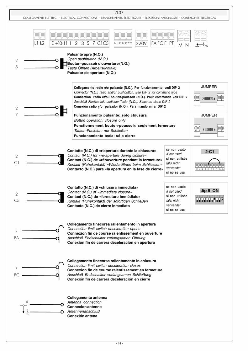
��;�COLLEGAMENTI ELETTRICI - ELECTRICAL CONNECTIONS - BRANCHEMENTS ÉLECTRIQUES - ELEKRISCHE ANSCHLÜSSE - CONEXIONES ELÉCTRICAS
Alimentazione 230V (a.c.)230V (a.c.) power supplyAlimentation 230V (c.a.)Stromversorgung 230V Wechselstrom)Alimentación 230V (a.c.)
Motore 24V(d.c.)24V (d.c.) motorMoteur 24V (c.c.)Motor 24V (Gleichstrom)Motor 24V (d.c.)
Uscita 24V in movimento (es.lampeggiatore - dip 3 OFF)24V output in motion (e.g. flashing light - Pos. B Jumper)Sortie 24V en mouvement (ex. branchement clignotant - Jumper Pos. B)Ausgang 24V in Bewegung (z.B. Blinker-Anschluß - Jumper Pos. B)Salida de 24V en movimento (ej. lámpara intermitente - Jumper Pos. B)
Lampada spia 24V-3W max. "sbarra aperta"24V -3W max. "bar-opened" signal lampLampe-témoin 24V-3W max. "lisse ouverte"Kontrollampe 24V-3W max. "Schranke offen"Lámpara de señal 24V-3W max. "barra abierta"
Alimentazione accessori (max 40W): - 24V (a.c.) con alimentazione a 230V(a.c.) - 24V (d.c.) con alimentazione a 24V (d.c.)Power supply accessories (max. 40W): 24V (a.c.) with power supply at 230V (a.c.) 24V (d.c.) with power supply at 24V (d.c.)Alimentation accessories (max 40W): - 24V (a.c.) avec alimentation à 230V(c.a.) - 24V (d.c.) avec alimentation a 24V (c.c.)Stromversorgung Zubehör (max 40W): - 24V (Wechselstrom) bei Stromversorgung 230V(Wechselstrom) - 24V (Gleichstrom) bei Stromversorgung 24V (Gleichstrom)Alimentación accesorios (max 40W): - 24V (a.c.) con alimentación a 230V(a.c.) - 24V (d.c.) con alimentación a 24V (d.c.)
Pulsante stop (N.C.)Pushbutton stop (N.C.)Bouton-poussoir arrêt (N.F.)Stop-Taste (N.C.)Pulsador de stop (N.C.)
��
��
��
��
N.B. Rispettare la polaritànel collegamento dellefotocellule (TX e RX).
N.B. When connecting thephotocells (TX and RX),
observe the correctpolarities.N.B. Respecter la polaritélors de la connexion desphotocellules (TX et RX).
Anmerkung: beimAnschließen derPhotozellen (TX und RX)
auf die Polung achten.N.B. Respetar la polaridaden la conexión de lasfotocélulas (TX y RX).
�� ��
��
�� � ��
��
��
��
�
�
�� �� � ������ � � ����� �������� ���� �� �� � ��� �� �
��
��
Uscita 24V24V outputSortie 24VAusgang 24VSalida de 24V
in movimento (es.lampeggiatore)During movement (e.g. flashing light)en mouvement (ex. clignotant)während der Bewegungsphase (z.B. Blinker)en movimiento (ej. lámpara intermitente)
DIP 3 OFF
in movimento e in posizione di chiusuraDuring movement and in the closed positionnen mouvement et en position de fermeturewährend der Bewegungsphasen und beiSchließstellungen movimiento y en posición de cierre
DIP 3 ON
��
��
- 14 -
Pulsante apre (N.O.)Open pushbutton (N.O.)Bouton-poussoir d'ouverture (N.O.)Taste Öffnen (Arbeitskontakt)Pulsador de apertura (N.O.)
Collegamento radio e/o pulsante (N.O.)per tipo comando, vedi dip-switch 2Connector (N.O.) radio and/or pushbuttonsee dip-switch 2 for command typeConnection radio et/ou bouton-poussoir (N.O.)pour commande voir dip-switch 2Anschluß Funkkontakt und/oder Taste (N.O.)Steuerart siehe dip-switch 2Conexión radio y/o pulsador (N.O.)para mando mirar dip-switch 2
Contatto (N.C.) di «riapertura durante la chiusura»Contact (N.C.) for «re-aperture during closure»Contact (N.C.) de «réouverture pendant la fermeture»Kontakt (Ruhekontakt) «Wiederöffnen beim Schliessen»Contacto (N.C.) para «la apertura en la fase de cierre»
Contatto (N.C.) di «chiusura immediata»Contact (N.C.) of «immediate closure»Contact (N.C.) de «fermeture immédiate»Kontakt (Ruhekontakt) der sofortigen SchließenContacto (N.C.) de cierre inmediato
Collegamento finecorsa rallentamento in aperturaConnection limit switch deceleration opensConnexion fin de course ralentissement en ouvertureAnschluß Endschallter verlangsamen ÖffnungConexión fin de carrera deceleración en apertura
Collegamento finecorsa rallentamento in chiusuraConnection limit switch deceleration closesConnexion fin de course ralentissement en fermetureAnschluß Endschallter verlangsamen SchließungConexión fin de carrera deceleración en cierre
Collegamento antennaAntenna connectionConnexion antenneAntennenanschlußConexión antena
��
��
�%
%�
�%
%�
��;�� ���#������������������������������������1������$������ �����=����1�����������������2����1�� ��>� ������ ������
��
��
�� �� � ������ � � ����� �������� ���� �� �� � ��� �� �
��
��
��
�;
se non usatoIf not usedsi non utiliséefalls nichtverwendetsi no se usa
E 10 11 1 2 3 5 7 C1 C5
2-C1
se non usatoIf not usedsi non utiliséefalls nichtverwendetsi no se usa
21 3 4 5 6 7 8 9 10ON
dip 8 ON
Collegamento radio e/o pulsante (N.O.). Per funzionamento, vedi DIP 2Connector (N.O.) radio and/or pushbutton. See DIP 2 for command typeConnection radio et/ou bouton-poussoir (N.O.). Pour commande voir DIP 2Anschluß Funkkontakt und/oder Taste (N.O.). Steuerart siehe DIP 2Conexión radio y/o pulsador (N.O.). Para mando mirar DIP 2
JUMPER
Funzionamento pulsante: solo chiusuraButton operation: closure onlyFonctionnement bouton-poussoir: seulement fermetureTasten-Funktion: nur SchließenFuncionamiento tecla: sólo cierre
JUMPER
- 15 -
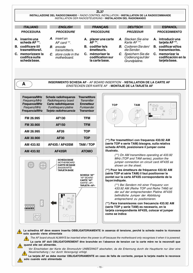
ENGLISHPROCEDURE
A. insert anAF card **.
B. encodetransmitter/s.
C. store code in themotherboard.
FRANÇAISPROCEDURE
A. placer une carteAF **.
B. codifier le/sémetteur/s.
C. mémoriser lacodification surla carte base.
DEUTSCHPROZEDUR
A. Stecken Sie eineKarte AF **.
B. Codieren Sie den/die Sender.
C. Speichern Sie dieCodierung auf derGrundplatine.
ITALIANOPROCEDURA
A. inserire unascheda AF **.
B. codificare il/itrasmettitore/i.
C. memorizzare lacodifica sullascheda base.
ESPANOLPROCEDIMIENTO
A. introducir unatarjeta AF **.
B. codificar el/lostransmisor/es.
C. memorizar lacodificación en latarjeta base.
La schedina AF deve essere inserita OBBLIGATORIAMENTE in assenza di tensione, perché la scheda madre la riconoscesolo quando viene alimentata
The AF board should ALWAYS be inserted when the power is off because the motherboard only recognises it when it is powered.
La carte AF doit OBLIGATOIREMENT être branchée en l’absence de tension car la carte mère ne la reconnaît quequand elle est alimentée.
Vor Einschieben der Karte die Stromzufuhr UNBEDINGT abschalten, da die Erkennung durch die Hauptkarte nur über eineNeueinschaltung ( nur durch Versorgung) erfolgt.
La tarjeta AF se debe montar OBLIGATORIAMENTE en caso de falta de corriente, porque la tarjeta madre la reconocesólo cuando está alimentada
(**) Per trasmettitori con frequenza 433.92 AM(serie TOP e serie TAM) bisogna, sulla relativascheda AF43S, posizionare il jumper comeillustrato.
(**) On AM transmitters operating at 433.92MHz (TOP and TAM series), position thejumper connection on circuit card AF43S asshown on the sheet.
(**) Pour les émetteurs de fréquence 433.92 AM(série TOP et série TAM) il faut positionner lepontet sur la carte AF43S correspondante de lafaçon indiquée.
(**) Bei Sendern mit einer Frequenz von433.92 AM (Reihe TOP und Reihe TAM) istder auf der entsprechenden Platine AF43Sbefindliche Jumper der Abbildungentsprechend zu positionieren.
(**) Para transmisores con frecuencia 433.92 AM(serie TOP y serie TAM) es necesario, en latarjeta corespondiente AF43S, colocar el jumpercomo se indica
ZL37INSTALLAZIONE DEL RADIOCOMANDO - RADIO CONTROL INSTALLATION - INSTALLATION DE LA RADIOCOMMANDE
INSTALLATION DER RADIOSTEUERUNG - INSTALACIÓN DEL RADIOMANDO
INSERIMENTO SCHEDA AF - AF BOARD INSERTION - NSTALLATION DE LA CARTE AF EINSTECKEN DER KARTE AF - MONTAJE DE LA TARJETA AFA
SCHEDA BASEMOTHERBOARDCARTE DE BASEBASISKARTETARJETA BASE
SCHEDA "AF""AF" BOARDCARTE "AF"KARTE «AF»TARJETA «AF»
5 6 7 8 9 10
Frequenza/MHzFrequency/MHzFrequence/MHzFrequenz/MHz
Frequencia/MHz
Scheda radiofrequenzaRadiofrequency boardCarte radiofréquenceFunkfrequenz-platine
Tarjeta radiofrecuencia
TrasmettitoreTransmitterEmmetteurFunksenderTransmisor
FM 26.995 AF130 TFM
FM 30.900 AF150 TFM
AM 26.995 AF26 TOP
AM 30.900 AF30 TOP
AM 433.92 AF43S / AF43SM TAM / TOP
AM 433.92 AF43SR ATOMO
TOP TAM

- 16 -
impostare il codice sul dip-switch C e il canale su D (P1=CH1 eP2=CH2, impostazione di default)
set the code to dip-switch C and channel to D (P1=CH1 and P2=CH2,default setting)
saisir le code sur le commutateur dip C et le canal sur D (P1=CH1 etP2=CH2, saisie de défaut)
Stellen Sie den Code auf den Dip-Switch C und den Kanal auf D(P1=CH1 und P2=CH2; Grundeinstellung).
plantear el código en el dip-switch C y el canal en D (P1=CH1 yP2=CH2, planteamiento por defecto)
T432M - T312M
1 2 3 4 5 6 7 8 9 10
1 2 3 4
C
DP1 P2
P2
CH1 CH2 CH3 CH4
P1
CH1 CH2 CH3 CH4
1 2 3 4 1 2 3 4 1 2 3 41 2 3 4
1 2 3 4 1 2 3 4 1 2 3 4 1 2 3 4
vedi istruzioni su confezionesee instructions on pack
voir instructions sur l'emballageSiehe Anleitungen auf der Packung.
ver instrucciones en el embalaje
T432S / T432SA
CODIFICA TRASMETTITORI - TRANSMITTER ENCODING - CODIFICATION DES EMETTEURSCODIERUNG DER SENDER - CODIFICACIÓN TRANSMISORESB
CODIFICA TRASMETTITORI - TRANSMITTER ENCODING - CODIFICATION DES EMETTEURSCODIERUNG DER SENDER - CODIFICACIÓN TRANSMISORESB
TOP
AT01 - AT02
CODIFICA TRASMETTITORI - TRANSMITTER ENCODING - CODIFICATION DES EMETTEURSCODIERUNG DER SENDER - CODIFICACIÓN TRANSMISORESB
ATOMO
vedi foglio istruzioni inserito nella confezionedella scheda AF43SR
see instruction sheet inside the pack ofAF43SR circuit card
voir les instructions qui se trouve dansl'emballage de la carte AF43SR
Siehe Anleitungen, die der Packung beiliegender Platine AF43SR
ver hoja de instrucciones adjunta en elembalaje de la tarjeta AF43SR
vedi foglio istruzioni inseritonella confezione
see instruction sheet insidethe pack
voir la notice d'instructionsqui se trouve dans
l'emballageSiehe Anleitungen, die der
Packung beiliegen.ver hoja de instrucciones
adjunta en el embalaje
TAM
T132T134T138
T152T154T158
T432T434T438
TFM
T434M - T314M
impostare solo ilcodice
set code onlyne saisir que le code
Stellen Sie nur denCode ein.
plantear sólo el código
P1=CH1P2=CH2P3=CH3P4=CH4
1 2 3 4 5 6 7 8 9 10
C
P1 P2
P3 P4

- 17 -
PROCEDURA COMUNE DI CODIFICA
T262M-T264M-T2622MT302M-T304M-T3022M
1.segnare un codice (anche per archivio)2.inserire jumper codifica J3.memorizzarlo4.disinserire jumper J
STANDARD ENCODING PROCEDURE
T262M-T264M-T2622MT302M-T304M-T3022M
1.assign a code (also on file)2.connect encoding jumper J3.register code4.disconnect jumper J
PROCEDURE COMMUNE DE CODIFICATION
T262M-T264M-T2622MT302M-T304M-T3022M
1.taper un code (également pour lesarchives)
2.placer un cavalier de codification J3.mémoriser le code4.enlever le cavalier J
ANLEITUNGEN ZUR CODIERUNG
T262M-T264M-T2622MT302M-T304M-T3022M
1.Ordnen Sie einen Code zu (auch für dasArchiv).
2.Schalten Sie den Codierungs-Jumper J ein.3.Speichern Sie den Code.4.Schalten Sie den Jumper J wieder aus.
PROCEDIMIENTO COMÚN DE CODIFICACIÓN
T262M-T264M-T2622MT302M-T304M-T3022M
1.marcar un código (también para elarchivo)
2.conectar un jumper codificación J3.registrar el código4.desconectar jumper J
La prima codifica deve essere effettuata mantenendo i jumperposizionati per i canali 1 e 2 come da fig. A; per eventuali esuccessive impostazioni su canali diversi vedi fig. B
The first encoding operation must be carried out whilst keeping thejumpers positioned for channels 1 and 2 as per fig. A; see fig. B forany subsequent settings on different channels.
La première codification doit être effectuée en maintenant lescavaliers en position pour les canaux 1 et 2, comme d'après la fig.A; pour des saisies successives éventuelles sur des canauxdifférents, voir fig. B
Für die erste Codierung muß der Jumper auf den Kanälen 1 und 2positioniert bleiben (siehe Abb. A). Für eventuelle weitere oderspätere Einstellungen auf anderen Kanälen halten Sie sich bitte anAbb. B.
La primera codificación tiene que efectuarse manteniendo losjumper conectados para los canales 1 y 2 como se ilustra en lafig. A; para planteamientos posteriores en canales distintos ver lafig. B
T262M - T302M
P1 P2
J
P1=CH1P2=CH2
fig.A
fig. B
P1=CH1 - P2=CH4
P1=CH1 - P2=CH3 P1=CH3 - P2=CH2
P1=CH3 - P2=CH4
P1 P2
P3 P4
P1=CH1 - P2=CH2P3=CH3 - P4=CH4
J
T264M - T304M
P1 P2
T2622M - T3022M
2° codice/codice/codice/codice/codice
ON
OFFP1P2
P3=CH1P4=CH2
J
1° codice/codicecodice/codice/codice
P1=CH1P2=CH2
J
4.
J
premere in sequenza P1 o P2 per registrare ilcodice; al decimo impulso un doppio suonoconfermerà l'avvenuta registrazione
Press P1 or P2 in sequence in order to registerthe code; at the tenth pulse, a double beep willconfirm that registration has occurred
appuyer en séquence sur P1 ou P2 pourmémoriser le code; à la dixième impulsion, unedouble sonnerie confirme que le code a étémémorisé
Drücken Sie nacheinander P1 oder P2, um denCode zu speichern. Nach dem zehnten Impulssignalisiert ein doppelter Piepton, daß der Codegespeichert worden ist.
oprimir repetidamente P1 ó P2 para registrar elcódigo; con el décimo impulso un doblesonido señalará que el registro se haefectuado.
P1=OFF P2=ON
3.
2.
JON
OFFP1
P2
codice/codice/codice/codice/codice
1.
CODIFICA TRASMETTITORI - TRANSMITTER ENCODING - CODIFICATION DES EMETTEURS
CODIERUNG DER SENDER - CODIFICACIÓN TRANSMISORES
TOP QUARZATI - QUARTZ - AU QUARTZ - QUARTZGENAUE - CUARZO
B

- 18 -
ITALIANO
-Tenere premuto iltasto "CH1" sullascheda base (il leddi segnalazionelampeggia), con untasto del trasmettito-re s'invia il codice, illed rimarrà acceso asegnalare l'avvenutamemorizzazione(vedi fig.1).
DEUTSCH
-Halten Sie die TasteCH1 an derBasiskarte gedrückt(die Kontrolleuchteblinkt). Senden Sieden Code mit einerTaste vom Sender.Der Kontrolleuchtebleibt jetzt an undzeigt dadurch daserfolgte Speichern an(Abb.1).
ESPANOL
-Manteneroprimida la tecla"CH1" en la tarjetabase (el led deseñalizaciónparpadea), con unatecla deltransmisor seenvía el código, elled permaneceencendido paraindicar que elalmacenamendose ha efectuado(fig.1).
ENGLISH
-Keep the CH1 keypressed on the basecard (the signal LEDwill flash), and with akey on the transmitterthe code is sent, theLED will remain lit tosignal the successfulsaving of the code(figure 1).
FRANÇAIS
-Appuyer sur latouche "CH1" sur lacarte de base (le ledde signalisationclignote), avec unetouche du emetteuron envoie le code, leled restera allumépour signaler que lamémorisation s'esteffectuèe (fig.1).
MEMORIZZAZIONE CODICE - CODE STORAGE - MEMORISATION DU CODE
SPEICHERN VOM CODE - MEMORIZACIÓN CÓDIGOC
N.B. Se in seguito si vuol cambiare codice ai propritrasmettitori, basta ripetere la sequenza descritta.
N.B. If you wish to change the code on your transmittersin the future, simply repeat the procedure describedabove.
N.B.: Si, successivement, on veut changer le codedes émetteur, il suffit de répéter la séquence décriteci-dessus.
HINWEIS: bei eventuell erwünschter Sendercodeänderung ist der beschriebene Vorgang zuwiederholen.
NOTA: Si posteriormente se quisiera cambiar elcódigo de los propios transmisores, sólo hay querepetir la secuencia descrita.
Fig./Abb. 1
Scheda radiofrequenzaRadiofrequency boardCarte radiofrèquenceFunkfrequenze-PlatineTarjeta radiofrecuencia
�$
LED di segnalazione codice radioRadio code signal LEDLED de signalisation code radioFunkcode-AnzeigeleuchtdiodeLED de señal código radio

- 19 -
REGOLAZIONE DI VELOCITÀ DI CHIUSURA/APERTURTA E DI RALLENTAMENTO / ADJUSTMENT OF CLOSURE/APER-TURE SPEED AND DECELERATION SPEED
RÉGLAGE DE LA VITESSE DE FERMETURE/OUVERTURE ET DE RALENTISSEMENT / EINSTELLUNG DER ÖFFNUNGS-/SCHLIESSGESCHWINDIGKEIT UND LANGSAMLAUFGESCHWINDIGKEIT / REGULACION VELOCIDAD CIERRE/APERTU-
RA Y DE DECELERACION
Es: velocità di apertura e chiusura max. - rallentamento max (vedidisegno a lato)
Ex: max. speed during opening and closing - max. deceleration (seedrawing opposite)Ex: vitesse d'ouverture et fermeture max. - ralentissement max(dessin ci-contre)
Beispiel: Max. Öffnungs- und Schließgeschwindigkeit -Max. Leufverlangsamung (siehe Abbildung nebenan)
Ej: velocidad de apertura y cierre màx. - deceleración màx (dibujoal lado)
Per la regolazione della velocità e del rallentamento, spostare i connettori faston "A" e "B" nei morsettiindicati.
To set the speed and deceleration, move faston connectors "A" and "B" onto the indicated terminals.Pour la réglage de la vitesse et de ralentissement, déplacer le connecteurs faston "A" et "B" sur les bornesindiquées.
Zur Einstellung der Geschwindigkeit und der Leufverlangsamung die Faston-Verbinder "A" und "B" indie gewünschte Stellung bringen.Para la regulación de la velocidad y de deceleración, desplazar los conectores faston "A" y "B" en losbornes indicados.
�
�
?�??�?
��� �!" �#$ �#$ ���
�+3-.&*2�3��$�&*+00+���/',��+3-.&,(,
�(33+)*(8+)*-��/�)�"( !#&�(3+)*&00+8+)*���/',��4&('5��+.+3+'(.&9)

- 20 -
Tutti i dati sono stati controllati con lamassima cura. Non ci assumiamo co-munque alcuna responsabilità pereventuali errori od omissioni.
All data checked with the maximum care.However, no liability is accepted for anyerror or omission.
Toutes les données ont été contrôléestrès soigneusement. Nous n’assumonsde toute façon aucune responsabilitépour les erreurs ou omissionséventuelles.
Die Daten wurden mit höchster Sorgfaltgeprü f t . Für eventuel le Fehler oderAuslassungen übernehmen wir keineHaftung.
Todos los datos se han controlado conla máxima atención. No obstante nonos responsabilizamos de los posibleserrores u omisiones.
CANCELLI AUTOMATICI
CAME LOMBARDIA S.R.L.______COLOGNO M. (MI) (+39) 02 26708293 (+39) 02 25490288
CAME SUD S.R.L. ___________________NAPOLI (+39) 081 752445 (+39) 081 7529109
CAME (AMERICA) L.L.C.____________MIAMI (FL) (+1) 305 5930227 (+1) 305 5939823
CAME AUTOMATISMOS S.A__________MADRID (+34) 091 5285009 (+34) 091 4685442
CAME BELGIUM__________________LESSINES (+32) 068 333014 (+32) 068 338019
CAME FRANCE S.A.____NANTERRE CEDEX (PARIS) (+33) 01 46130505 (+33) 01 46130500
CAME GMBH________KORNTAL BEI (STUTTGART) (+49) 07 11839590 (+49) 07 118395925
CAME GMBH____________SEEFELD BEI (BERLIN) (+49) 03 33988390 (+49) 03 339885508
CAME PL SP.ZO.O______________WARSZAWA (+48) 022 8699933 (+48) 022 6399933
CAME UNITED KINGDOM LTD___NOTTINGHAM (+44) 01159 387200 (+44) 01159 382694
CAME CANCELLI AUTOMATICI S.P.A.DOSSON DI CASIER (TREVISO)
(+39) 0422 490960 (+39) 0422 490944
SISTEMA QUALITÀCERTIFICATO
ASSISTENZA TECNICA
NUMERO VERDE
800 295830
WEB
www.came.it E-MAIL
COLLEGAMENTO PER 2 MOTORI ABBINATI CON COMANDO UNICO / CONNECTIONS FOR 2 COMBINED MOTORSCONTROLLED TOGETHER
CONNEXIONS POUR 2 MOTEURS ACCOUPLÉS AVEC COMMANDE INIQUE / ANSCHLUSS FÜR 2PARALLELGESCHALTETE MOTOREN MIT GEMEINSAMER STEUERUNG / CONEXION PARA 2 MOTORES
ACOPLADOS CON MANDO UNICO
- Coordinare il senso di marcia delle due barriere, modificando la rotazione di un motore;- In uno dei due quadri, inserire il dip 7 in ON per renderlo motore pilotato (slave).
- Synchronize the direction of movement of the two barriers by adjusting the direction of movement of one of themotors;
- On one of the two control panels, set Dip 7 to ON in order to select the motor controlled externally (slave).- Coordonner le sens du mouvement des deux barrières en modifiant la rotation d'un moteur;- Sur l'une des deux armoires, placer le dip-switch 7 sur ON pour désigner le moteur correspondant commepiloté (slave).
- Die Laufrichtung der beiden Schranken durch Änderung der Motordrehrichtung koordinieren;- Auf einem der beiden Steuergeräte den Dip-Switch 7 auf "ON" stellen, wodurch dieser Motor zum gesteuerter
Motor (Slave) wird.- Coordinar el sentido de marcha de las dos barras, modificando la rotación de un motor;- En uno de los dos cuadros, introducir el dip 7 en ON para hacerlo motor pilotado (slave).
Morsettiera 2° motore slaveSlave motor 2° terminal block
Plaque à bornes du 2° moteur slaveKlemmbrett 2° Slavemotor
Cuadro de bornes 2° motor slave
- Eseguire solo sulla morsettiera pilota i collegamenti elettrici predisposti normalmente;- Collegare i due quadri attraverso i morsetti di interblocco come da figura.
- Wire the electrical connections only on the terminal board for the pilot motor in the normal.- Connect the two control panels using the interlock terminals as shown in the figure.
- Effectuer seulement sur la plaque à borne pilote les branchements électriques habituellement prévus;- Brancher les deux armoires aux bornes de blocage interdépendent de la façon indiquée sur la figure.
- Nur auf der Mastermotor-Klemmleiste die normalerweise vorgesehenen elektrischen Anschlüsseausführen.
- Die beiden Steuergeräte über die Verblockungsklemmen miteinander verbinden (siehe Abbildung).- Efectuar sólo en la caja de bornes piloto las conexiones eléctricas predispuestas normalmente;- Conectar los dos cuadros a travs de los bornes de interbloqueo como indicado en la figura.
Morsettiera 1° motore (pilota)(pilot) motor 1° terminal block
Plaque à bornes du 1° moteur (pilote)Klemmbrett 1° Motor (Steuemotor)
Cuadro de bornes 1° motor (piloto)