AUDIO INTERFACE UNIT N-8000AF€¦ · d’alimentation endommagé peut présenter un risque...
16
INSTALLATION MANUAL AUDIO INTERFACE UNIT N-8000AF Thank you for purchasing TOA’s Audio Interface Unit. Please carefully follow the instructions in this manual to ensure long, trouble-free use of your equipment.
Transcript of AUDIO INTERFACE UNIT N-8000AF€¦ · d’alimentation endommagé peut présenter un risque...

INSTALLATION MANUAL
AUDIO INTERFACE UNIT N-8000AF
Thank you for purchasing TOA’s Audio Interface Unit. Please carefully follow the instructions in this manual to ensure long, trouble-free use of your equipment.
2
TABLE OF CONTENTS
1. SAFETY PRECAUTIONS ............................................................................. 3
2. GENERAL DESCRIPTION .......................................................................... 6
3. FEATURES ............................................................................................................ 6
4. NOMENCLATURE AND FUNCTIONS ................................................. 7Front ............................................................................................................................. 7Rear ............................................................................................................................. 7
5. INSTALLATION .................................................................................................. 85.1. Equipment Rack Mounting .................................................................................... 8
5.1.1. Setting space ............................................................................................... 85.1.2. Mounting on the rack ................................................................................... 9
5.2. Desk-Top Installation ........................................................................................... 105.3. Wall Mounting ..................................................................................................... 10
6. WIRING .................................................................................................................. 126.1. Connection Diagram ............................................................................................ 126.2. Type of Cable ...................................................................................................... 146.3. Removable terminal plug connection ................................................................. 14
7. ACCESSORIES ................................................................................................. 15
8. OPTIONAL PRODUCTS ............................................................................. 15

3
1. SAFETY PRECAUTIONS• Before installationoruse,besure tocarefully readall the instructions in thissection forcorrectandsafe
operation.• Besuretofollowalltheprecautionaryinstructionsinthissection,whichcontainimportantwarningsand/or
cautions regarding safety.• Afterreading,keepthismanualhandyforfuturereference.
Safety Symbol and Message Conventions Safety symbols and messages described below are used in this manual to prevent bodily injury and property damage which could result from mishandling. Before operating your product, read this manual first andunderstand the safety symbols and messages so you are thoroughly aware of the potential safety hazards.
WARNINGWhen Installing the Unit
• Donotexpose theunit to rainor anenvironmentwhere it may be splashed by water or other liquids, asdoingsomayresultinfireorelectricshock.
• Use the unit only with the voltage specified onthe unit. Using a voltage higher than that which is specifiedmayresultinfireorelectricshock.
• Do not cut, kink, otherwise damage nor modifythe power supply cord. In addition, avoid using the powercordincloseproximitytoheaters,andneverplace heavy objects -- including the unit itself -- on the power cord, as doing somay result in fire orelectric shock.
• Avoid installing or mounting the unit in unstablelocations, such as on a rickety table or a slanted surface. Doing so may result in the unit falling downandcausingpersonal injuryand/orpropertydamage.
• Installtheunitonlyinalocationthatcanstructurallysupport the weight of the unit and the mounting bracket. Doing otherwise may result in the unit falling down and causing personal injury and/orproperty damage.
When the Unit is in Use
• Should the following irregularity be found duringuse, immediately disconnect the power supply plug from the AC outlet and contact your nearest TOA dealer. Make no further attempt to operate the unit in thisconditionas thismaycausefireorelectricshock.
· If you detect smoke or a strange smell coming from the unit
· If water or any metallic object gets into the unit · Ifthepowersupplycordisdamaged(exposureof
the core, disconnection, etc.)· If it is malfunctioning (no tone sounds.)
• Topreventafireorelectricshock,neveropennorremove the unit case as there are high voltage components inside the unit. Refer all servicing to qualifiedservicepersonnel.
• Donotinsertnordropmetallicobjectsorflammablematerials in the ventilation slots of the unit's cover, asthismayresultinfireorelectricshock.
• Donottouchaplugduringthunderandlightning,asthis may result in electric shock.
CAUTIONWhen Installing the Unit
• Never plug in nor remove the power supply plugwith wet hands, as doing so may cause electric shock.
• Whenunpluggingthepowersupplycord,besuretograsp the power supply plug; never pull on the cord itself. Operating the unit with a damaged power supply cord may cause a fire or electric shock.
• Besuretofollowtheinstructionsbelowwhenrack-mounting the unit. Failure to do so may cause a fire or personal injury.
· Installtheequipmentrackonastable,hardfloor.Fixitwithanchorboltsortakeotherarrangementsto prevent it from falling down.
Indicates a potentially hazardous situation which, if mishandled, could result in death or serious personal injury.
Indicates a potentially hazardous situation which, if mishandled, could resultinmoderateorminorpersonalinjury,and/orpropertydamage.
WARNINGCAUTION
4
· When connecting the unit's power cord to an AC outlet, use the AC outlet with current capacity allowable to the unit.
· The supplied rack-mounting screws can be used for the TOA equipment rack only. Do not use them for other racks.
When the Unit is in Use
• Donotplaceheavyobjectsontheunitasthismaycause it to fall or break which may result in personal injury and/or property damage. In addition, theobject itself may fall off and cause injury and/ordamage.
• Donotstandorsiton,norhangdownfromtheunitas this may cause it to fall down or drop, resulting in personalinjuryand/orpropertydamage.
CONSEILS DE SÉCURITÉ• Avant l’installation ou l’utilisation, lire attentivement l’ensemble des instructions de cette section pour un
fonctionnement correct et sûr.• Veilleràrespecterlesprécautionsrecommandéesdanscettesection,laquellecontientdesmisesengardeet/ouprécautionsimportantesenmatièredesécurité.
• Aprèslecture,conservercemanuelàportéedemainpourconsultationultérieure.
Symboles de sécurité et conventionsLessymbolesetmessagesdesécuritédécritsci-dessoussontutilisésdanscettenoticepourprévenir toutdommagecorporeloumatérielpouvantrésulterd’unemauvaiseutilisation.Lireattentivementcettenoticepourcomprendreparfaitementlessymbolesetmessagesdesécuritéafindeprévenirtoutrisqueéventuel.
Indique une situation risquant d’entraîner des blessures graves, voire la mort, en cas de mauvaise manipulation.
Indique une situation risquant d’entraîner des blessures moyennementgravesoumineures,et/oudesdommagesmatériels.
AVERTISSEMENTATTENTION
AVERTISSEMENTLors de l’installation de l’appareil
• Nepasexposerl’appareilàlapluieetleprotégerdetoutcontactavecdel’eauoud’autresliquidesafind’éviterunincendieouuneélectrocution.
• Utilisez l’appareil uniquement avec la tensionspécifiéesurlechargeur.L’utilisationd’unetensionsupérieure à celle spécifiée peut être à l’origined’unincendieoud’uneélectrocution.
• Nepascouper,entortiller,modifierouendommagerlecordond’alimentation.Enoutre,éviterd’utiliserlecordond’alimentationàproximitéd’unradiateuretne jamais placer d’objets lourds (y compris l’appareil lui-même) sur le cordon d’alimentation, car ceciprésenteunrisqued’incendieoud’électrocution.
• Évitezd’installeroudemonterl’unitédansunendroitinstable, tel qu’une table bancale ou une surface inclinée pour prévenir toute chute susceptiblede provoquer une blessure corporelle et/ou unedégradationmatérielle.
• Installer l’unité dans un endroit structurellementcapable de soutenir le poids de l’appareil et de la patte de montage.
L’appareil pourrait tomber et provoquer des blessures corporelleset/oudesdommagesmatériels.
Pendant l’utilisation de l’appareil
• En cas de survenue des irrégularités suivantespendant l’utilisation,débrancher immédiatement lafiche du cordon d’alimentation de la prise secteur et contacter le représentant TOA le plus proche.Ne pas essayer pas d’utiliser l’appareil dans cesconditions sous peine de provoquer un incendie ou uneélectrocution.·Détection de fumée ou d’une odeur inhabituelleémanantdel’appareil.
· Pénétration d’eau ou d’un objetmétallique dansl’appareil
· Dégradation du cordon d’alimentation (âme ducâbledénudée,déconnexionetc.).
· Dysfonctionnement(absencedetonalité).

5
• Pourempêcherun incendieouuneélectrocution,ne jamais ouvrir ni ne retirer le boîtier de l’appareil, enraisondelaprésencedepiècesàhautetension.Lamaintenancedel’appareildoitêtreconfiéeàuntechnicienaprès-ventequalifié.
• Nepasinsérernilaissertomberd’objetsmétalliquesoudematériaux inflammablesdans leséventsdeventilation du capot de l’appareil sous peine de provoquerunincendieouuneélectrocution.
• Ne pas toucher la fiche du cordon d’alimentationpendantunorage-Risqued’électrocution.
ATTENTIONLors de l’installation de l’appareil
• Ne jamais brancher, ni débrancher la fiche ducordon d’alimentation avec les mains mouillées.Risqued’électrocution.
• Pour débrancher le cordon d’alimentation, veilleràletenirparsafiche;nejamaistirerdirectementle cordon. Utiliser l’appareil avec un cordon d’alimentation endommagé peut présenter unrisqued’incendieoud’électrocution.
• Respecterlesinstructionsci-dessouspourmonterl’appareilenbâti.Risqued’incendieoudeblessurecorporelle.· Installerlebâtisurunsolstable.Lefixeràl’aide
de boulons d’ancrage ou prendre des mesures pourempêcherqu’ilnechute.
· Pourbrancherlecordond’alimentationàunepriseCA,vérifierl’intensitémaximaledel’appareil.
· Les vis de montage en bâti fournies peuventseulementêtreutiliséespourlebâtidel’équipementTOA.Nepaslesutiliserpourd’autresbâtis.
Pendant l’utilisation de l’appareil
• Ne pas placer d’objets lourds sur l’appareil souspeine de le faire tomber ou de le rompre, ce qui présenteunrisquedeblessurescorporelleset/oude dommages matériels. Par ailleurs, l’objet lui-mêmepeuttomberetprovoquerdesblessureset/oudégâts.
• Ne pas placer d’objets lourds sur l’appareil souspeinedelefairetomber,cequiprésenteunrisquede blessures corporelles et/ou de dommagesmatériels.
6
3. FEATURES• Exchanges,IPstationsandvariouskindsofinterfaceunitscanbedistributedoveradatacommunications
network.• Canbeconnectedtoanexistinglocalareanetwork(LAN)orwide-areanetwork(WAN).• Thededicatedsoftwareprogramenablescentralizedcontrolwithapersonalcomputer.• Systemmaintenance(verifyingoperationlogandLinesupervision)canalsobeperformedwithapersonal
computer and Internet browser.• TheunitcaninterlockwithanelectroniclocksystemorCCTVsurveillancesystembywayofcontactinput/
output control function.
CARACTÉRISTIQUES
• Unréseaudecommunicationdedonnéespermetlaconnexiondecentraux,destationsIPetdedifférentstypes d’interfaces.
• Peutêtreconnectéàunréseaulocal(LAN)ouétendu(WAN)existant.• Logicieldédiépermettantuncontrôlecentraliséàpartird’unPC.• La maintenance du système (vérification du journal d’opérations et supervision des lignes) peut aussi
intervenir via un ordinateur personnel et un navigateur Internet. • Ilestpossibled’assureruneinterfaceentrel’unitéetunsystèmedeverrouillageélectroniqueouunsystèmedecaméradesurveillancevialafonctiondecontrôledel’entrée/sortiedecontact.
2. GENERAL DESCRIPTIONTOA's N-8000AF is Audio interface unit used for the N-8000 Series Packet IntercomSystem (IP networkcompatible intercom) employing packet audio technology*.It has an analog audio input and output, a time synchronization contact input, and each 8 contact inputs and outputs.ConnectingtheunittotheLANpermitsrecordingofconversations,chimebroadcastatregularintervals(timesignal) and paging broadcast to be realized.
* Technology related to audio transmission over a network.
WarningThis is a class A product. In a domestic environment this product may cause radio interference in which case the user may be required to take adequate measures.
DESCRIPTION GÉNÉRALEL’unitéN-8000AFdeTOAestl’interfaceaudioutiliséepourlesystèmedepaquetintercomdessériesN-8000(intercomcompatibleavecunréseauIP)utilisantunetechnologiedepaquetaudio*.Elleestdotéed’uneentréeetd’unesortieaudioanalogiques,d’uneentréedecontactdesynchronisationainsiqued’entréesetdesortieschacuneà8contacts.Le raccordement de l’unité à un LAN permet d’enregistrer des conversations, de diffuser une sonnerie àintervallesréguliers(signalhoraire)etd’envoyerunenotification.
*Technologiedetransmissionaudiosurunréseau.
Avertissement CetéquipementestunproduitdeclasseA.Enenvironnementdomestique,ceproduitpeutprovoquerdesinterférencesradio.
7
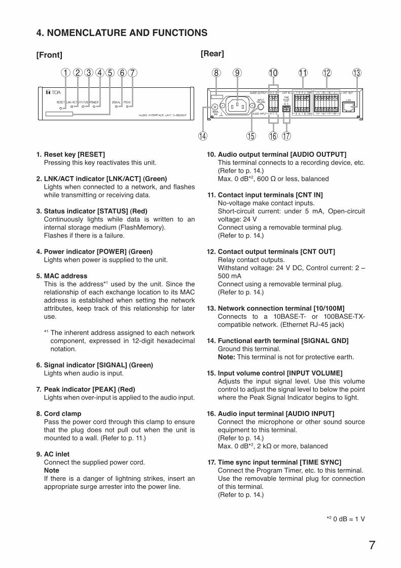
4. NOMENCLATURE AND FUNCTIONS
[Front]
1 2 3 4 5 6 7 8 9 10 11 12 13
14 15 16 17
1. Reset key [RESET]Pressing this key reactivates this unit.
2. LNK/ACT indicator [LNK/ACT] (Green)Lightswhenconnectedtoanetwork,andflasheswhile transmitting or receiving data.
3. Status indicator [STATUS] (Red)Continuously lights while data is written to an internal storage medium (FlashMemory).Flashes if there is a failure.
4. Power indicator [POWER] (Green)Lights when power is supplied to the unit.
5. MAC addressThis is the address*1 used by the unit. Since the relationshipofeachexchangelocationtoitsMACaddress is established when setting the network attributes, keep track of this relationship for later use.
*1 The inherent address assigned to each network component, expressed in 12-digit hexadecimalnotation.
6. Signal indicator [SIGNAL] (Green)Lights when audio is input.
7. Peak indicator [PEAK] (Red)Lights when over-input is applied to the audio input.
8. Cord clampPass the power cord through this clamp to ensure that the plug does not pull out when the unit is mounted to a wall. (Refer to p. 11.)
9. AC inletConnect the supplied power cord.NoteIf there is a danger of lightning strikes, insert an appropriate surge arrester into the power line.
10. Audio output terminal [AUDIO OUTPUT]This terminal connects to a recording device, etc.(Refer to p. 14.) Max.0dB*2,600Ωorless,balanced
11. Contact input terminals [CNT IN]No-voltagemakecontactinputs.Short-circuit current: under 5 mA, Open-circuit voltage:24VConnect using a removable terminal plug. (Refer to p. 14.)
12. Contact output terminals [CNT OUT]Relay contact outputs.Withstandvoltage:24VDC,Controlcurrent:2–500 mA Connect using a removable terminal plug. (Refer to p. 14.)
13. Network connection terminal [10/100M]Connects to a 10BASE-T- or 100BASE-TX-compatible network. (Ethernet RJ-45 jack)
14. Functional earth terminal [SIGNAL GND]Ground this terminal.Note: This terminal is not for protective earth.
15. Input volume control [INPUT VOLUME]Adjusts the input signal level. Use this volume control to adjust the signal level to below the point where the Peak Signal Indicator begins to light.
16. Audio input terminal [AUDIO INPUT]Connect the microphone or other sound source equipment to this terminal. (Refer to p. 14.) Max.0dB*2,2kΩormore,balanced
17. Time sync input terminal [TIME SYNC]Connect the Program Timer, etc. to this terminal. Use the removable terminal plug for connection of this terminal. (Refer to p. 14.)
*20dB=1V
[Rear]
8
5. INSTALLATIONTheN-8000AFcanbeinstalledinanyofthreeways:Equipment rack mounting, Desk-top installation, and Wall mounting.
5.1. Equipment Rack Mounting
A) Elevated Operating Ambient - If installed in a closed or multi-unit rack assembly, the operating ambient temperature of the rack environment may be greater than room ambient. Therefore, consideration should begiventoinstallingtheequipmentinanenvironmentcompatiblewiththemaximumambienttemperature(Tma) specified by the manufacturer.
B)ReducedAirFlow-Installationoftheequipmentinarackshouldbesuchthattheamountofairflowrequiredfor safe operation of the equipment is not compromised.
C) Mechanical Loading - Mounting of the equipment in the rack should be such that a hazardous condition is not achieved due to uneven mechanical loading.
D) Circuit Overloading - Consideration should be given to the connection of the equipment to the supply circuit and the effect that overloading of the circuits might have on overcurrent protection and supply wiring. Appropriate consideration of equipment nameplate ratings should be used when addressing this concern.
E) Reliable Earthing - Reliable earthing of rack-mounted equipment should be maintained. Particular attention should be given to supply connections other than direct connections to the branch circuit (e.g. use of power strips)."
A) Température ambiante élevée - si l’appareil est installé dans un bâti fermé ou en même temps qued’autresappareils,latempératureàl’intérieurrisquededevenirsupérieureàlatempératureambiante.Parconséquent,veilleràinstallerl’équipementdansunenvironnementcompatibleàlatempératureambiantemaximumspécifiéeparlefabricant.
B) Débitd’airréduit-L’installationdel’équipementenbâtinedoitpascompromettreledébitd’airnécessaireàuneutilisationsûredel’équipement.
C) Chargemécanique-Lemontagedel’équipementenbâtinedoitpasentraînerdedangerdûàunesurchargemécaniqueinégale.
D) Surcharge du circuit - rester vigilant lors de la connexion de l’équipement au circuit d’alimentation etaux conséquences d’une surcharge des circuits sur la protection contre les surintensités et les câblesd’alimentation. Tenir compte des indications de la plaque nominale de l’appareil.
E) Veiller à toujours garantir l’intégrité de la prise demise à la terre. Faire particulièrement attention auxconnexionsd’alimentationendehorsdesbranchementsdirectsaucircuitdedérivation(parexempleàl’aidede multiprises).
TheN-8000AFcanbemountedontheCR-273orCR-413orstandardEIA19"Equipmentrack.For the CR-273 and CR-413 Equipment rack assembly, read the installation manual supplied with the rack.
NoteWheninstallingtheN-8000AF,laytheequipmentrackdownface-uptodoinstallationworksafely.
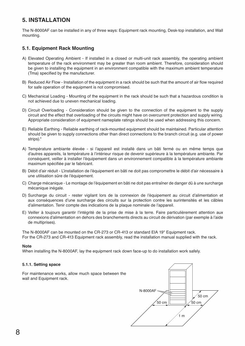
N-8000AF
50 cm 50 cm
1 m
50 cm
5.1.1. Setting space
For maintenance works, allow much space between the wall and Equipment rack.

9
5.1.2. Mounting on the rackMontage en bâti
Use the optional mounting hardware set when installing the unit in an equipment rack.Utilisezlematérieldemontageenoptionpourinstallerl’unitéenbâti.
• Use the optional MB-15B-BK hardware set when mounting a single unit.• Utilisez le matériel MB-15B-BK en option pour le montage d’une seule unité.
Tapping screw 3 x 8*1
Rack mounting bracket*1
Rack mounting screw 5 x 12*1 Fiber washer (for M5)*1
Tapping screw 3 x 14*1
Tapping screw 3 x 8*1
N-8000AFBlank bracket*1
Vis-taraud 3 x 14*1
Vis-taraud 3 x 8*1
Patte vierge*1
Vis-taraud 3 x 8*1
Patte de montage*1
Rondelle en fibre (pour M5)*1Vis de montage en bâti 5 x 12*1
Tapping screw 3 x 14*2
Rack mounting bracket*2
Rack mounting screw 5 x 12*2
Fiber washer (for M5)*2
Tapping screw 3 x 14*2
Coupler*2 Machine screw 3 x 12*2
N-8000AF
N-8000AF
Vis-taraud 3 x 14*2
Rondelle en fibre (pour M5)*2
Vis de montage en bâti 5 x 12*2
Vis de mécanique 3 x 12*2 Coupleur*2Patte de montage*2
Vis-taraud 3 x 14*2
• Use the optional MB-15B-J hardware set when mounting 2 units.• Utilisez le matériel MB-15B-J en option pour le montage de 2 unités.
*1ComponentpartsofMB-15B-BK*1ComposantsduMB-15B-BK
*2 ComponentpartsofMB-15B-J*2ComposantsduMB-15B-J
10
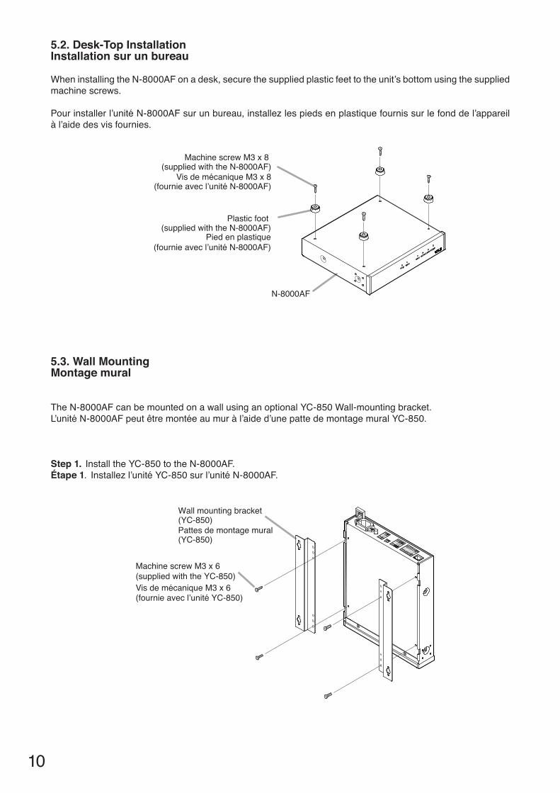
5.2. Desk-Top InstallationInstallation sur un bureau
WheninstallingtheN-8000AFonadesk,securethesuppliedplasticfeettotheunit’sbottomusingthesuppliedmachine screws.
Pourinstallerl’unitéN-8000AFsurunbureau,installezlespiedsenplastiquefournissurlefonddel’appareilàl’aidedesvisfournies.
5.3. Wall MountingMontage mural
TheN-8000AFcanbemountedonawallusinganoptionalYC-850Wall-mountingbracket.L’unitéN-8000AFpeutêtremontéeaumuràl’aided’unepattedemontagemuralYC-850.
Step 1. InstalltheYC-850totheN-8000AF. Étape 1. Installezl’unitéYC-850surl’unitéN-8000AF.
Wall mounting bracket (YC-850)
Machine screw M3 x 6(supplied with the YC-850)
Pattes de montage mural(YC-850)
Vis de mécanique M3 x 6(fournie avec l’unité YC-850)
N-8000AF
Plastic foot (supplied with the N-8000AF)
Machine screw M3 x 8 (supplied with the N-8000AF)
Vis de mécanique M3 x 8(fournie avec l’unité N-8000AF)
Pied en plastique(fournie avec l’unité N-8000AF)
11
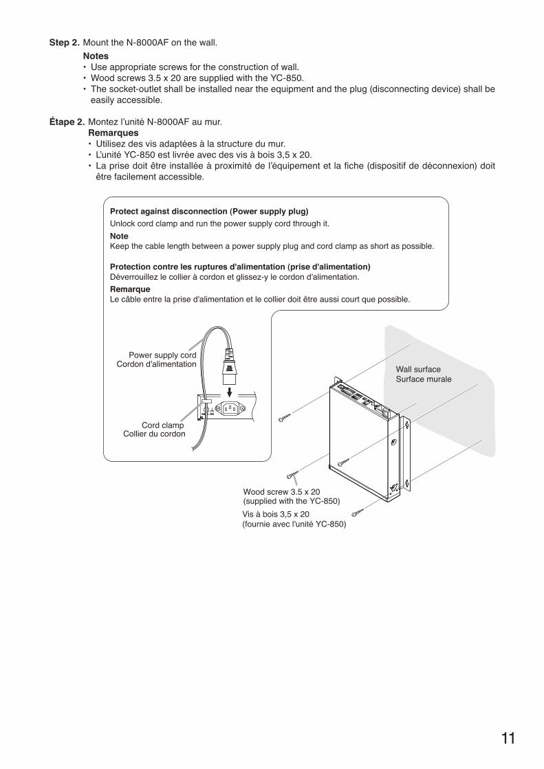
Step 2. MounttheN-8000AFonthewall.Notes• Useappropriatescrewsfortheconstructionofwall.• Woodscrews3.5x20aresuppliedwiththeYC-850.• Thesocket-outletshallbeinstalledneartheequipmentandtheplug(disconnectingdevice)shallbe
easily accessible.
Étape 2. Montezl’unitéN-8000AFaumur.Remarques • Utilisezdesvisadaptéesàlastructuredumur.• L’unitéYC-850estlivréeavecdesvisàbois3,5x20.• Laprisedoitêtreinstalléeàproximitédel’équipementetlafiche(dispositifdedéconnexion)doitêtrefacilementaccessible.
Cord clamp
Power supply cord
Protect against disconnection (Power supply plug)Unlock cord clamp and run the power supply cord through it.NoteKeep the cable length between a power supply plug and cord clamp as short as possible.
Protection contre les ruptures d'alimentation (prise d'alimentation)Déverrouillez le collier à cordon et glissez-y le cordon d'alimentation.RemarqueLe câble entre la prise d'alimentation et le collier doit être aussi court que possible.
Collier du cordon
Cordon d'alimentation
Wood screw 3.5 x 20 (supplied with the YC-850)Vis à bois 3,5 x 20 (fournie avec l'unité YC-850)
Surface muraleWall surface

12
6. WIRING6.1. Connection Diagram
[General description of connection]For cables, refer to p. 14.
1. Power supply connectionConnect the supplied power supply cord to AC Mains or a UPS (Uninterruptible power supply).
About power supply cord handlingThe supplied power supply cord is designed for exclusiveusewiththeN-8000AF.Use the supplied power supply cord only with the N-8000AF.
2. Audio output terminal connectionConnectthemixer,poweramplifier,etc.tothisterminal using the two-core shielded cable.[Audio output terminal specifications]0dB*6,600Ω,balanced.This terminal outputs line level audio signal. H: Hot C: Cold E: Earth
*60dB=1V
1 2 3 4
*2
*4 *5
*3 Be sure to ground.
To AC mains or a UPS (Uninterruptible power supply system)*1
NoteIf there is a danger of lightning strikes, insert an appropriate surge arrester into the power line.
To mixer, power amplifier, etc.
To microphone, audio device, etc.
To network
RJ-45connector
N-8000AFConnected Unit
Hot (H)Cold (C)Earth (E)
Make connections as follows when the connecteddevice has unbalanced inputs.
N-8000AF Audio interface unit
Contact inputsignals
Contact inputsignals
Contact outputsignals
Contact outputsignals
5
5
6
6
7
*2 3P removable terminal plug (supplied with the N-8000AF)*3 2P removable terminal plug (supplied with the N-8000AF)*4 5P removable terminal plug (supplied with the N-8000AF)*5 8P removable terminal plug (supplied with the N-8000AF)
To program timer, etc.
*1 Select an appropriate UPS taking into consideration the total power consumption of all system components and the required back up time, and also the requirement that the UPS should employ the on-line power system.

13
ReferenceAudio interface unit: 7 W (rated) for CE version, 7 W (rated) for CU version8-Port10M/100MSwitchingHub:10W(Differsdependingonproducts.)
NotePlease keep the terminal plug of the attachment not used importantly in preparation for increasing the system.
3. Audio input terminal connectionConnect the microphone, audio device, etc. to this terminal using the two-core shielded cable. [Audio input terminal specifications]–58to0dB*,2kΩ,balanced.This terminal inputs microphone level or line level audio signals.Use software to switch signal levels between microphone and line. H: Hot C: Cold E: Earth
4. Time sync input terminal connectionsConnect the program timer, etc. to this terminal.(Refer to p. 14, "Removable terminal plug connection.")[Specification of no-voltage make contact input]Short-circuit current: 5 mAOpen-circuitvoltage: 24V
5. Contact input terminal connection(Refer to p. 14, "Removable terminal plug connection.")[Specification of no-voltage make contact input]Short-circuit current: 5 mAOpen-circuitvoltage: 24V
6. Contact output terminal connectionContact output terminals have no polarity. (Refer to p. 14, "Removable terminal plug connection.")[Specification of relay contact output]Withstandvoltage: 24VDCControlcurrent: 2mA–500mA
7. Network connectionCan be connected to a network of 10BASE-T/100BASE-TXinauto-sensing.Use a straight through cable of UTP category 5 or more for this connection.
*0dB=1V

14
6.3. Removable terminal plug connection
Step 1. Stripacablejacketofapprox.7mmtoexposeinnercable.
Step 2. Loosen the terminal screws and insert the cables.
Step 3. Tighten the terminal screws securely.Notes• Tuglightlyonthecabletobesurethatitdoesnotpullfree.Ifthecablepullsfree,loosentheterminal
screw again and reconnect from Step 2. • Usethescrewdriverappropriatetothescrewstightenedintotheterminalplug.
7 mm For cables, refer to "Type of Cable" above.
NoteDonotsolderplateonexposedinnercableswhenusingastrandedwire.
6.2. Type of Cable
The types of cables are to be determined according to the following conditions.
• UTPcategory5StraightthroughcableswithRJ45connectoraretobeusedforconnectingtoIPnetwork.• Thenumberofcablespairslaidshouldbedeterminedconsideringthepossibilityoffutureexpansionofthe
system.• Outdoorwiresshouldbeusedwherewiringpassesthrough inaccessibleareassuchasceilingsorunderfloorswherethemaintenanceisnotperformed.Indoorwiresmayalsobeused,however,incasewherethereisnoriskofdeteriorationduetoexposuretoheat,etc.
NoteSpecifications related to junction are as follows.
Removableterminalplug(N-8000AFControlI/OandAudioI/OandTimesyncinputterminal)Conductordiameter: ø0.5–2mm(AWG12–24),Solidwire/Strandedwire
Step 4. InsertthewiredterminalplugintotheterminalblockoftheN-8000AF.
Removable terminal block
Removable terminal plug (accessory)
Tighten
N-8000AF rear panel
2
34

15
7. ACCESSORIES
* Contains theN-8000 setting softwareprogramand theN-8000 series instructionmanual.TheSetupLauncher is automatically started when the supplied CD-ROM is inserted into the PC's drive.NoteIf your PC's CD drive is not compatible with the AutoRun function, the setup guide is not automatically startedevenwhentheCDisinserted.Useeither"Explorer"or"MyComputer"toexecutethefollowingfiles,or use [Start Run]intheTaskBarandenterthefollowingcommand.<DrivewhereCDisplaced>\index.htmlForexample,whenplacingtheCDinthe"d"drive, d:\index.html
8. OPTIONAL PRODUCTS
AC power cord (2 m) .............................................. 1CD* (for PC setting, maintenance use) ................. 1Removable terminal plug (2 pins) .......................... 1Removable terminal plug (3 pins) .......................... 2
Removable terminal plug (5 pins) .......................... 2Removable terminal plug (8 pins) .......................... 2Plastic foot ............................................................. 4MachinescrewM3x8........................................... 4
Rackmountingbracket: MB-15B-BK(forrackmountingoneN-8000AFunit) MB-15B-J(forrackmountingtwoN-8000AFunits)Wallmountingbracket: YC-850

Traceability Information for EuropeManufacturer:
TOA Corporation7-2-1,Minatojima-Nakamachi,Chuo-ku,Kobe,Hyogo,Japan
Authorized representative:TOA Electronics Europe GmbHSuederstrasse 282, 20537 Hamburg,Germany
URL:http://www.toa.jp/133-06-00006-00
• DownloadourTOAProductsData,website(http://www.toa-products.com/international/) togettheup-to-dateversionforN-8000software,firmware,andInstructionmanuals.
• ThesoftwareversionnumbercanbeconfirmedusingtheHelpmenu.• ThecurrentfirmwareversioncanbeconfirmedonthesystemmanagementscreendisplayedwhenthebrowserestablishestheconnectiontotheExchange.
• Theinstructionmanualversionnumbercanbeconfirmedbycheckingthepreparationdate(monthand year) shown at the lower right corner of the last page.
Example:PreparedinNovember2004:200411
Version update information