Armature en barre en fibre de verre pour voussoirs de ... · Enrico Maria Pizzarotti, Pro Iter...
9
- 1 - Armature en barre en fibre de verre pour voussoirs de revêtement des tunnels mécanisés GFRP reinforcement for segmental linings of mechanized excavations Alberto Meda, Université de Rome Tor Vergata, Rome, Italie Matteo Moja, Pro Iter S.r.l., Milan, Italie Enrico Maria Pizzarotti, Pro Iter S.r.l., Milan, Italie Giuseppe Vago, ATP Compositi S.r.l., Angri, Italie Résumé Dans le domaine des tunnels forés par des TBM à bouclier avec revêtements en anneaux de voussoirs préfabriqués, l’utilisation d’armatures en Fibres de Verre en substitution ou intégration de l’armature traditionnelle en barres d’acier est de plus en plus commune. La substitution complète de l’armature en acier par l’armature en Fibres de Verre est utilisée en particulier pour les voussoirs qui doivent être démolis successivement à la phase de mise en œuvre du revêtement, par exemple pour la réalisation de intertubes ou de niches. Dans cet optique, un dimensionnement de l’armature en Fibres de Verre et les résultats d’essais de laboratoire sont illustrés. Les cages d’armatures en Fibres de Verre positionnées en correspondance des coins des voussoirs peuvent jouer un rôle important pour limiter la création de fissurations et de cassures locales causées par des heurts et des conditions de charge anormales, surtout au cours des phases précédent la complète mise en service. Des analyses de laboratoires démontrent l’efficacité de l’armature de renfort en Fibres de Verre dans les coins. Grâce à des analyse sur un modèle 3D qui permettent de considérer la contribution de ces renforts du revêtement durant les phases dinstallation et en service, dont sont illustrés les résultats, la possibilité d’augmenter la résistance du revêtement en étendant l’armature de renforcement in Fibres de Verre à tout le périmètre des voussoirs est mise en évidence. Cette opportunité demande à être analysée avec attention dans le but d’optimiser le coût total du revêtement, compte-tenu des coûts des déchets et des réparations. Abstract The use of GFRP reinforcement is gradually spreading to replace or to integrate the traditional steel rebar for tunnels excavated with shielded TBMs and lined with a precast segmental lining. The complete replacement of the steel rebar with GFRP is particularly used for segments that have to be demolished after their installation, for example for cross-passages or niches realization. In this regard, some examples of their application and of their dimensioning and the results of laboratory tests are described. GFRP reinforcement cages placed on segments’ edges can play an important role to limit the number of cracks and local breakages caused by impacts and unforeseen load conditions, mainly before and during the lining installation. Some laboratory tests were carried out to show the GFRP reinforcement effectiveness. The analyses’ results on a 3D model, which allowed to consider the contribution of such reinforcements both during the lining erection and the service (described below), show that it is possible to increase the lining strength extending the GFRP reinforcements to the whole segments’ perimeter. This has to be carefully analysed to optimize the lining total cost, considering repairs and waste costs.
Transcript of Armature en barre en fibre de verre pour voussoirs de ... · Enrico Maria Pizzarotti, Pro Iter...
- 1 -
Armature en barre en fibre de verre pour voussoirs de revêtement des tunnels mécanisés
GFRP reinforcement for segmental linings of mechanized excavations
Alberto Meda, Université de Rome Tor Vergata, Rome, Italie
Matteo Moja, Pro Iter S.r.l., Milan, Italie
Enrico Maria Pizzarotti, Pro Iter S.r.l., Milan, Italie
Giuseppe Vago, ATP Compositi S.r.l., Angri, Italie
Résumé
Dans le domaine des tunnels forés par des TBM à bouclier avec revêtements en anneaux de
voussoirs préfabriqués, l’utilisation d’armatures en Fibres de Verre en substitution ou intégration de
l’armature traditionnelle en barres d’acier est de plus en plus commune.
La substitution complète de l’armature en acier par l’armature en Fibres de Verre est utilisée en
particulier pour les voussoirs qui doivent être démolis successivement à la phase de mise en œuvre
du revêtement, par exemple pour la réalisation de intertubes ou de niches. Dans cet optique, un
dimensionnement de l’armature en Fibres de Verre et les résultats d’essais de laboratoire sont
illustrés.
Les cages d’armatures en Fibres de Verre positionnées en correspondance des coins des voussoirs
peuvent jouer un rôle important pour limiter la création de fissurations et de cassures locales causées
par des heurts et des conditions de charge anormales, surtout au cours des phases précédent la
complète mise en service.
Des analyses de laboratoires démontrent l’efficacité de l’armature de renfort en Fibres de Verre dans
les coins. Grâce à des analyse sur un modèle 3D qui permettent de considérer la contribution de ces
renforts du revêtement durant les phases dinstallation et en service, dont sont illustrés les résultats, la
possibilité d’augmenter la résistance du revêtement en étendant l’armature de renforcement in Fibres
de Verre à tout le périmètre des voussoirs est mise en évidence. Cette opportunité demande à être
analysée avec attention dans le but d’optimiser le coût total du revêtement, compte-tenu des coûts
des déchets et des réparations.
Abstract
The use of GFRP reinforcement is gradually spreading to replace or to integrate the traditional steel
rebar for tunnels excavated with shielded TBMs and lined with a precast segmental lining.
The complete replacement of the steel rebar with GFRP is particularly used for segments that have to
be demolished after their installation, for example for cross-passages or niches realization. In this
regard, some examples of their application and of their dimensioning and the results of laboratory
tests are described.
GFRP reinforcement cages placed on segments’ edges can play an important role to limit the number
of cracks and local breakages caused by impacts and unforeseen load conditions, mainly before and
during the lining installation.
Some laboratory tests were carried out to show the GFRP reinforcement effectiveness. The analyses’
results on a 3D model, which allowed to consider the contribution of such reinforcements both during
the lining erection and the service (described below), show that it is possible to increase the lining
strength extending the GFRP reinforcements to the whole segments’ perimeter. This has to be
carefully analysed to optimize the lining total cost, considering repairs and waste costs.
- 2 -
Armature en barre en fibre de verre pour voussoirs de revêtement des tunnels mécanisés
GFRP reinforcement for segmental linings of mechanized excavations
Alberto Meda, University of Rome Tor Vergata, Rome, Italy
Matteo Moja, Pro Iter S.r.l., Milan, Italy
Enrico Maria Pizzarotti, Pro Iter S.r.l., Milan, Italy
Giuseppe Vago, ATP Compositi S.r.l., Angri, Italy
1 Introduction
Using the GFRP rebar instead of the traditional steel one for precast segmental lining of TBM tunnels
could be worth in the following cases:
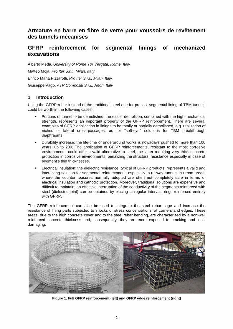
Portions of tunnel to be demolished: the easier demolition, combined with the high mechanical
strength, represents an important property of the GFRP reinforcement. There are several
examples of GFRP application in linings to be totally or partially demolished, e.g. realization of
niches or lateral cross-passages, as for "soft-eye" solutions for TBM breakthrough
diaphragms.
Durability increase: the life-time of underground works is nowadays pushed to more than 100
years, up to 200. The application of GFRP reinforcements, resistant to the most corrosive
environments, could offer a valid alternative to steel, the latter requiring very thick concrete
protection in corrosive environments, penalizing the structural resistance especially in case of
segment’s thin thicknesses.
Electrical insulation: the dielectric resistance, typical of GFRP products, represents a valid and
interesting solution for segmental reinforcement, especially in railway tunnels in urban areas,
where the countermeasures normally adopted are often not completely safe in terms of
electrical insulation and cathodic protection. Moreover, traditional solutions are expensive and
difficult to maintain; an effective interruption of the conductivity of the segments reinforced with
steel (dielectric joint) can be obtained by placing at regular intervals rings reinforced entirely
with GFRP.
The GFRP reinforcement can also be used to integrate the steel rebar cage and increase the
resistance of lining parts subjected to shocks or stress concentrations, at corners and edges. These
areas, due to the high concrete cover and to the steel rebar bending, are characterized by a non-well
reinforced concrete thickness and, consequently, they are more exposed to cracking and local
damaging.
Figure 1. Full GFRP reinforcement (left) and GFRP edge reinforcement (right)
- 3 -
2 Design of GFRP reinforcements replacing the ordinary steel cage
The design of GFRP reinforced segments can be carried out by means of bending moment - axial
force envelopes (M-N). The actions due to transient load conditions (demoulding, storage, transport,
etc.) and final condition (ground pressure) are compared with M-N envelopes defined for the different
stages. Furthermore, the TBM thrust loading condition can be analysed considering the tensile force in
the bars according to the models available in the literature.
For M-N envelopes definition, different guidelines can be followed (ACI 2006, CNR-DT 203 2007, Fib
Bulletin 40, 2007). In the following the method suggested in CNR-DT 203 (Italian Guidelines) is
proposed.
Regarding the concrete behaviour, the design is the same as ordinary steel reinforced concrete while
the GFRP rebar behaviour differs significantly from the steel one. The GFRP rebar shows a linear-
elastic behaviour up to failure. Limits in terms of both strength and deformation are imposed:
ff Ef (1)
f
fkf
f lafd (2)
f
fkafd
9.0 (3)
where ffd e εfd are the design strength and ultimate deformation respectively; Ef is the average Young’s
modulus; ηa, ηl e γf are the environmental reduction factors (ηa=0.7 for wet environment and ηa=0.8 for
dry environment), the long-term loading coefficient (ηl=1 for provisional structures) and the partial
safety factor for GFRP (γf = 1.5). Furthermore, no resistance of GFRP rebar in compression is
considered.
M-N envelopes can be drawn considering the ordinary rules for sectional analyses (sections planarity
and concrete and GFRP rebar relation).
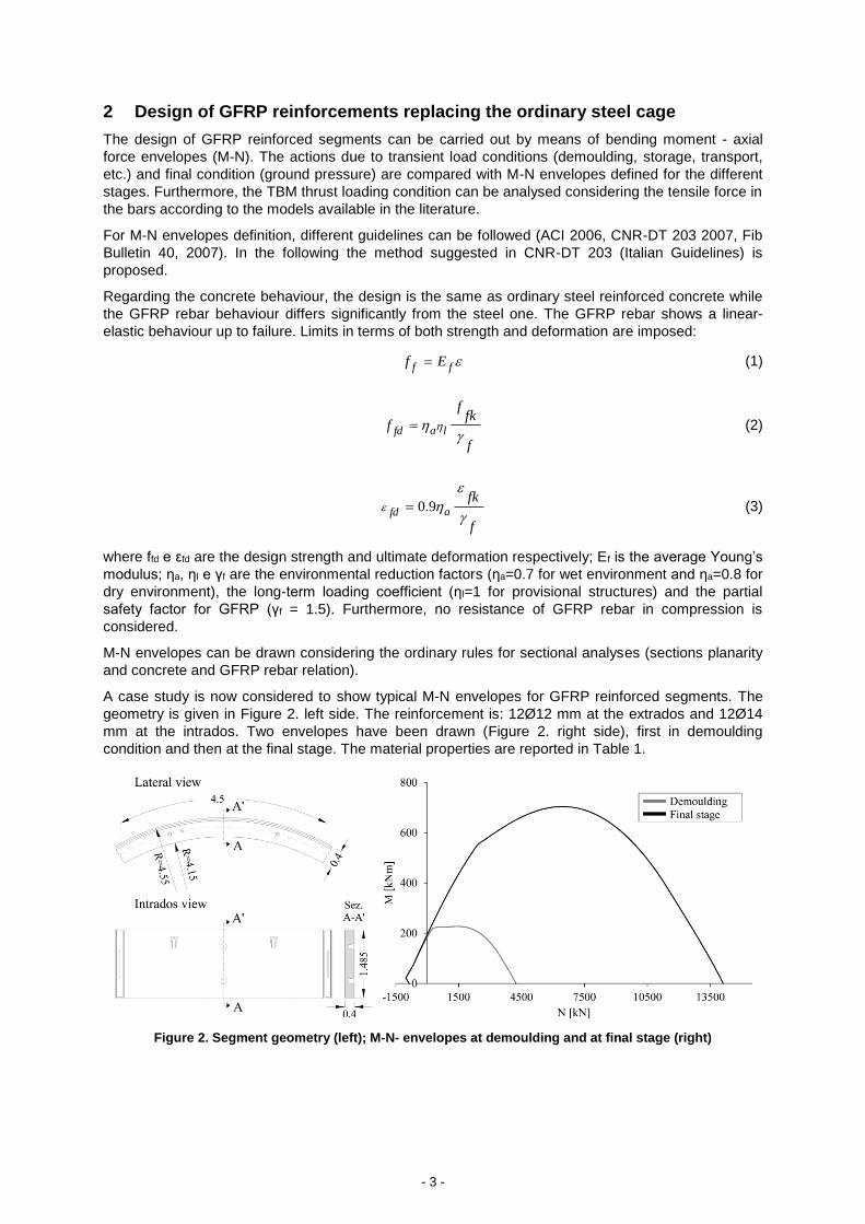
A case study is now considered to show typical M-N envelopes for GFRP reinforced segments. The
geometry is given in Figure 2. left side. The reinforcement is: 12Ø12 mm at the extrados and 12Ø14
mm at the intrados. Two envelopes have been drawn (Figure 2. right side), first in demoulding
condition and then at the final stage. The material properties are reported in Table 1.
Figure 2. Segment geometry (left); M-N- envelopes at demoulding and at final stage (right)
- 4 -
Table 1. Material properties
Concrete cylindrical strength at demoulding fck, 6h 12 MPa
Concrete cylindrical strength final stage fck, 28d 40 MPa
Concrete partial safety coefficient c 1.5
GFRP strength ffk 755 MPa
Young’s modulus Ef 40 GPA
Ultimate deformation fk 0.019
Environmental reduction factor ηa 0.7
Long-term loading coefficient ηl 1
Concrete partial safety coefficient f 1.5
3 Design of GFRP reinforcement integrating the ordinary steel cage
The segments edges can often be subjected to cracking and/or breakages caused by collisions during
transportation, handling and overturning, or by stress concentration during the thrust phase of the
TBM, or even during service.
The concrete compressive stresses and the resulting tensile stresses must be verified.
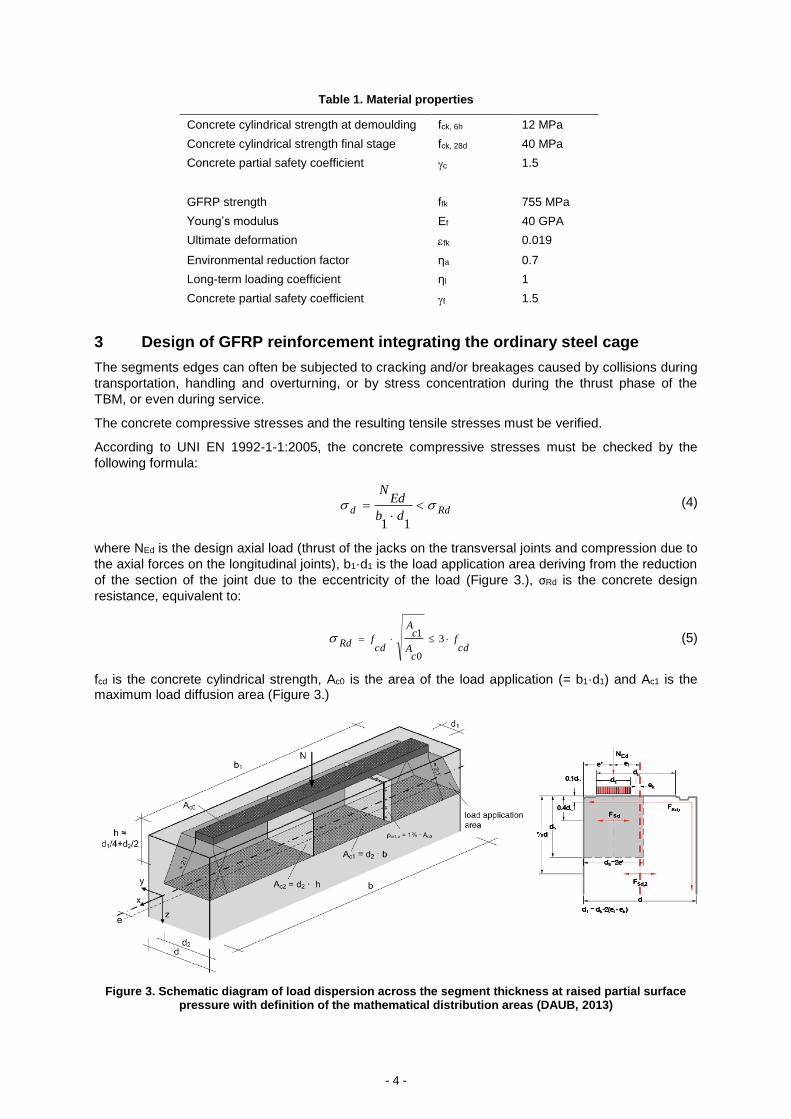
According to UNI EN 1992-1-1:2005, the concrete compressive stresses must be checked by the
following formula:
Rdd
db
EdN
11
(4)
where NEd is the design axial load (thrust of the jacks on the transversal joints and compression due to
the axial forces on the longitudinal joints), b1·d1 is the load application area deriving from the reduction
of the section of the joint due to the eccentricity of the load (Figure 3.), σRd is the concrete design
resistance, equivalent to:
cdf
cA
cA
cdfRd 3
0
1 (5)
fcd is the concrete cylindrical strength, Ac0 is the area of the load application (= b1·d1) and Ac1 is the maximum load diffusion area (Figure 3.)
Figure 3. Schematic diagram of load dispersion across the segment thickness at raised partial surface pressure with definition of the mathematical distribution areas (DAUB, 2013)
- 5 -
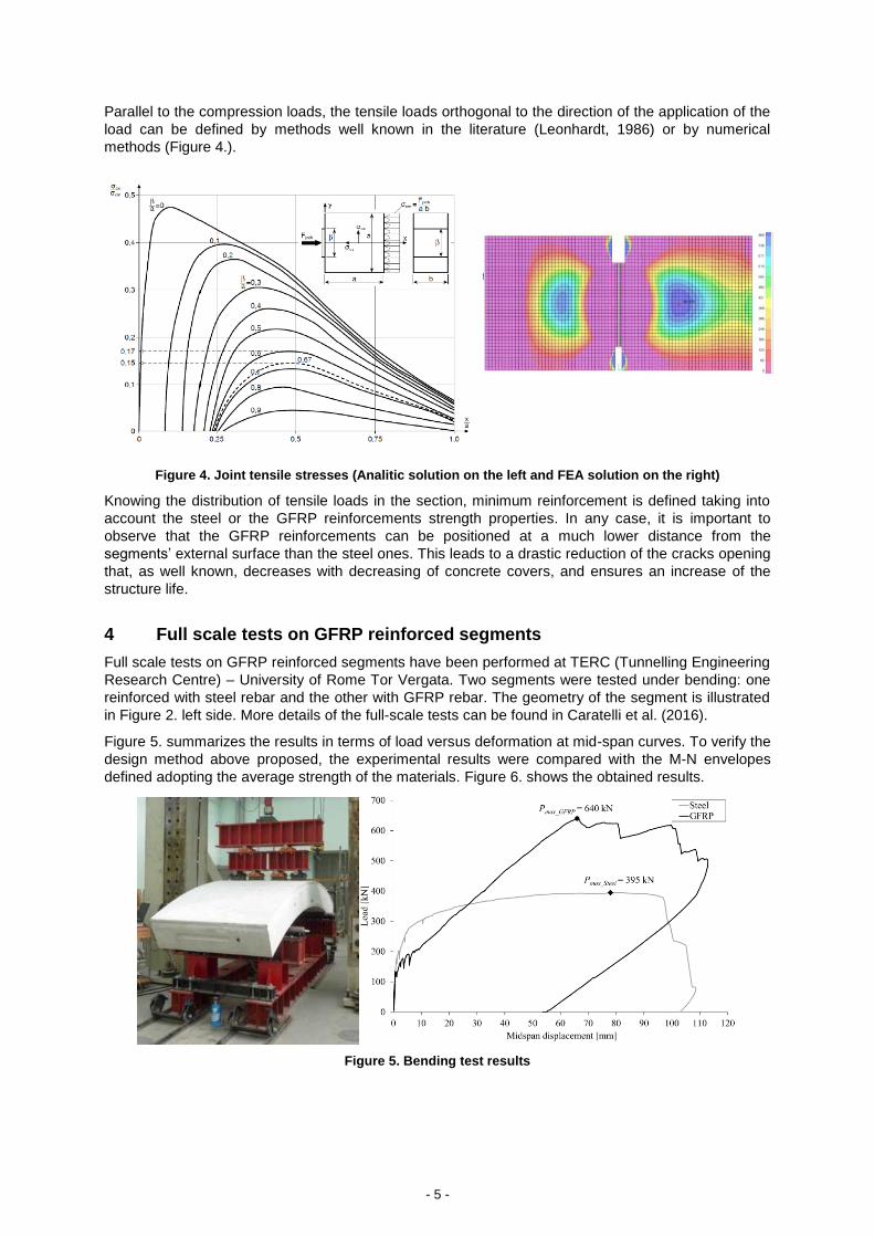
Parallel to the compression loads, the tensile loads orthogonal to the direction of the application of the
load can be defined by methods well known in the literature (Leonhardt, 1986) or by numerical
methods (Figure 4.).
Figure 4. Joint tensile stresses (Analitic solution on the left and FEA solution on the right)
Knowing the distribution of tensile loads in the section, minimum reinforcement is defined taking into
account the steel or the GFRP reinforcements strength properties. In any case, it is important to
observe that the GFRP reinforcements can be positioned at a much lower distance from the
segments’ external surface than the steel ones. This leads to a drastic reduction of the cracks opening
that, as well known, decreases with decreasing of concrete covers, and ensures an increase of the
structure life.
4 Full scale tests on GFRP reinforced segments
Full scale tests on GFRP reinforced segments have been performed at TERC (Tunnelling Engineering
Research Centre) – University of Rome Tor Vergata. Two segments were tested under bending: one
reinforced with steel rebar and the other with GFRP rebar. The geometry of the segment is illustrated
in Figure 2. left side. More details of the full-scale tests can be found in Caratelli et al. (2016).
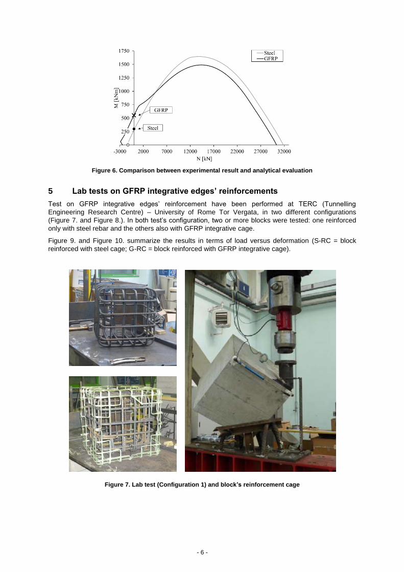
Figure 5. summarizes the results in terms of load versus deformation at mid-span curves. To verify the
design method above proposed, the experimental results were compared with the M-N envelopes
defined adopting the average strength of the materials. Figure 6. shows the obtained results.
Figure 5. Bending test results
- 6 -
Figure 6. Comparison between experimental result and analytical evaluation
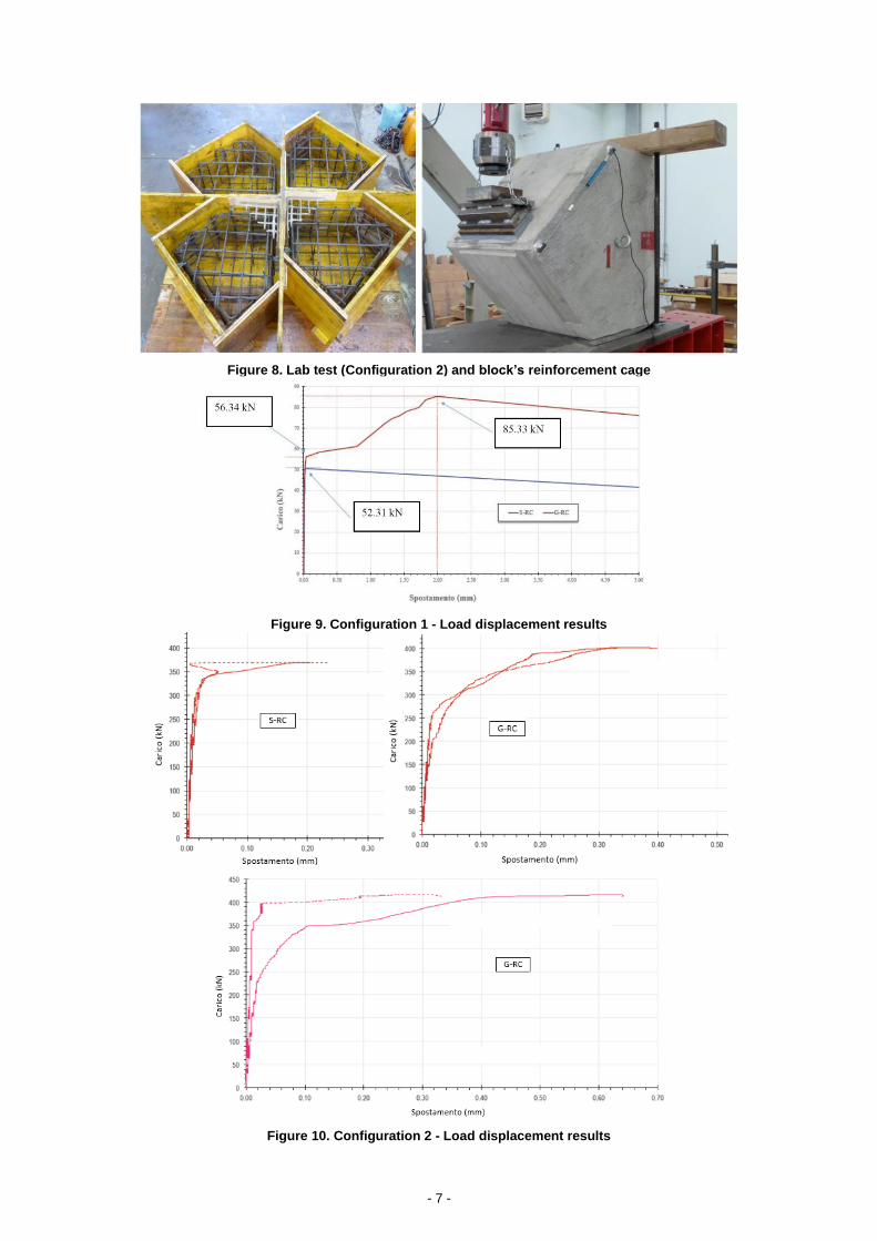
5 Lab tests on GFRP integrative edges’ reinforcements
Test on GFRP integrative edges’ reinforcement have been performed at TERC (Tunnelling
Engineering Research Centre) – University of Rome Tor Vergata, in two different configurations
(Figure 7. and Figure 8.). In both test’s configuration, two or more blocks were tested: one reinforced
only with steel rebar and the others also with GFRP integrative cage.
Figure 9. and Figure 10. summarize the results in terms of load versus deformation (S-RC = block
reinforced with steel cage; G-RC = block reinforced with GFRP integrative cage).
Figure 7. Lab test (Configuration 1) and block’s reinforcement cage
- 7 -
Figure 8. Lab test (Configuration 2) and block’s reinforcement cage
Figure 9. Configuration 1 - Load displacement results
Figure 10. Configuration 2 - Load displacement results
- 8 -
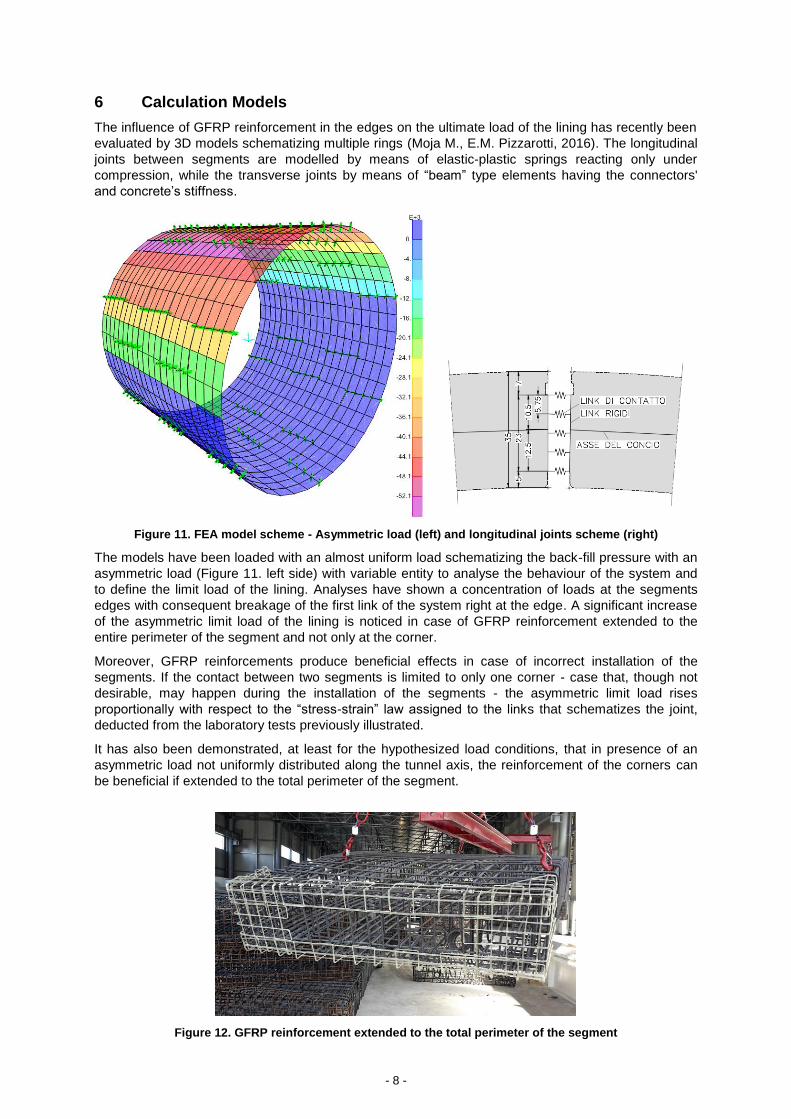
6 Calculation Models
The influence of GFRP reinforcement in the edges on the ultimate load of the lining has recently been
evaluated by 3D models schematizing multiple rings (Moja M., E.M. Pizzarotti, 2016). The longitudinal
joints between segments are modelled by means of elastic-plastic springs reacting only under
compression, while the transverse joints by means of “beam” type elements having the connectors'
and concrete’s stiffness.
Figure 11. FEA model scheme - Asymmetric load (left) and longitudinal joints scheme (right)
The models have been loaded with an almost uniform load schematizing the back-fill pressure with an
asymmetric load (Figure 11. left side) with variable entity to analyse the behaviour of the system and
to define the limit load of the lining. Analyses have shown a concentration of loads at the segments
edges with consequent breakage of the first link of the system right at the edge. A significant increase
of the asymmetric limit load of the lining is noticed in case of GFRP reinforcement extended to the
entire perimeter of the segment and not only at the corner.
Moreover, GFRP reinforcements produce beneficial effects in case of incorrect installation of the
segments. If the contact between two segments is limited to only one corner - case that, though not
desirable, may happen during the installation of the segments - the asymmetric limit load rises
proportionally with respect to the “stress-strain” law assigned to the links that schematizes the joint,
deducted from the laboratory tests previously illustrated.
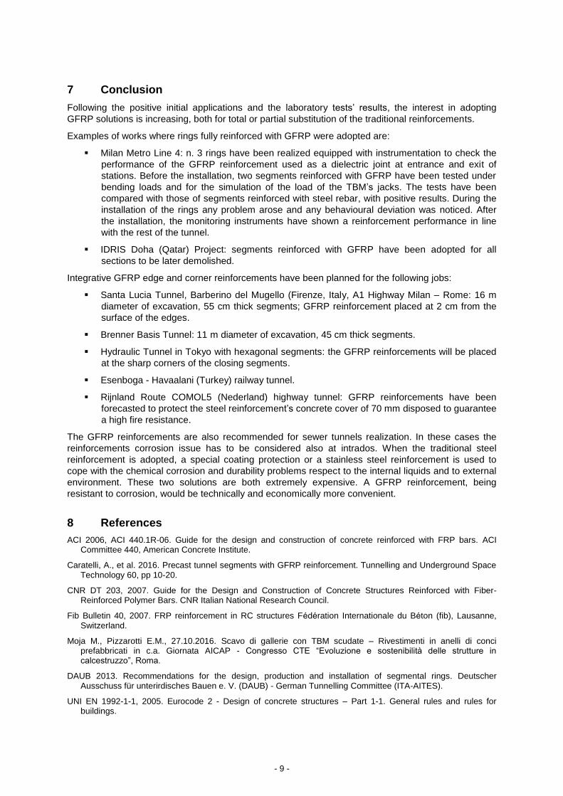
It has also been demonstrated, at least for the hypothesized load conditions, that in presence of an
asymmetric load not uniformly distributed along the tunnel axis, the reinforcement of the corners can
be beneficial if extended to the total perimeter of the segment.
Figure 12. GFRP reinforcement extended to the total perimeter of the segment
- 9 -
7 Conclusion
Following the positive initial applications and the laboratory tests’ results, the interest in adopting
GFRP solutions is increasing, both for total or partial substitution of the traditional reinforcements.
Examples of works where rings fully reinforced with GFRP were adopted are:
Milan Metro Line 4: n. 3 rings have been realized equipped with instrumentation to check the
performance of the GFRP reinforcement used as a dielectric joint at entrance and exit of
stations. Before the installation, two segments reinforced with GFRP have been tested under
bending loads and for the simulation of the load of the TBM’s jacks. The tests have been
compared with those of segments reinforced with steel rebar, with positive results. During the
installation of the rings any problem arose and any behavioural deviation was noticed. After
the installation, the monitoring instruments have shown a reinforcement performance in line
with the rest of the tunnel.
IDRIS Doha (Qatar) Project: segments reinforced with GFRP have been adopted for all
sections to be later demolished.
Integrative GFRP edge and corner reinforcements have been planned for the following jobs:
Santa Lucia Tunnel, Barberino del Mugello (Firenze, Italy, A1 Highway Milan – Rome: 16 m
diameter of excavation, 55 cm thick segments; GFRP reinforcement placed at 2 cm from the
surface of the edges.
Brenner Basis Tunnel: 11 m diameter of excavation, 45 cm thick segments.
Hydraulic Tunnel in Tokyo with hexagonal segments: the GFRP reinforcements will be placed
at the sharp corners of the closing segments.
Esenboga - Havaalani (Turkey) railway tunnel.
Rijnland Route COMOL5 (Nederland) highway tunnel: GFRP reinforcements have been
forecasted to protect the steel reinforcement’s concrete cover of 70 mm disposed to guarantee
a high fire resistance.
The GFRP reinforcements are also recommended for sewer tunnels realization. In these cases the
reinforcements corrosion issue has to be considered also at intrados. When the traditional steel
reinforcement is adopted, a special coating protection or a stainless steel reinforcement is used to
cope with the chemical corrosion and durability problems respect to the internal liquids and to external
environment. These two solutions are both extremely expensive. A GFRP reinforcement, being
resistant to corrosion, would be technically and economically more convenient.
8 References
ACI 2006, ACI 440.1R-06. Guide for the design and construction of concrete reinforced with FRP bars. ACI Committee 440, American Concrete Institute.
Caratelli, A., et al. 2016. Precast tunnel segments with GFRP reinforcement. Tunnelling and Underground Space Technology 60, pp 10-20.
CNR DT 203, 2007. Guide for the Design and Construction of Concrete Structures Reinforced with Fiber-Reinforced Polymer Bars. CNR Italian National Research Council.
Fib Bulletin 40, 2007. FRP reinforcement in RC structures Fédération Internationale du Béton (fib), Lausanne, Switzerland.
Moja M., Pizzarotti E.M., 27.10.2016. Scavo di gallerie con TBM scudate – Rivestimenti in anelli di conci prefabbricati in c.a. Giornata AICAP - Congresso CTE “Evoluzione e sostenibilità delle strutture in calcestruzzo”, Roma.
DAUB 2013. Recommendations for the design, production and installation of segmental rings. Deutscher Ausschuss für unterirdisches Bauen e. V. (DAUB) - German Tunnelling Committee (ITA-AITES).
UNI EN 1992-1-1, 2005. Eurocode 2 - Design of concrete structures – Part 1-1. General rules and rules for buildings.