![E© :3æ ¥ ìG GcG/G Gn p)EFúFùFÿF¸ GAORA SPORTS ...20 20 º 2 v 5 ¥ 4 ' &k GAORA GAORA SPORTS F÷FÿF¸ GeG{5 #+ 20 20 GEG GHG Fþ 70& GMG2G:G GG F¸ í 4( ¥ G]GnGcG/G2GMG](https://static.fdocuments.fr/doc/165x107/601936029b3e406e5d4e6014/e-3-g-gcgg-gn-peffff-gaora-sports-20-20-2-v-5-4-.jpg)
Anleitung eXLink 4+1(A) - crouse-hinds.de · Gerätestecker* GHG 571 9. ca. 41 g ca. 141 g...
44
GHG 570 7001 P0001 D/E/F (E) Betriebsanleitung Explosionsgeschützte Steckverbindungen 5-polig (4+PE) / 4-polig (3+PE), GHG 57. Operating instructions Explosion-protected plug and socket system 5-pole (4+PE) / 4-pole (3+PE), GHG 57. Mode d’emploi Fiches et prises à 5 pôles (4+PE) / 4 pôles (3+PE), pour atmosphères explosives, GHG 57. "En caso necesario podrá solicitar de su representante COOPER Crouse-Hinds estas instrucciones de servicio en otro idioma de la Union Europea" "Se desiderate la traduzione del manuale operativo in un´altra lingua della Comunit à Europea potete richiederla al vostro rappresentante COOPER Crouse-Hinds" "Indien noodzakelijk kan de vertaling van deze gebruiksinstructie in een andere EU- taal worden opgevraagd bij Uw COOPER Crouse-Hinds - vertegenwoordiging" "Tarvittaessa tämän käyttöohjeen käännös on saatavissa toisella EU:n kielellä Teidän COOPER Crouse-Hinds - edustajaltanne" " Εαν χρειασθει, μεταϕραση Εαν χρειασθει, μεταϕραση Εαν χρειασθει, μεταϕραση Εαν χρειασθει, μεταϕραση Εαν χρειασθει, μεταϕραση των οδηγιων των οδηγιων των οδηγιων των οδηγιων των οδηγιων χρησεως σε αλλη χρησεως σε αλλη χρησεως σε αλλη χρησεως σε αλλη χρησεως σε αλλη γλωσσα της ΕΕ, μπορει να ζητηθει γλωσσα της ΕΕ, μπορει να ζητηθει γλωσσα της ΕΕ, μπορει να ζητηθει γλωσσα της ΕΕ, μπορει να ζητηθει γλωσσα της ΕΕ, μπορει να ζητηθει απο τον Αντιπροσωπο της απο τον Αντιπροσωπο της απο τον Αντιπροσωπο της απο τον Αντιπροσωπο της απο τον Αντιπροσωπο της COOPER Crouse-Hinds" "En översättning av denna montage- och skötselinstruktion till annat EU - språk kan vid behov beställas från Er COOPER Crouse-Hinds- representant" "Se for necessária a tradução destas instruções de operação para outro idioma da União Europeia, pode solicita-la junto do seu representante COOPER Crouse-Hinds" "Montagevejledningen kan oversættes til andre EU-sprog og rekvireres hos Deres COOPER Crouse-Hinds leverandør"
Transcript of Anleitung eXLink 4+1(A) - crouse-hinds.de · Gerätestecker* GHG 571 9. ca. 41 g ca. 141 g...

GHG 570 7001 P0001 D/E/F (E)
BetriebsanleitungExplosionsgeschützte Steckverbindungen5-polig (4+PE) / 4-polig (3+PE), GHG 57.
Operating instructionsExplosion-protected plug and socket system5-pole (4+PE) / 4-pole (3+PE), GHG 57.
Mode d’emploiFiches et prises à 5 pôles (4+PE) / 4 pôles(3+PE), pour atmosphères explosives, GHG 57.
"En caso necesario podrá solicitar de surepresentante COOPER Crouse-Hinds estasinstrucciones de servicio en otro idioma de laUnion Europea"
"Se desiderate la traduzione del manualeoperativo in un´altra lingua della Comunit àEuropea potete richiederla al vostrorappresentante COOPER Crouse-Hinds"
"Indien noodzakelijk kan de vertaling vandeze gebruiksinstructie in een andere EU-taal worden opgevraagd bij Uw COOPERCrouse-Hinds - vertegenwoordiging"
"Tarvittaessa tämän käyttöohjeen käännös onsaatavissa toisella EU:n kielellä TeidänCOOPER Crouse-Hinds - edustajaltanne"
""""" Ε α ν χ ρ ε ι α σ θ ε ι , μ ε τ α ϕ ρ α σ ηΕ α ν χ ρ ε ι α σ θ ε ι , μ ε τ α ϕ ρ α σ ηΕ α ν χ ρ ε ι α σ θ ε ι , μ ε τ α ϕ ρ α σ ηΕ α ν χ ρ ε ι α σ θ ε ι , μ ε τ α ϕ ρ α σ ηΕ α ν χ ρ ε ι α σ θ ε ι , μ ε τ α ϕ ρ α σ ητ ω ν ο δ η γ ι ω ντ ω ν ο δ η γ ι ω ντ ω ν ο δ η γ ι ω ντ ω ν ο δ η γ ι ω ντ ω ν ο δ η γ ι ω ν χ ρ η σ ε ω ς σ ε α λ λ ηχ ρ η σ ε ω ς σ ε α λ λ ηχ ρ η σ ε ω ς σ ε α λ λ ηχ ρ η σ ε ω ς σ ε α λ λ ηχ ρ η σ ε ω ς σ ε α λ λ ηγ λ ω σ σ α τ η ς Ε Ε , μ π ο ρ ε ι ν α ζ η τ η θ ε ιγ λ ω σ σ α τ η ς Ε Ε , μ π ο ρ ε ι ν α ζ η τ η θ ε ιγ λ ω σ σ α τ η ς Ε Ε , μ π ο ρ ε ι ν α ζ η τ η θ ε ιγ λ ω σ σ α τ η ς Ε Ε , μ π ο ρ ε ι ν α ζ η τ η θ ε ιγ λ ω σ σ α τ η ς Ε Ε , μ π ο ρ ε ι ν α ζ η τ η θ ε ια π ο τ ο ν Α ν τ ι π ρ ο σ ω π ο τ η ςα π ο τ ο ν Α ν τ ι π ρ ο σ ω π ο τ η ςα π ο τ ο ν Α ν τ ι π ρ ο σ ω π ο τ η ςα π ο τ ο ν Α ν τ ι π ρ ο σ ω π ο τ η ςα π ο τ ο ν Α ν τ ι π ρ ο σ ω π ο τ η ς COOPERCrouse-Hinds"
"En översättning av denna montage- ochskötselinstruktion till annat EU - språk kanvid behov beställas från Er COOPERCrouse-Hinds- representant"
"Se for necessária a tradução destasinstruções de operação para outro idioma daUnião Europeia, pode solicita-la junto do seurepresentante COOPER Crouse-Hinds"
"Montagevejledningen kan oversættes tilandre EU-sprog og rekvireres hos DeresCOOPER Crouse-Hinds leverandør"

2 Cooper Crouse-Hinds GmbH
QUICKON®Geschütztes Warenzeichen derFa."Phönix"Trademark manufakturer "Phönix"La marque protégée de fabrique "Phönix"
Um den Code (Uhrzeit) derKupplung / des Steckersfestzustellen, die Führungs-nase / Nut nach unten (6h)drehen. Alle weiterenCodes resultieren ausdieser Lage.
To climp the code (timecode) fo the coupler /plug the leader nut is turned down. All othercodes are results of this position.
Spannung Polzahl Code Kupplung / Flanschsteckdose Stecker / GerätesteckerVoltage No.of pol. Code Coupler / Flange socket Plug / InletTension Nombre Code Prolongateur / Prise à bride Fiche / socle connecteur
de pôles
Ethernet 4 1 h
Bus 4 2 h
110-130V AC 2 + PE 4 h
24V DC 4 + PE 5 h
230-250V AC 2 + PE 6 h
24V DC 4 8 h
230-250V AC 4 + PE* 10 h
24V AC 2 + PE 12 h
* mit PE-Bügel / with PE clamp / avec étrier PE
2 1
Kodierung der Steckverbindung / Coding of connections /Codification des connexions mâles-femelles
VorgeschlagenerFarbring Code /suggestet rubbercolour code /
1 (L1) PE
2 3 (N)
PE 1 (L1)
3 (N) 2 gelbyellow
grüngreen
2 1
4 3
1 2
1 (L1) PE
2 3 (N)
4 (-) 3
1 2 (+)
3 2
4 1
PE 1 (L1)
3 (N) 2
3 4 (-)
2 (+) 1
2 3
1 4
1 2
PE 3
2 1
3 PE
PE
rotred
graugrey
blaublue
ohne Ringwithout ring
PE
2 (+) 3 2
4 1 PE PE
1 (-)
3 (-)
4 (+)
grün / rotgreen / red
3 4
3 4 4 3
1 2
3Cooper Crouse-Hinds GmbH
Inhalt:Inhalt................................... 3Maßbild............................... 4-5
1 Technische Angaben.......... 32 Sicherheitshinweise............ 53 Normenkonformität............. 54 Verwendungsbereich........... 55 Verwendung/
Eigenschaften..................... 56 Installation........................... 66.1 Montage.............................. 66.2 Öffnen des Gerätes/
Elektrischer Anschluss.... 76.2.1 Crimpanschluss................ 76.2.1.1 Stecker................................ 76.2.1.2 Kupplung............................. 86.2.1.3 Gerätestecker..................... 96.2.1.4 Flanschsteckdose.............. 106.2.2 QUICKON® Anschluss...... 116.2.2.1 Stecker................................ 116.2.2.2 Kupplung............................. 126.2.3 Käfigzugfederanschluss.... 136.2.3.1 Stecker................................ 136.2.3.2 Kupplung............................. 146.2.4 Direktanschluss................ 156.2.4.1 Gerätestecker (Metall)........ 156.2.4.2 Flanschsteckdose (Metall).. 156.3 Kabel- und
Leitungseinführung.............. 156.4 Schließen des Gerätes........ 156.5 Inbetriebnahme................... 157 Instandhaltung/Wartung..... 168 Reparatur / Instandsetzung/
Änderungen........................ 169 Entsorgung / Wieder-
verwertung.......................... 16
Konformitätserklärungseparat beigelegt
Contents:Contents................................ 3Dimensions drawing.............. 17
1 Technical data........................ 2+172 Safety instructions................. 183 Conformity with standards..... 184 Field of application................. 185 Application/Properties........... 186 Installation.............................. 196.1 Mounting................................ 196.2 Opening apparatus /
Electrical connection........... 206.2.1 Crimp connection................. 206.2.1.1 Plug........................................ 206.2.1.2 Coupler.................................. 216.2.1.3 Inlet........................................ 226.2.1.4 Flange socket........................ 236.2.2 QUICKON® connection....... 246.2.2.1 Plug....................................... 246.2.2.2 Coupler.................................. 256.2.3 Spring cage terminal........... 266.2.3.1 Plug........................................ 266.2.3.2 Coupler.................................. 276.2.4 Direkt connect..................... 286.2.4.1 Inlet (metal)............................ 286.2.4.2 Flange socket (metal)............ 286.3 Cable entries........................ 286.4 Closing the device................ 286.5 Putting into operation........... 287 Maintenance/Servicing......... 298 Repairs/Modifications.......... 299 Disposal/Recycling.............. 29
Declaration of conformity,enclosed separately.
Contenu:Contenu................................. 3Plans masse.......................... 30
1 Caractéristiques techniques.. 2+302 Consignes de sécurité........... 313 Conformité avec lesnormes... 314 Domaine d’utilisation............. 315 Utilisation/Propriétés............. 316 Installation.............................. 326.1 Montage................................ 326.2 Ouverture de l’appareil/
Raccordement électrique.... 336.2.1 Sertissage crimp................. 336.2.1.1 Fiche...................................... 336.2.1.2 Prolongateur.......................... 346.2.1.3 Socle connecteur................... 356.2.1.4 Prise de courant à bride......... 366.2.2 Connecteur rapide
QUICKON®.......................... 376.2.2.1 Fiche...................................... 376.2.2.2 Prolongateur.......................... 386.2.3 Raccordement du ressort
de traction à cage................ 396.2.3.1 Fiche...................................... 396.2.3.2 Prolongateur.......................... 406.2.4 Raccordement direct........... 416.2.4.1 Socle connecteur (métallique) 416.2.4.2 Prise de courant à bride
(métallique)............................ 416.3 Entrées de câble et löigne...... 416.4 Fermeture de l’appareil......... 416.5 Mise en service...................... 417 Maintien/Entretien.................. 428 Réparation/Remise
en état/Modifications............. 429 Évacuation des déchets/
Recyclage.............................. 42
Déclaration de conformité,jointe séparément.
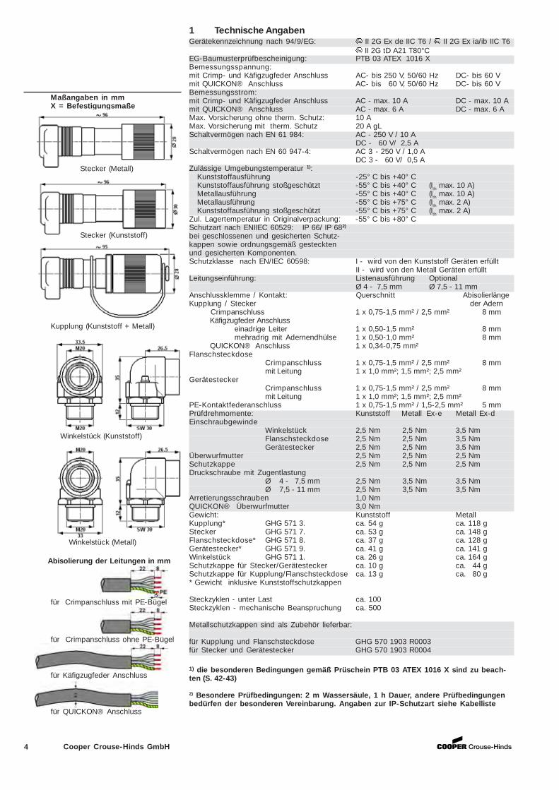
Crimpzangecrimping toolL’aide de la pince
Bestell Nr. / Order No. / Código N°:GHG 570 1902 R0001
Kabelliste cable list Câble liste
Geprüfte Kabeltypen zur Verwendung am Ex-Link Stecksystem IP X8bei 2 m Wassertiefe und eine Stunde untergetaucht.
Kind of cables which can be used with the ex-link connector IP X8protection at 2 m water depht an one hour flooded
Kabeltyp Kabel Schutzartkind of cable cable type of protection
d in mm IPX6 IPX8
Ölflex classic 100 8 xÖlflex classic 400 10 xÖlflex classic 110 5,7 xH07 BQ-F 3G1,5 8,3 xH07 BQ-F 5G1,5 10,5 xJZ-500 9 xy-JZ 7,8 xRD-Y (ST) Y blau 6,3 xJE-LiYCY 6,5 xNYM 3x1,5 9,5 xNYM 5x1,5 10,5 xJE-Y(ST)Y 6,6 xHO7-RN-F 3G1,0 8,8 xHO7-RN-F 3G1,0 10 xHO7-RN-F 3G1,0 11 xHO5-RN-F 3G1,0 6,6 xHO5-RN-F 3G1,0 7 xHO5-RN-F 3G1,0 8,2 xHO5-RN-F 3G1,0 10 xSilflex SiHf 7,8 xLappkabel 2170820 8,0 xLappkabel 2170322 8,0 xLappkabel 2170826 5,1 x
4 Cooper Crouse-Hinds GmbH
1 Technische AngabenGerätekennzeichnung nach 94/9/EG: II 2G Ex de IIC T6 / II 2G Ex ia/ib IIC T6
II 2G tD A21 T80°CEG-Baumusterprüfbescheinigung: PTB 03 ATEX 1016 XBemessungsspannung:mit Crimp- und Käfigzugfeder Anschluss AC- bis 250 V, 50/60 Hz DC- bis 60 Vmit QUICKON® Anschluss AC- bis 60 V, 50/60 Hz DC- bis 60 VBemessungsstrom:mit Crimp- und Käfigzugfeder Anschluss AC - max. 10 A DC - max. 10 Amit QUICKON® Anschluss AC - max. 6 A DC - max. 6 AMax. Vorsicherung ohne therm. Schutz: 10 AMax. Vorsicherung mit therm. Schutz 20 A gLSchaltvermögen nach EN 61 984: AC - 250 V / 10 A
DC - 60 V/ 2,5 ASchaltvermögen nach EN 60 947-4: AC 3 - 250 V / 1,0 A
DC 3 - 60 V/ 0,5 AZulässige Umgebungstemperatur 1):
Kunststoffausführung -25° C bis +40° CKunststoffausführung stoßgeschützt -55° C bis +40° C (Ith max. 10 A)Metallausführung -55° C bis +40° C (Ith max. 10 A)Metallausführung -55° C bis +75° C (Ith max. 2 A)Kunststoffausführung stoßgeschützt -55° C bis +75° C (Ith max. 2 A)
Zul. Lagertemperatur in Originalverpackung: -55° C bis +80° CSchutzart nach ENIIEC 60529: IP 66/ IP 682)
bei geschlossenen und gesicherten Schutz-kappen sowie ordnungsgemäß gestecktenund gesicherten Komponenten.Schutzklasse nach EN/IEC 60598: I - wird von den Kunststoff Geräten erfüllt
II - wird von den Metall Geräten erfülltLeitungseinführung: Listenausführung Optional
Ø 4 - 7,5 mm Ø 7,5 - 11 mmAnschlussklemme / Kontakt: Querschnitt AbisolierlängeKupplung / Stecker der Adern Crimpanschluss 1 x 0,75-1,5 mm² / 2,5 mm² 8 mm Käfigzugfeder Anschluss
einadrige Leiter 1 x 0,50-1,5 mm² 8 mmmehradrig mit Adernendhülse 1 x 0,50-1,0 mm² 8 mm
QUICKON® Anschluss 1 x 0,34-0,75 mm²Flanschsteckdose
Crimpanschluss 1 x 0,75-1,5 mm² / 2,5 mm² 8 mmmit Leitung 1 x 1,0 mm²; 1,5 mm²; 2,5 mm²
GerätesteckerCrimpanschluss 1 x 0,75-1,5 mm² / 2,5 mm² 8 mmmit Leitung 1 x 1,0 mm²; 1,5 mm²; 2,5 mm²
PE-Kontaktfederanschluss 1 x 0,75-1,5 mm² / 1,5-2,5 mm² 5 mmPrüfdrehmomente: Kunststoff Metall Ex-e Metall Ex-dEinschraubgewinde
Winkelstück 2,5 Nm 2,5 Nm 3,5 NmFlanschsteckdose 2,5 Nm 2,5 Nm 3,5 NmGerätestecker 2,5 Nm 2,5 Nm 3,5 Nm
Überwurfmutter 2,5 Nm 2,5 Nm 2,5 NmSchutzkappe 2,5 Nm 2,5 Nm 2,5 NmDruckschraube mit Zugentlastung
Ø 4 - 7,5 mm 2,5 Nm 3,5 Nm 3,5 NmØ 7,5 - 11 mm 2,5 Nm 3,5 Nm 3,5 Nm
Arretierungsschrauben 1,0 NmQUICKON® Überwurfmutter 3,0 NmGewicht: Kunststoff MetallKupplung* GHG 571 3. ca. 54 g ca. 118 gStecker GHG 571 7. ca. 53 g ca. 148 gFlanschsteckdose* GHG 571 8. ca. 37 g ca. 128 gGerätestecker* GHG 571 9. ca. 41 g ca. 141 gWinkelstück GHG 571 1. ca. 26 g ca. 164 gSchutzkappe für Stecker/Gerätestecker ca. 10 g ca. 44 gSchutzkappe für Kupplung/Flanschsteckdose ca. 13 g ca. 80 g* Gewicht inklusive Kunststoffschutzkappen
Steckzyklen - unter Last ca. 100Steckzyklen - mechanische Beanspruchung ca. 500
Metallschutzkappen sind als Zubehör lieferbar:
für Kupplung und Flanschsteckdose GHG 570 1903 R0003für Stecker und Gerätestecker GHG 570 1903 R0004
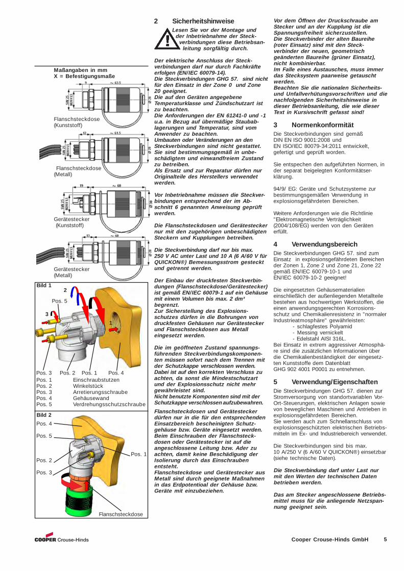
Maßangaben in mmX = Befestigungsmaße
Abisolierung der Leitungen in mm
für Crimpanschluss mit PE-Bügel
für Käfigzugfeder Anschluss
für QUICKON® Anschluss
Kupplung (Kunststoff + Metall)
Stecker (Kunststoff)
Stecker (Metall)
Winkelstück (Kunststoff)
Winkelstück (Metall)
für Crimpanschluss ohne PE-Bügel
1) die besonderen Bedingungen gemäß Prüschein PTB 03 ATEX 1016 X sind zu beach-ten (S. 42-43)
2) Besondere Prüfbedingungen: 2 m Wassersäule, 1 h Dauer, andere Prüfbedingungenbedürfen der besonderen Vereinbarung. Angaben zur IP-Schutzart siehe Kabelliste
5Cooper Crouse-Hinds GmbH
2 SicherheitshinweiseLesen Sie vor der Montage und
der Inbetriebnahme der Steck-verbindungen diese Betriebsan-
leitung sorgfältig durch.
Der elektrische Anschluss der Steck-verbindungen darf nur durch Fachkräfteerfolgen (EN/IEC 60079-14).Die Steckverbindungen GHG 57. sind nichtfür den Einsatz in der Zone 0 und Zone20 geeignet.Die auf den Geräten angegebeneTemperaturklasse und Zündschutzart istzu beachten.Die Anforderungen der EN 61241-0 und -1u.a. in Bezug auf übermäßige Staubab-lagerungen und Temperatur, sind vomAnwender zu beachten.Umbauten oder Veränderungen an denSteckverbindungen sind nicht gestattet.Sie sind bestimmungsgemäß in unbe-schädigtem und einwandfreiem Zustandzu betreiben.Als Ersatz und zur Reparatur dürfen nurOriginalteile des Herstellers verwendetwerden.
Vor Inbetriebnahme müssen die Steckver-bindungen entsprechend der im Ab-schnitt 6 genannten Anweisung geprüftwerden.
Die Flanschsteckdosen und Gerätesteckernur mit den zugehörigen unbeschädigtenSteckern und Kupplungen betreiben.
Die Steckverbindung darf nur bis max.250 V AC unter Last und 10 A (6 A/60 V fürQUICKON®) Bemessungsstrom gestecktund getrennt werden.
Der Einbau der druckfesten Steckverbin-dungen (Flanschsteckdose/Gerätestecker)ist gemäß EN/IEC 60079-1 auf ein Gehäusemit einem Volumen bis max. 2 dm³begrenzt.Zur Sicherstellung des Explosions-schutzes dürfen in die Bohrungen vondruckfesten Gehäusen nur Gerätesteckerund Flanschsteckdosen aus Metalleingesetzt werden.
Die im geöffneten Zustand spannungs-führenden Steckverbindungskomponen-ten müssen sofort nach dem Trennen mitder Schutzkappe verschlossen werden.Dabei ist auf den korrekten Verschluss zuachten, da sonst die Mindestschutzartund der Explosionsschutz nicht mehrgewährleistet sind.Nicht benutzte Komponenten sind mit derSchutzkappe verschlossen aufzubewahren.
Flanschsteckdosen und Gerätesteckerdürfen nur in die für den entsprechendenEinsatzbereich bescheinigten Schutz-gehäuse bzw. Geräte eingesetzt werden.Beim Einschrauben der Flanschsteck-dosen oder Gerätestecker ist auf dieangeschlossene Leitung bzw. Ader zuachten, damit keine Beschädigung derIsolierung durch das Einschraubenentsteht.Flanschsteckdose und Gerätestecker ausMetall sind durch geeignete Maßnahmenin das Erdpotentioal der Gehäuse bzw.Geräte mit einzubeziehen.
Maßangaben in mmX = Befestigungsmaße
3
2
1
Pos. 3 Pos. 2 Pos. 1 Pos. 4 Pos. 1 Einschraubstutzen Pos. 2 Winkelstück Pos. 3 Arretierungsschraube Pos. 4 Gehäusewand Pos. 5 Verdrehungsschutzschraube
Pos. 4
Pos. 5
Pos. 1 Pos. 2
Pos. 3
Flanschsteckdose
Bild 2
Pos. 5
Gerätestecker (Kunststoff)
Gerätestecker(Metall)
Flanschsteckdose(Metall)
Flanschsteckdose(Kunststoff)
Bild 1
Vor dem Öffnen der Druckschraube amStecker und an der Kupplung ist dieSpannungsfreiheit sicherzustellen.Die Steckverbinder der alten Baureihe(roter Einsatz) sind mit den Steck-verbinder der neuen, geometrischgeänderten Baureihe (grüner Einsatz),nicht kombinierbar.Im Falle eines Austausches, muss immerdas Stecksystem paarweise getauschtwerden.Beachten Sie die nationalen Sicherheits-und Unfallverhütungsvorschriften und dienachfolgenden Sicherheitshinweise indieser Betriebsanleitung, die wie dieserText in Kursivschrift gefasst sind!
3 NormenkonformitätDie Steckverbindungen sind gemäßDIN EN ISO 9001:2008 undEN ISO/IEC 80079-34:2011 entwickelt,gefertigt und geprüft worden.
Sie entspechen den aufgeführten Normen, inder separat beigelegten Konformitätser-klärung.
94/9/ EG: Geräte und Schutzsysteme zurbestimmungsgemäßen Verwendung inexplosionsgefährdeten Bereichen.
Weitere Anforderungen wie die Richtlinie"Elektromagnetische Verträglichkeit(2004/108/EG) werden von den Gerätenerfüllt.
4 VerwendungsbereichDie Steckverbindungen GHG 57. sind zumEinsatz in explosionsgefährdeten Bereichender Zonen 1, Zone 2 und Zone 21, Zone 22gemäß EN/IEC 60079-10-1 undEN/IEC 60079-10-2 geeignet!
Die eingesetzten Gehäusematerialieneinschließlich der außenliegenden Metallteilebestehen aus hochwertigen Werkstoffen, dieeinen anwendungsgerechten Korrosions-schutz und Chemikalienresistenz in "normalerIndustrieatmosphäre" gewährleisten:
- schlagfestes Polyamid- Messing vernickelt- Edelstahl AISI 316L.
Bei Einsatz in extrem aggressiver Atmosphä-re sind die zusätzlichen Informationen überdie Chemikalienbeständigkeit der eingesetz-ten Kunststoffe dem DatenblattGHG 902 4001 P0001 zu entnehmen.
5 Verwendung/EigenschaftenDie Steckverbindungen GHG 57. dienen zurStromversorgung von standortvariablen Vor-Ort-Steuerungen, elektrischen Anlagen sowievon beweglichen Maschinen und Antrieben inexplosionsgefährdeten Bereichen.Sie werden auch zum Schnellanschluss vonexplosionsgeschützten elektrischen Betriebs-mitteln im Ex- und Industriebereich verwendet.
Die Steckverbindungen sind bis max.10 A/250 V (6 A/60 V QUICKON®) einsetzbar(siehe technische Daten).
Die Steckverbindung darf unter Last nurmit den Werten der technischen Datenbetrieben werden.
Das am Stecker angeschlossene Betriebs-mittel muss für die anliegende Netzspan-nung geeignet sein.
6 Cooper Crouse-Hinds GmbH
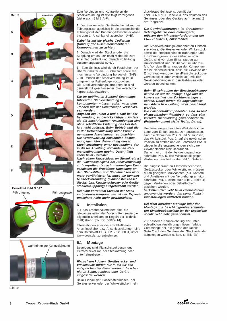
Zum Verbinden und Kontaktieren derSteckverbindung ist wie folgt vorzugehen(siehe auch Bild 3 A-F):
1. Der Stecker oder Gerätestecker ist mit derFührungsnase lagerichtig in die entsprechendeFührungsnut der Kupplung/Flanschsteckdosebis zum 1. Anschlag einzustecken (A+B).
Dabei ist auf die gleiche Codierung(Uhrzeit) der zusammensteckbarenKomponenten zu achten.
2. Danach wird der Stecker oder dieKupplung um ca. 30° nach rechts bis zumAnschlag gedreht und danach vollständigzusammengesteckt (C+D).
3. Zum Schluss wird durch Festdrehen derÜberwurfmutter die IP-Schutzart sowie diemechanische Verbindung hergestellt (E+F).Zum Trennen der Steckverbindung ist inumgekehrter Reihenfolge vorzugehen.Die Steckverbindungskomponenten sindgenerell mit geschlossener Steckerschutz-kappe aufzubewahren.
Die im geöffneten Zustand Spannungs-führenden Steckverbindungs-komponenten müssen sofort nach demTrennen mit der Schutzkappe verschlos-sen werden.Angaben aus Punkt 3 und 4 sind bei derVerwendung zu berücksichtigen. Andereals die beschriebenen Anwendungen sindohne schriftliche Erklärung des Herstel-lers nicht zulässig. Beim Betrieb sind diein der Betriebsanleitung unter Punkt 7genannten Anweisungen zu beachten.Die Verantwortung hinsichtlich bestim-mungsgemäßer Verwendung dieserSteckvorrichtung unter Bezugnahme derin dieser Anleitung vorhandenen Rah-menbedingungen (techn. Daten) liegtallein beim Betreiber.Nach einem Kurzschluss im Stromkreis istdie Funktionsfähigkeit der Steckverbindungzu überprüfen, da nach mehrmaligen Kurz-schlüssen die druckfeste Kapselung anden Steckstiften und Steckbuchsen nichtmehr gewährleistet ist, muss die komplet-te Steckverbindung (Flanschsteckdose/Stecker bzw. Kupplung/Stecker oder Geräte-stecker/Kupplung) ausgetauscht werden.
Bei nicht korrektem Stecken der Steck-verbindungskomponenten ist der Explosi-onsschutz nicht mehr gewährleistet.
6 InstallationFür das Errichten/Betreiben sind dierelevanten nationalen Vorschriften sowie dieallgemein anerkannten Regeln der Technikmaßgebend (EN/IEC 60079-14).
Informationen über die anschließbarenAnschlusskabel bzw Anschlussleitungen sinddem Datenblatt GHG 902 5012 F0001, unterwww.ceag.de, zu entnehmen.
6.1 MontageBevorzugt sind Flanschsteckdosen undGerätestecker mit der Stecköffnung nachunten einzubauen.
Flanschsteckdosen, Gerätestecker undWinkelstück dürfen nur in die für denentsprechenden Einsatzbereich beschei-nigten Schutzgehäuse oder Geräteeingesetzt werden.
Beim Einbau der Flanschsteckdosen, derGerätestecker oder der Winkelstücke in ein
Bild 3 Einzelheit
Führungsnut Führungsnase
A
B
C
D
E
F
Einzelheit Bild 3 "A"
druckfestes Gehäuse ist gemäß derEN/IEC 60079-1, Tabelle 3, das Volumen desGehäuses oder des Gerätes auf maximal 2dm³ begrenzt.
Die Gewindebohrungen im druckfestenSchutzgehäuse oder Einbaugerät,müssen den Mindestanforderungen derEN/IEC 60079-1, entsprechen.
Die Steckverbindungskomponenten Flansch-steckdose, Gerätestecker oder Winkelstücksowie die entsprechenden Bohrungen undEinschraubgewinde der Gehäuse oderGeräte sind vor dem Einschrauben aufUnversehrtheit und Sauberkeit zu überprü-fen. Vor dem Einschrauben der Komponen-ten ist sicherzustellen, dass die Gewinde derEinschraubkomponenten (Flanschsteckdose,Gerätestecker oder Winkelstück) mit denGewindebohrungen in den Gehäusen oderGeräten übereinstimmt.
Beim Einschrauben der Einschraubkompo-nenten ist auf die richtige Lage und dieUnversehrtheit des Dichtungsringes zuachten. Dabei dürfen die angeschlosse-nen Adern bzw Leitung nicht beschädigtwerden.Die Einschraubkomponenten sind so festeinzuschrauben (handfest), so dass einekorrekte Dichtwirkung gewährleistet ist.(Prüfdrehmoment siehe Techn. Daten).
Um beim eingeschraubten Winkelstück dieLage zum Einführungsstutzen anzupassen,sind die Schrauben Pos. 3 und 5, zu lösen,das Winkelstück Pos. 2, auf die gewünschtePosition zu drehen und die Schrauben Pos. 3,wieder in die entsprechenden sichtbarenGewindelöcher einzuschrauben.Danach wird mit der Verdrehungsschutz-schraube Pos. 5, das Winkelstück gegenVerdrehen gesichert (siehe Bild 1, Seite 4).
Die eingeschraubten Flanschsteckdosen,Gerätestecker oder Winkelstücke, müssendurch geeignete Maßnahmen (z.B. Konternund Arretieren mit der Verdrehungsschutz-schraube Pos. 5, siehe auch Bild 2, Seite 4)gegen Verdrehen oder Selbstlockerngesichert werden.Verkleben darf nicht beim Gerätesteckerangewendet werden, das sonst Funkst-ionsstörungen auftreten können.
Bei nicht korrekter Montage oder derMontage mit beschädigten/verschmutz-ten Einschraubgewinde ist der Explosions-schutz nicht mehr gewährleistet.
Zur besseren Kennzeichnung der unter-schiedlichen Ausführungen liegen farbigeGummiringe bei, die gemäß der TabelleSeite 2 auf den Gehäuse der Steckverbinderaufgezogen werden sollten. (s. Bild 3b)
Gummiring zur Kennzeichnung
Bild 3b
7Cooper Crouse-Hinds GmbH
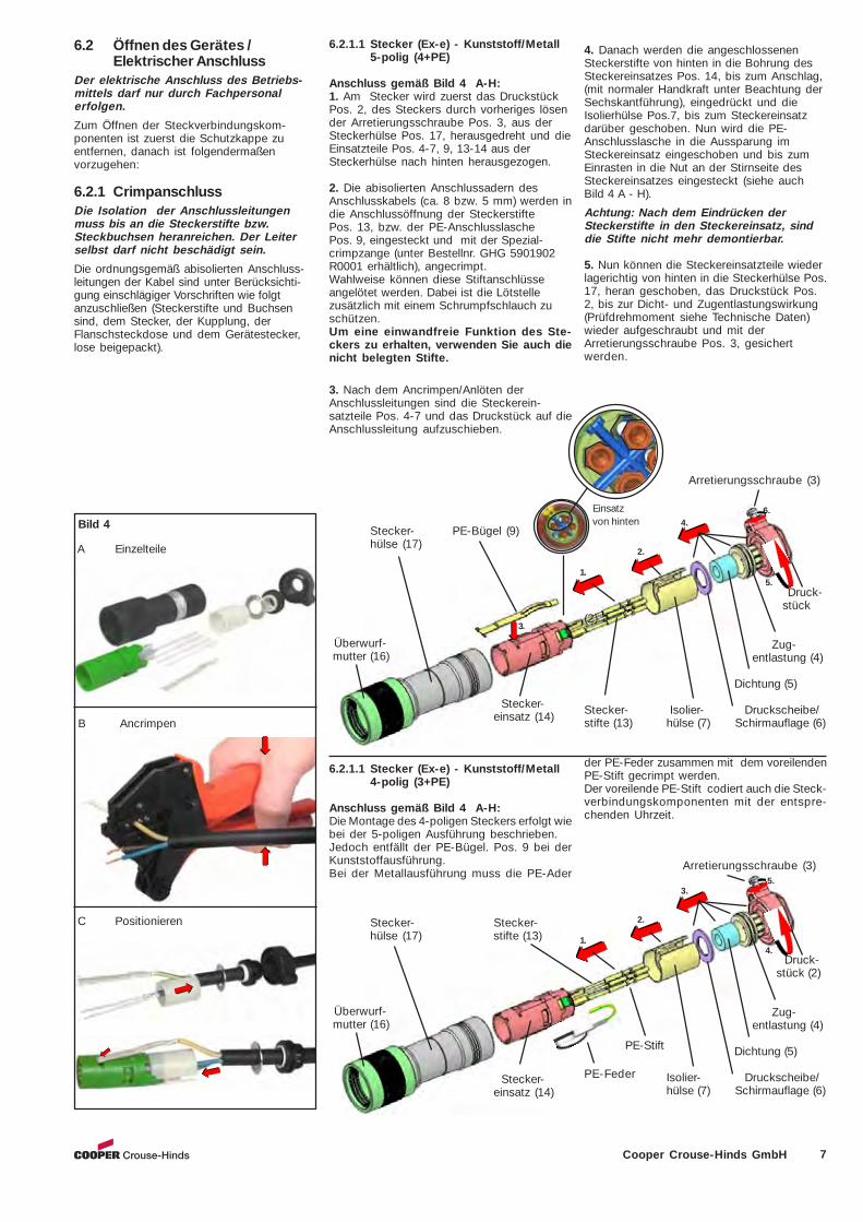
Überwurf- mutter (16)
Stecker- Stecker-hülse (17) stifte (13) 1.
2.
5.
4. Druck-
stück (2)
Zug- entlastung (4)
Dichtung (5)
Isolier- Druckscheibe/hülse (7) Schirmauflage (6)
3.
Stecker-einsatz (14)
PE-Stift
PE-Feder
Überwurf- mutter (16)
6.2 Öffnen des Gerätes /Elektrischer Anschluss
Der elektrische Anschluss des Betriebs-mittels darf nur durch Fachpersonalerfolgen.
Zum Öffnen der Steckverbindungskom-ponenten ist zuerst die Schutzkappe zuentfernen, danach ist folgendermaßenvorzugehen:
6.2.1 CrimpanschlussDie Isolation der Anschlussleitungenmuss bis an die Steckerstifte bzw.Steckbuchsen heranreichen. Der Leiterselbst darf nicht beschädigt sein.
Die ordnungsgemäß abisolierten Anschluss-leitungen der Kabel sind unter Berücksichti-gung einschlägiger Vorschriften wie folgtanzuschließen (Steckerstifte und Buchsensind, dem Stecker, der Kupplung, derFlanschsteckdose und dem Gerätestecker,lose beigepackt).
3.
Stecker- PE-Bügel (9)hülse (17)
1.
2.
6.
5.
Arretierungsschraube (3)
Druck- stück
(2)
Zug- entlastung (4)
Dichtung (5)
Stecker- Isolier- Druckscheibe/stifte (13) hülse (7) Schirmauflage (6)
Stecker-einsatz (14)
Bild 4
A Einzelteile
B Ancrimpen
C Positionieren
4.
6.2.1.1 Stecker (Ex-e) - Kunststoff/Metall4-polig (3+PE)
Anschluss gemäß Bild 4 A-H:Die Montage des 4-poligen Steckers erfolgt wiebei der 5-poligen Ausführung beschrieben.Jedoch entfällt der PE-Bügel. Pos. 9 bei derKunststoffausführung.Bei der Metallausführung muss die PE-Ader
6.2.1.1 Stecker (Ex-e) - Kunststoff/Metall5-polig (4+PE)
Anschluss gemäß Bild 4 A-H:1. Am Stecker wird zuerst das DruckstückPos. 2, des Steckers durch vorheriges lösender Arretierungsschraube Pos. 3, aus derSteckerhülse Pos. 17, herausgedreht und dieEinsatzteile Pos. 4-7, 9, 13-14 aus derSteckerhülse nach hinten herausgezogen.
2. Die abisolierten Anschlussadern desAnschlusskabels (ca. 8 bzw. 5 mm) werden indie Anschlussöffnung der SteckerstiftePos. 13, bzw. der PE-AnschlusslaschePos. 9, eingesteckt und mit der Spezial-crimpzange (unter Bestellnr. GHG 5901902R0001 erhältlich), angecrimpt.Wahlweise können diese Stiftanschlüsseangelötet werden. Dabei ist die Lötstellezusätzlich mit einem Schrumpfschlauch zuschützen.Um eine einwandfreie Funktion des Ste-ckers zu erhalten, verwenden Sie auch dienicht belegten Stifte.
3. Nach dem Ancrimpen/Anlöten derAnschlussleitungen sind die Steckerein-satzteile Pos. 4-7 und das Druckstück auf dieAnschlussleitung aufzuschieben.
4. Danach werden die angeschlossenenSteckerstifte von hinten in die Bohrung desSteckereinsatzes Pos. 14, bis zum Anschlag,(mit normaler Handkraft unter Beachtung derSechskantführung), eingedrückt und dieIsolierhülse Pos.7, bis zum Steckereinsatzdarüber geschoben. Nun wird die PE-Anschlusslasche in die Aussparung imSteckereinsatz eingeschoben und bis zumEinrasten in die Nut an der Stirnseite desSteckereinsatzes eingesteckt (siehe auchBild 4 A - H).
Achtung: Nach dem Eindrücken derSteckerstifte in den Steckereinsatz, sinddie Stifte nicht mehr demontierbar.
5. Nun können die Steckereinsatzteile wiederlagerichtig von hinten in die Steckerhülse Pos.17, heran geschoben, das Druckstück Pos.2, bis zur Dicht- und Zugentlastungswirkung(Prüfdrehmoment siehe Technische Daten)wieder aufgeschraubt und mit derArretierungsschraube Pos. 3, gesichertwerden.
Einsatzvon hinten
der PE-Feder zusammen mit dem voreilendenPE-Stift gecrimpt werden.Der voreilende PE-Stift codiert auch die Steck-verbindungskomponenten mit der entspre-chenden Uhrzeit.
Arretierungsschraube (3)
8 Cooper Crouse-Hinds GmbH
Arretierungs- schraube (3)
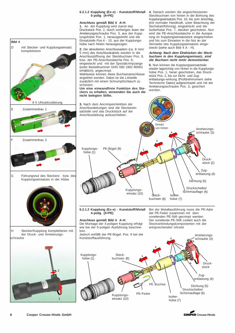
6.2.1.2 Kupplung (Ex-e) - Kunststoff/Metall5-polig (4+PE)
Anschluss gemäß Bild 4 A-H:1. An der Kupplung wird zuerst dasDruckstück Pos. 2, durch vorheriges lösen derArretierungsschraube Pos. 3, aus der Kupp-lungshülse Pos. 1, herausgedreht und dieEinsatzteile Pos.4 - 10, aus der Kupplungs-hülse nach hinten herausgezogen.
2. Die abisolierten Anschlussadern (ca. 8 mm/5 mm) des Anschlusskabels werden in dieAnschlussöffnung der Steckbuchsen Pos. 8,bzw. der PE-Anschlusslasche Pos. 9,eingesteckt und mit der Spezialcrimpzange(unter Bestellnummer GHG 590 1902 R0001erhältlich), angecrimpt.Wahlweise können diese Buchsenanschlüsseangelötet werden. Dabei ist die Lötstellezusätzlich mit einem Schrumpfschlauch zuschützen.Um eine einwandfreie Funktion des Ste-ckers zu erhalten, verwenden Sie auch dienicht belegten Stifte.
3. Nach dem Ancrimpen/Anlöten derAnschlussleitungen sind die Steckerein-satzteile und das Druckstück auf dieAnschlussleitung aufzuschieben.
3.
Kupplungs- PE-Bügel (9) hülse (1)
1.
2.
4.6.
5. Druck- stück (2)
Kupplungs- einsatz (10)
Zug- entlastung (4)
Dichtung (5)
Druckscheibe/Schirmauflage (6)
Steck- Isolier-buchsen (8) hülse (7)
D mit Stecker- und Kupplungseinsatzkomplettieren
E Zusammenbau 1
6.2.1.2 Kupplung (Ex-e) - Kunststoff/Metall4-polig (3+PE)
Anschluss gemäß Bild 4 A-H:Die Montage der 4-poligen Kupplung erfolgtwie bei der 5-poligen Ausführung beschrie-ben.Jedoch entfällt der PE-Bügel. Pos. 9 bei derKunststoffausführung.
Arretierungs- schraube (3)
Kupplungs- Steck- hülse (1) buchsen (8)
1.
2.
3.5.
4. Druck- stück
(2)
Kupplungs-einsatz (10)
Bei der Metallausführung muss die PE-Aderder PE-Feder zusammen mit demvoreilenden PE-Stift gecrimpt werden.Der voreilende PE-Stift codiert auch dieSteckverbindungskomponenten mit derentsprechenden Uhrzeit
Bild 4
F Zusammenbau 2
G Führungsnut des Steckers- bzw. desKupplungseinsatzes in der Hülse
H Stecker/Kupplung komplettieren mitder Druck- und Arretierungs-
schraube
2
1
6 h Uhrzeitcodierung
4. Danach werden die angeschlossenenSteckbuchsen von hinten in die Bohrung desKupplungseinsatzes Pos. 10, bis zum Anschlag,(mit normaler Handkraft, unter Beachtung derSechskantführung), eingedrückt und dieIsolierhülse Pos. 7, darüber geschoben. Nunwird die PE-Anschlusslasche in die Ausspa-rung im Kupplungseinsatzstück eingeschobenund bis zum Einrasten in die Nut an derStirnseite des Kupplungseinsatzes einge-steckt (siehe auch Bild 4 A - H).
Achtung: Nach dem Eindrücken der Steck-buchsen in den Kupplungseinsatz, sinddie Buchsen nicht mehr demontierbar.
5. Nun können die Kupplungseinsatzteilewieder lagerichtig von hinten in die Kupplungs-hülse Pos. 1, heran geschoben, das Druck-stück Pos. 2, bis zur Dicht- und Zug-entlastungs-wirkung (Prüfdrehmoment sieheTechnische Daten) aufgeschraubt und mit derArretierungsschraube Pos. 3, gesichertwerden.
Einsatzvon hinten
Zug-entlastung (4)
Dichtung (5) Druckscheibe/ Schirmauflage (6)
Isolier- hülse (7)
PE Buchse
PE-Feder

9Cooper Crouse-Hinds GmbH
6.2.1.3 Gerätestecker (Ex-e) - Kunststoff5-polig (4+PE)
Anschluss gemäß Bild 5 A-E:1. Zuerst wird der Gerätesteckereinsatz Pos.14, mit der Isolierhülse Pos. 7, nach vorne ausder SteckerhülsePos. 17, herausgeschoben.
2. Die abisolierten Anschlussadern (ca. 8 mm/5 mm) des Anschlusskabels werden an denaus der Verpackung entnommenen Stecker-stifte Pos. 13, bzw. an der PE -Anschluss-lasche Pos. 9, (zuvor aus dem SteckereinsatzPos. 14, entnommen) mit der Spezialcrimp-zange (unter Bestellnr. GHG 5901902 R0001erhältlich), angecrimpt.Wahlweise können diese Stiftanschlüsseangelötet werden. Dabei ist die Lötstellezusätzlich mit einem Schrumpfschlauch zuschützen.
3. Nach dem Ancrimpen/Anlöten, werden dieangeschlossenen Steckerstifte von hinten inden Gerätesteckereinsatz Pos. 14, bis zumAnschlag, (mit normaler Handkraft unterBeachtung der Sechskantführung), einge-drückt.
Achtung: Nach dem Eindrücken derSteckerstifte in den Gerätesteckereinsatz,sind die Stifte nicht mehr demontierbar.
2.
1.
4.
3.
Steckerstifte (13)
PE- Bügel (9)
Gerätesteckereinsatz (14)
Isolierhülse (7)
Überwurfmutter (16)
Gerätestecker- hülse (17)
Bild 5 A Einzelteile
B Positionieren - PE-Bügel
C Stifte und Buchsen mit Gerätesteckerund Flanschsteckdoseneinsatz
komplettieren
D Zusammenbau mit Gerätestecker- undFlanschsteckdosenhülse
E Führungsnut des Gerätesteckers-bzw. des Flanschsteckdosen-einsatzes in der Hülse
B Ancrimpen
2.
1.
3.
Steckerstifte (13)Geräte-
stecker- einsatz (14)
Isolierhülse (7)
Überwurfmutter (16)
Gerätestecker- hülse (17)
6.2.1.3 Gerätestecker (Ex-e) - Kunststoff4-polig (3+PE)
Anschluss gemäß Bild 5 A-E:Die Montage des 4-poligen Gerätesteckerserfolgt wie bei der 5-poligen Ausführungbeschrieben.Jedoch entfällt der PE-Bügel. Pos. 9.
Dafür ist ein voreilender PE Stift, der auch dieSteckverbindungskomponente mit derentsprechenden Uhrzeit codiert, vorhanden. 6 h Uhrzeitcodierung
Nicht angeschlossene Stifte müssen mitverwendet werden
4. Nun kann die Isolierhülse Pos. 7, lage-richtig über das angeschlossene Anschluss-kabel und auf den Steckereinsatz Pos. 14,geschoben werden.
5. Die PE-Anschlusslasche wird danach indie Aussparung im Steckereinsatz eingescho-ben und bis zum einrasten in die Nut an derStirnseite des Steckereinsatzes eingesteckt.
6. Zum Schluss wird der komplette Geräte-steckereinsatz, mit der Anschlussleitungvoraus, von vorne durch die Geräte-steckerhülse Pos. 17, eingeschoben undlagerichtig bis zum Einrasten eingedrückt(siehe auch Bild 5 A - E).
Die Gerätestecker sind nur in Gehäusender Zündschutzart Ex-e einsetzbar.
Einsatzvon hinten
10 Cooper Crouse-Hinds GmbH
2.
1.
4.
3.
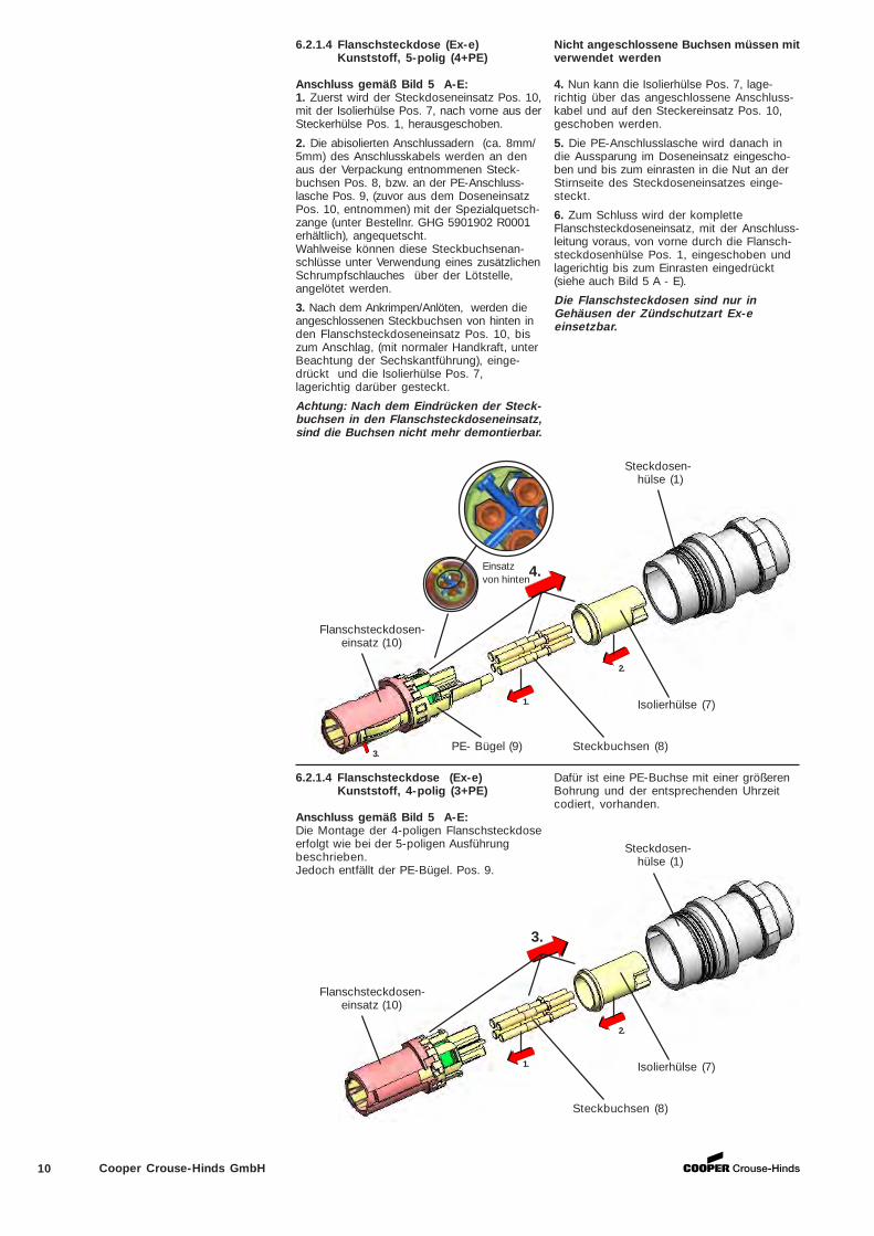
6.2.1.4 Flanschsteckdose (Ex-e)Kunststoff, 5-polig (4+PE)
Anschluss gemäß Bild 5 A-E:1. Zuerst wird der Steckdoseneinsatz Pos. 10,mit der Isolierhülse Pos. 7, nach vorne aus derSteckerhülse Pos. 1, herausgeschoben.
2. Die abisolierten Anschlussadern (ca. 8mm/5mm) des Anschlusskabels werden an denaus der Verpackung entnommenen Steck-buchsen Pos. 8, bzw. an der PE-Anschluss-lasche Pos. 9, (zuvor aus dem DoseneinsatzPos. 10, entnommen) mit der Spezialquetsch-zange (unter Bestellnr. GHG 5901902 R0001erhältlich), angequetscht.Wahlweise können diese Steckbuchsenan-schlüsse unter Verwendung eines zusätzlichenSchrumpfschlauches über der Lötstelle,angelötet werden.
3. Nach dem Ankrimpen/Anlöten, werden dieangeschlossenen Steckbuchsen von hinten inden Flanschsteckdoseneinsatz Pos. 10, biszum Anschlag, (mit normaler Handkraft, unterBeachtung der Sechskantführung), einge-drückt und die Isolierhülse Pos. 7,lagerichtig darüber gesteckt.
Achtung: Nach dem Eindrücken der Steck-buchsen in den Flanschsteckdoseneinsatz,sind die Buchsen nicht mehr demontierbar.
Flanschsteckdosen- einsatz (10)
PE- Bügel (9) Steckbuchsen (8)
Isolierhülse (7)
Steckdosen-hülse (1)
2.
1.
3.
Flanschsteckdosen- einsatz (10)
Steckbuchsen (8)
Isolierhülse (7)
Steckdosen-hülse (1)
6.2.1.4 Flanschsteckdose (Ex-e)Kunststoff, 4-polig (3+PE)
Anschluss gemäß Bild 5 A-E:Die Montage der 4-poligen Flanschsteckdoseerfolgt wie bei der 5-poligen Ausführungbeschrieben.Jedoch entfällt der PE-Bügel. Pos. 9.
Dafür ist eine PE-Buchse mit einer größerenBohrung und der entsprechenden Uhrzeitcodiert, vorhanden.
Nicht angeschlossene Buchsen müssen mitverwendet werden
4. Nun kann die Isolierhülse Pos. 7, lage-richtig über das angeschlossene Anschluss-kabel und auf den Steckereinsatz Pos. 10,geschoben werden.
5. Die PE-Anschlusslasche wird danach indie Aussparung im Doseneinsatz eingescho-ben und bis zum einrasten in die Nut an derStirnseite des Steckdoseneinsatzes einge-steckt.
6. Zum Schluss wird der kompletteFlanschsteckdoseneinsatz, mit der Anschluss-leitung voraus, von vorne durch die Flansch-steckdosenhülse Pos. 1, eingeschoben undlagerichtig bis zum Einrasten eingedrückt(siehe auch Bild 5 A - E).
Die Flanschsteckdosen sind nur inGehäusen der Zündschutzart Ex-eeinsetzbar.
Einsatzvon hinten
11Cooper Crouse-Hinds GmbH
6.2.2 QUICKON® Anschlussfür Stecker und Kupplung4-polig (3+PE)
Um eine sichere Kontaktgabe bei denQUICKON® Klemmen zu gewährleistensind die erforderlichen Leitungen gemäßden technischen Produktdaten zuverwenden.
Die Adern des Anschlusskabels dürfennicht Abisoliert werden.
Es ist dabei darauf zu achten, dass dieschon einmal angeschlossene Kontakt-stelle an der Ader, abgeschnitten wird. Beider Verwendung einer neuen Leitungmuss der gleiche Aderquerschnittgewählt werden.
Leitungsparameter
D1=Leitungs-durchmesser(sieheTechnischeDaten)
D2=Einzelader-durchmesser< 2,5mm
D3=Litzendurch-messer mind.0,1mm
QUICKON® Anschluss
6.2.2.1 Stecker (Ex-e) Kunststoff/Metall4-polig (3+PE)
Anschluss gemäß Bild 6 A-G:1. Am Stecker wird zuerst das DruckstückPos. 2, durch vorheriges lösen derArretierungsschraube Pos. 3, aus der Stek-kerhülse Pos. 17, herausgedreht und die Ein-satzteile Pos. 4 - 6, 18+19 aus der Stecker-hülse Pos. 17, nach hinten herausgezogen.
2. Das auf ca. 30 mm abgemantelte An-schlusskabel (siehe auch Seite 3) wird durchdas Druckstück Pos. 2, der ZugentlastungPos. 4, der Dichtung Pos. 5, sowie derDruckscheibe (Schirmauflage) Pos. 6durchgefädelt.
3. Die einzelnen Adern werden dann durchdie gekennzeichneten Aderführungen desSpleissrings Pos. 19, durchgeführt unddie überstehenden Enden Bündig an derStirnseite des Spleissringes Pos. 19,abgeschnitten.
4. Zum Zusammenbau wird der SpleissringPos. 19, lagerichtig in den QUICKON®Einsatz Pos. 18, (in der Steckerhülse Pos. 17)mit Handkraft eingedrückt und dieEinsatzteile (Druckscheibe, Dichtung,Zugenlastung) werden in die Steckerhülseeingeschoben.
Überwurfmutter (16) Steckerhülse (17)
QUICKON® Einsatz (18)
Druckscheibe Schirmauflage (6)
Spleissring (19)
Arretierungs- Dichtung (5) schraube (3)
Zugent-lastung (4) Druckstück
(2)
2
1 4 / PE
3
1. 2.
Achtung: Beim Zusammenstecken ist aufdie richtige Lage der Führungsnase desQUICKON® Einsatzes zur Führungsnutdes Spleissringes zu achten.
5. Nun wird das Druckstück Pos. 2, biszur Dicht- und Zugentlastungswirkung(Prüfdrehmoment siehe Technische Daten)wieder auf die Steckerhülse Pos. 17,aufgeschraubt und mit der Arretierungs-schraube Pos. 3, gesichert.Durch das Festdrehen des Druckstückeswird der korrekte Kontakt zwischen denSteckerstiften und dem Anschlusskabel ander QUICKON® Klemmstelle hergestellt.
Zum Lösen der Verbindung ist in umgekehr-ter Reihenfolge vorzugehen (siehe auch Bild 6A-G).
12 Cooper Crouse-Hinds GmbH
Führungsnut
Kupplungshülse (1)
Druckstück (2)
Arretierungs- schraube (3)
QUICKON®Einsatz (18)
6.2.2.2 Kupplung (Ex-e) Kunststoff/Metall4-polig (3+PE)
Anschluss gemäß Bild 6 A-G:1. An der Kupplung wird zuerst das Druck-stück Pos. 2, durch vorheriges lösen derArretierungsschraube Pos. 3, aus der Kupp-lungshülse Pos. 1, herausgedreht und dieEinsatzteile Pos.4- 6,18+19, aus der Kupp-lungshülse nach hinten herausgezogen.
2. Das auf ca. 30mm abgemantelte An-schlusskabel (siehe auch Seite 3) wird durchdas Druckstück Pos. 2, der ZugentlastungPos. 4, der Dichtung Pos. 5, sowie derDruckscheibe (Schirmauflage) Pos. 6,durchgefädelt.
3. Die einzelnen Adern werden dann durchdie gekennzeichneten Aderführungen desSpleissrings Pos. 19, durchgeführt unddie überstehenden Enden Bündig an derStirnseite des Spleissringes Pos. 19,abgeschnitten.
4. Zum Zusammenbau wird der Spleiss=ringPos. 19, lagerichtig in den QUICKON® EinsatzPos. 18, (in der Kupplungshülse Pos. 1) mitHandkraft eingedrückt und dieEinsatzteile (Druckscheibe, Dichtung,Zugenlastung) werden in die Kupplungs-hülse eingeschoben.
Bild 6
B Leiter in Spleissring einfädeln und .....
A Einzelteile
D Zusammenstecken mit Einsatz
F Den angeschlossenen Stecker bzw.Kupplungseinsatz in die Hülseeinführen und ....
Spleissring (19)
Dichtung (5)
Zugentlastung (4)
Druckscheibe /Schirmauflage (6)
G ... Stecker/Kupplung durch aufdrehender Druck- und Arretierungsschraubekomplettieren.
2
1
E Zusammenstecken mit Hülse.
Auf Führungsnut achten.
C ... Bündig am Spleissring abschnei-den.
1.
2.
Achtung: Beim Zusammenstecken ist aufdie richtige Lage der Führungsnase desQUICKON® Einsatzes zur Führungsnutdes Spleissringes zu achten.
5. Nun wird das Druckstück Pos. 2, bis zurDicht- und Zugentlastungswirkung (Prüf-drehmoment siehe Technische Daten) wiederauf die Kupplungshülse Pos. 1, aufge-schraubt und mit der ArretierungsschraubePos. 3, gesichert.Durch das Festdrehen des Druckstückeswird der korrekte Kontakt zwischen denSteckbuchsen und dem Anschlusskabel ander QUICKON®-Klemmstelle hergestellt.
Zum Lösen der Verbindung ist in umgekehr-ter Reihenfolge vorzugehen (siehe auch Bild 6A-G).
13Cooper Crouse-Hinds GmbH
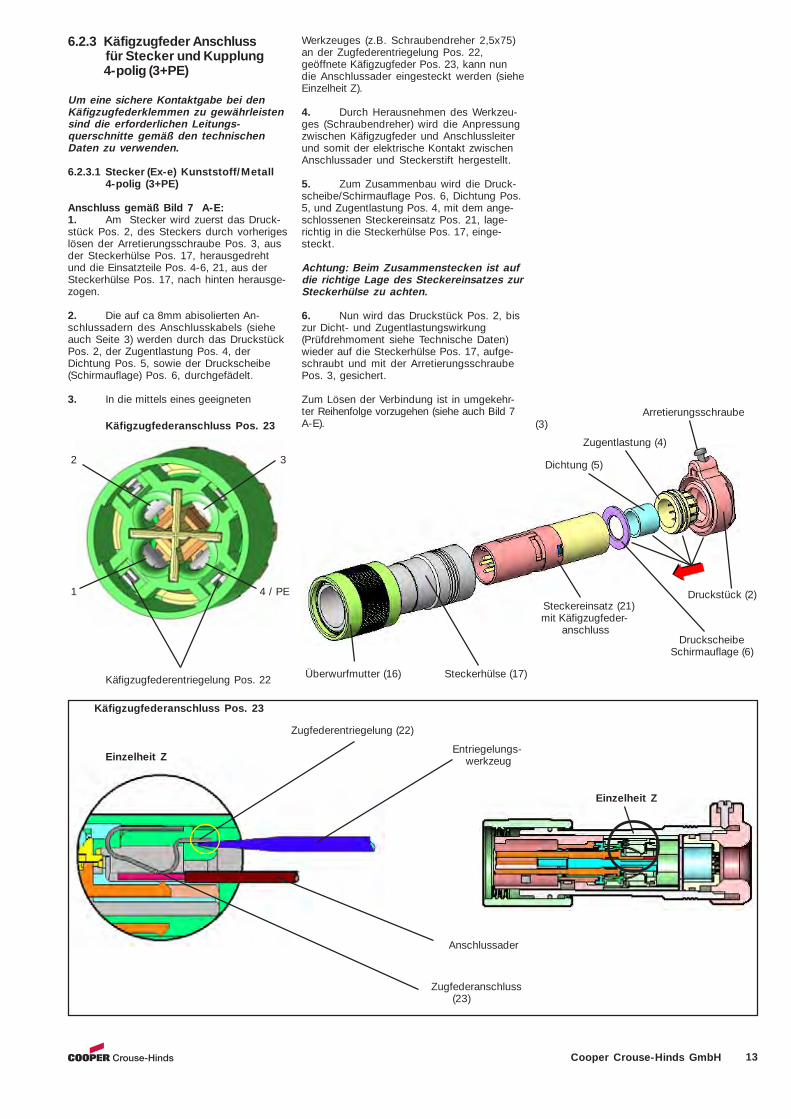
6.2.3 Käfigzugfeder Anschlussfür Stecker und Kupplung4-polig (3+PE)
Um eine sichere Kontaktgabe bei denKäfigzugfederklemmen zu gewährleistensind die erforderlichen Leitungs-querschnitte gemäß den technischenDaten zu verwenden.
6.2.3.1 Stecker (Ex-e) Kunststoff/Metall4-polig (3+PE)
Anschluss gemäß Bild 7 A-E:1. Am Stecker wird zuerst das Druck-stück Pos. 2, des Steckers durch vorherigeslösen der Arretierungsschraube Pos. 3, ausder Steckerhülse Pos. 17, herausgedrehtund die Einsatzteile Pos. 4-6, 21, aus derSteckerhülse Pos. 17, nach hinten herausge-zogen.
2. Die auf ca 8mm abisolierten An-schlussadern des Anschlusskabels (sieheauch Seite 3) werden durch das DruckstückPos. 2, der Zugentlastung Pos. 4, derDichtung Pos. 5, sowie der Druckscheibe(Schirmauflage) Pos. 6, durchgefädelt.
3. In die mittels eines geeigneten
Einzelheit Z
Käfigzugfederanschluss Pos. 23
Einzelheit Z
Zugfederanschluss(23)
Käfigzugfederanschluss Pos. 23
1 4 / PE
Käfigzugfederentriegelung Pos. 22 Überwurfmutter (16) Steckerhülse (17)
Steckereinsatz (21) mit Käfigzugfeder- anschluss
Druckscheibe Schirmauflage (6)
Druckstück (2)
Arretierungsschraube(3)
Entriegelungs- werkzeug
Anschlussader
Dichtung (5)
Zugfederentriegelung (22)
Zugentlastung (4)
2 3
Werkzeuges (z.B. Schraubendreher 2,5x75)an der Zugfederentriegelung Pos. 22,geöffnete Käfigzugfeder Pos. 23, kann nundie Anschlussader eingesteckt werden (sieheEinzelheit Z).
4. Durch Herausnehmen des Werkzeu-ges (Schraubendreher) wird die Anpressungzwischen Käfigzugfeder und Anschlussleiterund somit der elektrische Kontakt zwischenAnschlussader und Steckerstift hergestellt.
5. Zum Zusammenbau wird die Druck-scheibe/Schirmauflage Pos. 6, Dichtung Pos.5, und Zugentlastung Pos. 4, mit dem ange-schlossenen Steckereinsatz Pos. 21, lage-richtig in die Steckerhülse Pos. 17, einge-steckt.
Achtung: Beim Zusammenstecken ist aufdie richtige Lage des Steckereinsatzes zurSteckerhülse zu achten.
6. Nun wird das Druckstück Pos. 2, biszur Dicht- und Zugentlastungswirkung(Prüfdrehmoment siehe Technische Daten)wieder auf die Steckerhülse Pos. 17, aufge-schraubt und mit der ArretierungsschraubePos. 3, gesichert.
Zum Lösen der Verbindung ist in umgekehr-ter Reihenfolge vorzugehen (siehe auch Bild 7A-E).
14 Cooper Crouse-Hinds GmbH
Kupplungseinsatz (20)mit Käfigzugfederanschluss
Druckscheibe /Schirmauflage (6)
Druckstück (2)
Arretierungs- schraube (3)
Dichtung (5)
Zugentlastung (4)
Kupplungshülse (1)
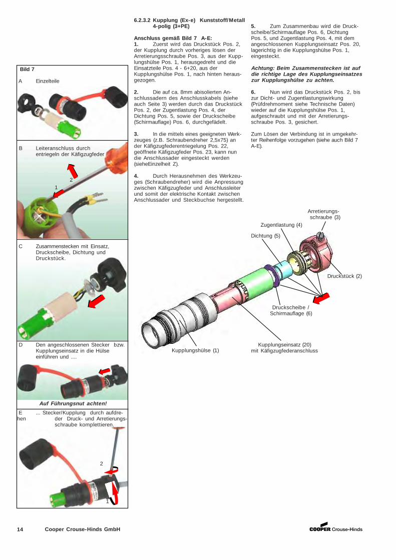
6.2.3.2 Kupplung (Ex-e) Kunststoff/Metall4-polig (3+PE)
Anschluss gemäß Bild 7 A-E:1. Zuerst wird das Druckstück Pos. 2,der Kupplung durch vorheriges lösen derArretierungsschraube Pos. 3, aus der Kupp-lungshülse Pos. 1, herausgedreht und dieEinsatzteile Pos. 4 - 6+20, aus derKupplungshülse Pos. 1, nach hinten heraus-gezogen.
2. Die auf ca. 8mm abisolierten An-schlussadern des Anschlusskabels (sieheauch Seite 3) werden durch das DruckstückPos. 2, der Zugentlastung Pos. 4, derDichtung Pos. 5, sowie der Druckscheibe(Schirmauflage) Pos. 6, durchgefädelt.
3. In die mittels eines geeigneten Werk-zeuges (z.B. Schraubendreher 2,5x75) ander Käfigzugfederentriegelung Pos. 22,geöffnete Käfigzugfeder Pos. 23, kann nundie Anschlussader eingesteckt werden(sieheEinzelheit Z).
4. Durch Herausnehmen des Werkzeu-ges (Schraubendreher) wird die Anpressungzwischen Käfigzugfeder und Anschlussleiterund somit der elektrische Kontakt zwischenAnschlussader und Steckbuchse hergestellt.
Bild 7
B Leiteranschluss durchentriegeln der Käfigzugfeder
A Einzelteile
C Zusammenstecken mit Einsatz,Druckscheibe, Dichtung undDruckstück.
2
1
D Den angeschlossenen Stecker bzw.Kupplungseinsatz in die Hülseeinführen und ....
E ... Stecker/Kupplung durch aufdre-hen der Druck- und Arretierungs-
schraube komplettieren.
Auf Führungsnut achten!
21
5. Zum Zusammenbau wird die Druck-scheibe/Schirmauflage Pos. 6, DichtungPos. 5, und Zugentlastung Pos. 4, mit demangeschlossenen Kupplungseinsatz Pos. 20,lagerichtig in die Kupplungshülse Pos. 1,eingesteckt.
Achtung: Beim Zusammenstecken ist aufdie richtige Lage des Kupplungseinsatzeszur Kupplungshülse zu achten.
6. Nun wird das Druckstück Pos. 2, biszur Dicht- und Zugentlastungswirkung(Prüfdrehmoment siehe Technische Daten)wieder auf die Kupplungshülse Pos. 1,aufgeschraubt und mit der Arretierungs-schraube Pos. 3, gesichert.
Zum Lösen der Verbindung ist in umgekehr-ter Reihenfolge vorzugehen (siehe auch Bild 7A-E).
15Cooper Crouse-Hinds GmbH
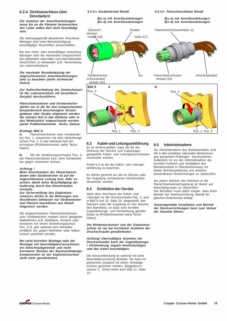
6.2.4.2 Flanschsteckdose Metall
(Ex-e) mit Anschlussleitungen(Ex-d) mit Anschlussleitungen
6.2.4.1 Gerätestecker Metall
(Ex-e) mit Anschlussleitungen(Ex-d) mit Anschlussleitungen
Pos. 3
Pos. 1 Pos. 2 Pos. 1 Pos. 2
Überwurf- Geräte-stecker- mutter (16) hülse (17)
Flanschsteckdosenhülse (1)
Flanschsteckdosen- Anschlusskabel einsatz (10)
Gerätestecker- An-schlusskabel einsatz (10)
Bild 8 A Pos. 3
6.2.4 Direktanschluss überEinzeladern
Die Isolation der Anschlussleitungenmuss bis an die Klemme heranreichen.Der Leiter selbst darf nicht beschädigtsein.
Die ordnungsgemäß abisolierten Anschluss-leitungen sind unter Berücksichtigungeinschlägiger Vorschriften anzuschließen.
Bei den mehr- oder feindrähtigen Anschluss-leitungen sind die Aderenden entsprechendden geltenden nationalen und internationalenVorschriften zu behandeln (z.B. Verwendungvon Aderendhülsen).
Die maximale Strombelastung derangeschlossenen Anschlussleitungensind zu beachten (siehe technischeDaten).
Zur Aufrechterhaltung der Zündschutzartist der Leiteranschluss mit besondererSorgfalt durchzuführen.
Flanschsteckdosen und Gerätesteckerdürfen nur in die für den entsprechendenEinsatzbereich bescheinigten Schutz-gehäuse oder Geräte eingesetzt werden.Sie müssen fest in das Gehäuse oder indas Winkelstück eingeschraubt werden(siehe Prüfdrehmomente Techn. Daten).
Montage Bild 8:A. Flanschsteckdose oder Gerätestek-ker Pos. 1, zusammen mit dem Verdrehungs-schutz Pos. 2, in das Gehäuse fest ein-schrauben (Prüfdrehmoment siehe Techn.Daten).
B. Mit der Arretierungsschraube Pos. 3,die Flanschsteckdose bzw. dern Gerätestek-ker gegen verdrehen sichern.
Achtung !Beim Einschrauben der Flanschsteck-dosen oder Gerätestecker ist auf dieangeschlossene Leitung bzw. Ader zuachten, damit keine Beschädigung derIsolierung durch das Einschraubenentsteht.Zur Sicherstellung des Explosions-schutzes dürfen in die Bohrungen vondruckfesten Gehäusen nur Gerätesteckerund Flansch-steckdosen aus Metalleingesetzt werden.
Die eingeschraubten Flanschsteckdosen,oder Gerätestecker müssen durch geeigneteMaßnahmen (z.B. Einkleben, Kontern oderArretieren mit einem VerdrehungsschutzPos. 2+3, (der optional vom Herstellererhältlich ist), gegen Verdrehen oder Selbst-lockern gesichert werden.
Bei nicht korrekter Montage oder derMontage mit beschädigten/verschmutz-ten Einschraubgewinde und nichtkorrektem Stecken der Steckverbindungs-komponenten ist der Explosionsschutznicht mehr gewährleistet.
B
6.3 Kabel-und LeitungseinführungEs ist sicherzustellen, dass die für dieDichtung der Stecker und Kupplungengeeigneten Kabel- und Leitungsdurchmesserverwendet werden.
Punkt 6.2 ist bei der Kabel- und Leitungs-einführung zu beachten.
Es dürfen generell nur die im Stecker oderder Kupplung vorhandenen Dichteinsätzeverwendet werden.
6.4 Schließen der GeräteNach dem Anschluss der Kabel- undLeitungen ist die Druckschraube Pos. 2, (wiein Bild 9 und 10, Seite 15 dargestellt), desSteckers oder der Kupplung so fest anzuzie-hen (handfest), so dass eine korrekteZugentlastungs- und Dichtwirkung gewähr-leistet ist (Prüfdrehmoment siehe Techn.Daten).
Die Mindestschutzart und der Explosions-schutz ist nur bei korrektem Anziehen derDruckschraube gewährleistet.
Achtung! Übermäßiges Anziehen derDruckschraube kann die Zugentlastungs-/ Dichtwirkung negativ beeinträchtigenund das Kabel beschädigen.
Die Steckverbindung ist optional mit einerAbschließvorrichtung lieferbar. Sie kann imgesteckten Zustand mit einem Vorhänge-schloss gesichert werden, (Bügeldurch-messer 3 - 6mm) siehe auch Bild 11, Seite15.
6.5 InbetriebnahmeVor Inbetriebnahme des Betriebsmittels sinddie in den einzelnen nationalen Bestimmun-gen genannten Prüfungen durchzuführen.Außerdem ist vor der Inbetriebnahme diekorrekte Funktion und Installation desBetriebsmittels in Übereinstimmung mitdieser Betriebsanleitung und anderenanwendbaren Bestimmungen zu überprüfen.
Vor jedem Stecken des Steckers in dieFlanschsteckdose/Kupplung ist dieser aufBeschädigungen zu überprüfen.Der Betreiber muss dafür sorgen, dass beimBetrieb der Steckvorrichtung überall eingleiches Erdpotential anliegt.
Unsachgemäße Installation und Betriebder Steckvorrichtungen kann zum Verlustder Garantie führen.
16 Cooper Crouse-Hinds GmbH
Bild 9
2
3
4
Pos. 6, 5, 4 Pos. 2
Pos. 3
Pos. 2 Druckstück Pos. 3 Arretierungsschraube Pos. 4 Zugentlastung Pos. 5 Dichtung Pos. 6 Druckscheibe/Schirmauflage
1
Kupplung und Flanschsteckdose
Bestellnummer: GHG 510 1903 R0001
Ersatzschutzkappe aus Kunststoff für
Bild 11
7 Instandhaltung / WartungDie für die Wartung / Instandhaltung vonelektrischen Betriebsmitteln inexplosionsgefährdeten Bereichengeltenden nationalen Bestimmungen sindeinzuhalten (EN/IEC 60079-17).Vor Öffnen des Gehäuses Spannungs-freiheit sicherstellen oder geeigneteSchutzmaßnahmen ergreifen.
Die erforderlichen Wartungsintervalle sindanwendungsspezifisch und daher in Abhän-gigkeit von den Einsatzbedingungen vomBetreiber festzulegen.Im Rahmen der Wartung sind vor allem dieTeile, von denen die Zündschutzart abhängt,zu prüfen (z.B. Unversehrtheit des Gehäu-ses, der Dichtungen, der Steckerstifte,Steckbuchsen etc.).Sollte bei einer Wartung festgestellt werden,dass Instandsetzungsarbeiten erforderlichsind, ist Abschnitt 8 dieser Betriebsanleitungzu beachten.
8 Reparatur / Instand-setzung / Änderungen
Instandsetzungsarbeiten / Reparaturendürfen nur mit Originalersatzteilen desHerstellers vorgenommen werden.
Bei Schäden den Steckerstiften undSteckbuchsen, sind diese sofort auszu-wechseln bzw. das betroffene Betriebs-mittel an den Hersteller zur Reparaturzurückzugeben.Spaltbegrenzungsflächen dürfen nach-träglich weder bearbeitet noch lackiertwerden.Bei Schäden an der druckfesten Kapse-lung ist nur ein Austausch zulässig. ImZweifelsfalle ist das betroffene Betriebs-mittel an den Hersteller zur Reparaturzurückzugeben.
Bild 10 Abbildung mitSchirmauflage Druckscheibe / Druckstück
(2)Schirmauflage (6)
Schirmlitzen Zugentlastung Anschluss- der Leitung mit Dichtung (4,5) leitung
Stecker und Gerätestecker
Bestellnummer: GHG 510 1903 R0002
Das Auswechseln der Steckerstifte oder derSteckbuchsen ist nur beim QUICKON®Anschluss möglich. Zum Auswechseln derStifte oder Buchsen ist wie unter Punkt 6.2.1beschrieben zu verfahren.
Reparaturen, die den Explosionsschutzbetreffen, dürfen nur vom Hersteller odereiner qualifizierten Elektrofachkraft inÜbereinstimmung mit national geltendenRegeln durchgeführt werden(EN/IEC 60079-19).Umbauten oder Änderungen am Betriebs-mittel sind nicht gestattet.
9 Entsorgung / Wiederver-wertungBei der Entsorgung des Betriebsmittels sind diejeweils geltenden nationalen Abfallbeseitigungs-vorschriften zu beachten.Zur Erleichterung der Wiederverwertbarkeit vonEinzelteilen sind Kunststoffteile mit dem Kennzei-chen des verwendeten Kunststoffes versehen.
Programmänderungen und -ergänzungen sindvorbehalten.
17Cooper Crouse-Hinds GmbH
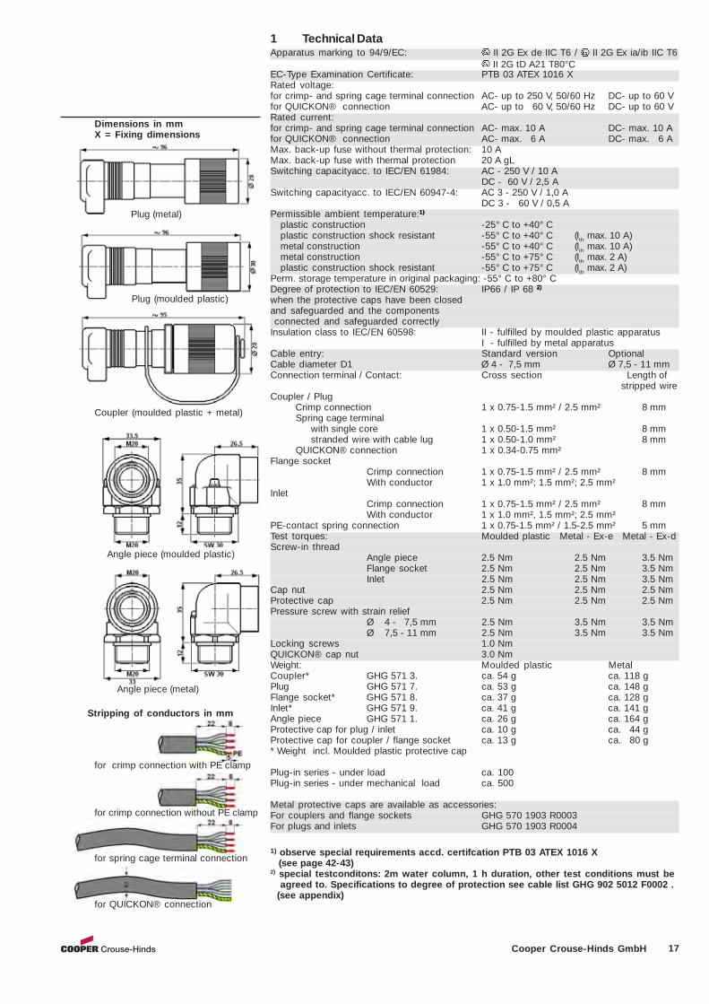
1 Technical DataApparatus marking to 94/9/EC: II 2G Ex de IIC T6 / II 2G Ex ia/ib IIC T6
II 2G tD A21 T80°CEC-Type Examination Certificate: PTB 03 ATEX 1016 XRated voltage:for crimp- and spring cage terminal connection AC- up to 250 V, 50/60 Hz DC- up to 60 Vfor QUICKON® connection AC- up to 60 V, 50/60 Hz DC- up to 60 VRated current:for crimp- and spring cage terminal connection AC- max. 10 A DC- max. 10 Afor QUICKON® connection AC- max. 6 A DC- max. 6 AMax. back-up fuse without thermal protection: 10 AMax. back-up fuse with thermal protection 20 A gLSwitching capacityacc. to IEC/EN 61984: AC - 250 V / 10 A
DC - 60 V / 2,5 ASwitching capacityacc. to IEC/EN 60947-4: AC 3 - 250 V / 1,0 A
DC 3 - 60 V / 0,5 APermissible ambient temperature:1)1)1)1)1)
plastic construction -25° C to +40° Cplastic construction shock resistant -55° C to +40° C (Ith max. 10 A)metal construction -55° C to +40° C (Ith max. 10 A)metal construction -55° C to +75° C (Ith max. 2 A)plastic construction shock resistant -55° C to +75° C (Ith max. 2 A)
Perm. storage temperature in original packaging: -55° C to +80° CDegree of protection to IEC/EN 60529: IP66 / IP 68 2)2)2)2)2)
when the protective caps have been closedand safeguarded and the components connected and safeguarded correctlyInsulation class to IEC/EN 60598: II - fulfilled by moulded plastic apparatus
I - fulfilled by metal apparatusCable entry: Standard version OptionalCable diameter D1 Ø 4 - 7,5 mm Ø 7,5 - 11 mmConnection terminal / Contact: Cross section Length of
stripped wireCoupler / Plug Crimp connection 1 x 0.75-1.5 mm² / 2.5 mm² 8 mm Spring cage terminal
with single core 1 x 0.50-1.5 mm² 8 mmstranded wire with cable lug 1 x 0.50-1.0 mm² 8 mm
QUICKON® connection 1 x 0.34-0.75 mm²Flange socket
Crimp connection 1 x 0.75-1.5 mm² / 2.5 mm² 8 mmWith conductor 1 x 1.0 mm²; 1.5 mm²; 2.5 mm²
InletCrimp connection 1 x 0.75-1.5 mm² / 2.5 mm² 8 mmWith conductor 1 x 1.0 mm², 1.5 mm²; 2.5 mm²
PE-contact spring connection 1 x 0.75-1.5 mm² / 1.5-2.5 mm² 5 mmTest torques: Moulded plastic Metal - Ex-e Metal - Ex-dScrew-in thread
Angle piece 2.5 Nm 2.5 Nm 3.5 NmFlange socket 2.5 Nm 2.5 Nm 3.5 NmInlet 2.5 Nm 2.5 Nm 3.5 Nm
Cap nut 2.5 Nm 2.5 Nm 2.5 NmProtective cap 2.5 Nm 2.5 Nm 2.5 NmPressure screw with strain relief
Ø 4 - 7,5 mm 2.5 Nm 3.5 Nm 3.5 NmØ 7,5 - 11 mm 2.5 Nm 3.5 Nm 3.5 Nm
Locking screws 1.0 NmQUICKON® cap nut 3.0 NmWeight: Moulded plastic MetalCoupler* GHG 571 3. ca. 54 g ca. 118 gPlug GHG 571 7. ca. 53 g ca. 148 gFlange socket* GHG 571 8. ca. 37 g ca. 128 gInlet* GHG 571 9. ca. 41 g ca. 141 gAngle piece GHG 571 1. ca. 26 g ca. 164 gProtective cap for plug / inlet ca. 10 g ca. 44 gProtective cap for coupler / flange socket ca. 13 g ca. 80 g* Weight incl. Moulded plastic protective cap
Plug-in series - under load ca. 100Plug-in series - under mechanical load ca. 500
Metal protective caps are available as accessories:For couplers and flange sockets GHG 570 1903 R0003For plugs and inlets GHG 570 1903 R0004
1) observe special requirements accd. certifcation PTB 03 ATEX 1016 X (see page 42-43)2) special testconditons: 2m water column, 1 h duration, other test conditions must be agreed to. Specifications to degree of protection see cable list GHG 902 5012 F0002 . (see appendix)
Dimensions in mmX = Fixing dimensions
Stripping of conductors in mm
for crimp connection with PE clamp
for spring cage terminal connection
for QUICKON® connection
Coupler (moulded plastic + metal)
Plug (moulded plastic)
Plug (metal)
Angle piece (moulded plastic)
Angle piece (metal)
for crimp connection without PE clamp
18 Cooper Crouse-Hinds GmbH
2 Safety instructionsRead these operating instructions
for the plug and socket systemsthrough carefully beforeinstallation and putting the
apparatus into service.
The connection of plug and socketsystems shall only be carried out byqualified personnel.Plug and socket systems of the type GHG57. are not suited for use in Zone 0 andZone 20 areas.The temperature class and type ofprotection stated on the apparatus shallbe observed.TThe requirements of the EN 61241-0and -1 regarding excessive dust depositsand temperature to be considered fromthe user.They shall be used for their intended pur-pose and shall be in an undamaged andperfect state.Only original manufacturer parts may beused as replacements and for repairs.
Repairs that affect the explosionprotection may only be carried out by themanufacturer or by a qualified electricianin compliance with the respective nationalregulations.
Before being put into use, the plug andsocket systems shall be checked inaccordance with Section 6 of the namedinstructions.The flange sockets and inlets may only beused with the associated, undamagedplugs and couplers.The plug and socket system may only beconnected or disconnected at max. 250 VAC under load and a rated current of 10 A(6A/60 V for QUICKON® version).In accordance with IEC/EN 60079-1, theinstallation of flameproof plug and socketsystems (flange socket/inlet) is limited toenclosures with a volume of max. 2 dm³.In order to guarantee the explosionprotection, only inlets and flange socketsmade of metal may be fitted in theboreholes of flameproof enclosures.
When opened, the live plug and socketsystem components shall be sealedimmediately after disconnection using theprotective cap. Here it is necessary toensure that it is closed correctly,otherwise the minimum degree ofprotection and the explosion protectionare no longer guaranteed.
Unused components are to be kept sealedwith the protective cap.
Flange sockets and inlets may only beused in protective enclosure or apparatusthat have been certified for the respectiveapplication.When screwing in the flange sockets orinlets, attention shall be paid toconnected cables or wires to prevent anydamage to the insulation.The metal flang sockets and inlets shallbe incorporated in the earth potentialequalization.
Dimensions in mmX = Fixing dimensions
3 Conformity with standardsThe plug and socket system is conform to thestandards specified in the EC-Declaration ofconformity, enclosed separately.94/9/ EC: Equipment and protective systemsintended for use in potentially explosive at-mospheres.The plug and socket systems fulfil furtherrequirements, such as the EC directive onelectromagnetic compatibility(2004/108/EC)They have been designed, manufacturedand tested according to the state of the artand to DIN EN ISO 9001:2008 andEN ISO/IEC 80079-34:2011.
4 Field of applicationThe plug and socket systems GHG 57. areintended for use in potentially explosiveatmospheres in Zones 1, Zones 2 andZones 21, Zones 22 in accordance withIEC/EN 60079-10-1 and IEC/EN 60079-10-2.
The enclosure materials used, including anyexternal metal parts, are high qualitymaterials that ensure a corrosion resistanceand resistance to chemical substancesaccording to the requirements for use in a„normal industrial atmosphere“- impact resistant polyamide- nickel-plated brass- special steel AISI 316 L.When used in extremely aggressiveatmospheres, the additional data relating tothe chemical resistance of the plastics beingused shall be taken from the data sheetGHG 902 4001 P0001.
5 Application / PropertiesThe plug and socket systems GHG 57. areused for the power supply of portable, localcontrols, electrical installations and portableelectric machines and drives in potentiallyexplosive atmospheres.They are also used for the quick connectionof explosion-protected electrical apparatus inpotentially explosive atmospheres andindustrial areas.
The plug and socket systems can be usedup to max. 10A/250V (6A/60 V QUICKON®version, see Technical Data).
The plug and socket system may only beconnected or disconnected under loadacc. to technical data.The apparatus connected to the plugshall be suited for the mains voltagebeing applied.
3
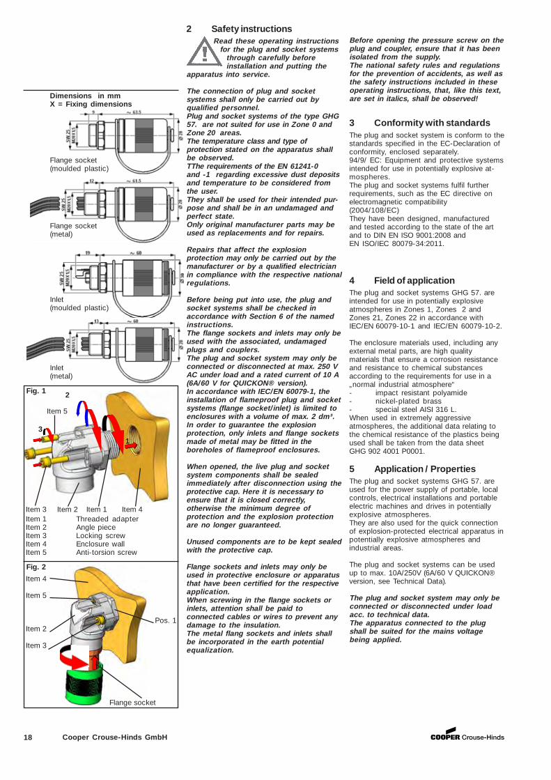
2
1
Item 3 Item 2 Item 1 Item 4 Item 1 Threaded adapter Item 2 Angle piece Item 3 Locking screw Item 4 Enclosure wall Item 5 Anti-torsion screw
Item 4
Item 5
Pos. 1 Item 2
Item 3
Flange socket
Fig. 2
Item 5
Inlet(moulded plastic)
Inlet(metal)
Flange socket(metal)
Flange socket(moulded plastic)
Fig. 1
Before opening the pressure screw on theplug and coupler, ensure that it has beenisolated from the supply.The national safety rules and regulationsfor the prevention of accidents, as well asthe safety instructions included in theseoperating instructions, that, like this text,are set in italics, shall be observed!
19Cooper Crouse-Hinds GmbH
6.1 Mounting
Preferably flange sockets and inlets shall bemounted with the plug opening facingdownwards.
Flange sockets, inlets and angle piecesmay only be installed in protectiveapparatus or enclosures that have beencertified for the respective application.
When mounting flange sockets, inlets or anglepieces in a flameproof enclosure, inaccordance with IEC/EN 60079-1, Table 3,the volume of the enclosure or of theapparatus is limited to max. 2 dm³.
The threaded boreholes in the flameproofenclosure or built-in apparatus shall fulfilthe minimum requirements according toIEC/EN 60079-1.
The plug and sockets system components,flange socket, inlet or angle piece, as well asthe respective boreholes and screw-inthreads of the enclosures or apparatus shallbe checked prior to mounting to ensure thatthey are not damaged and in a clean state.
Before screwing-in components, ensure thatthe threads of the screw-in components(flange socket, inlet or angle piece)corresponds to that of the threaded boreholein the enclosure or apparatus.
When mounting screw-in components, itis necessary to ensure that the sealingring is in the correct position and that it isnot damaged. Components made of metalonly may be used in flameproofenclosures.The screw-in components shall bescrewed in tightly into the enclosure (seeTechnical Data for test torque).
To adapt the position of the screwed-in anglepiece in relation to the entry piece, undo thescrews, Items 3 and 5, turn the angle piece,Item 2, until it is in the desired position andscrew the screws, Item 3, back into therespective visible threaded holes. Then, bymeans of the anti-torsion screw, Item 5, theangle piece is safeguarded against twisting(see Fig. 1, page 4).
Suitable measures shall be applied (e.g.adhesive, locking and retaining with anti-torsion screw, Item 5, see also Fig. 2, page 4)to safeguard screwed-in flange sockets,inlets or angle pieces against twisting or self-loosening.
The explosion protection is no longerguaranteed if mounted incorrectly or ifmounted in a damaged/dirty screw-inthread.
For an easy identification of the differentversions oloured rubber rings are included.The rubber rings shall be slipped onto thehousing. (Fig, 3b)(see Page 2)
6 InstallationThe relevant national regulations and thegenerally recognized rules of engineeringapply for the installation and operation(IEC/EN 60079-14).
For information on connection cables seeData Sheet GHG 902 5012 F0001 on ourinternet website: www.ceag.de.
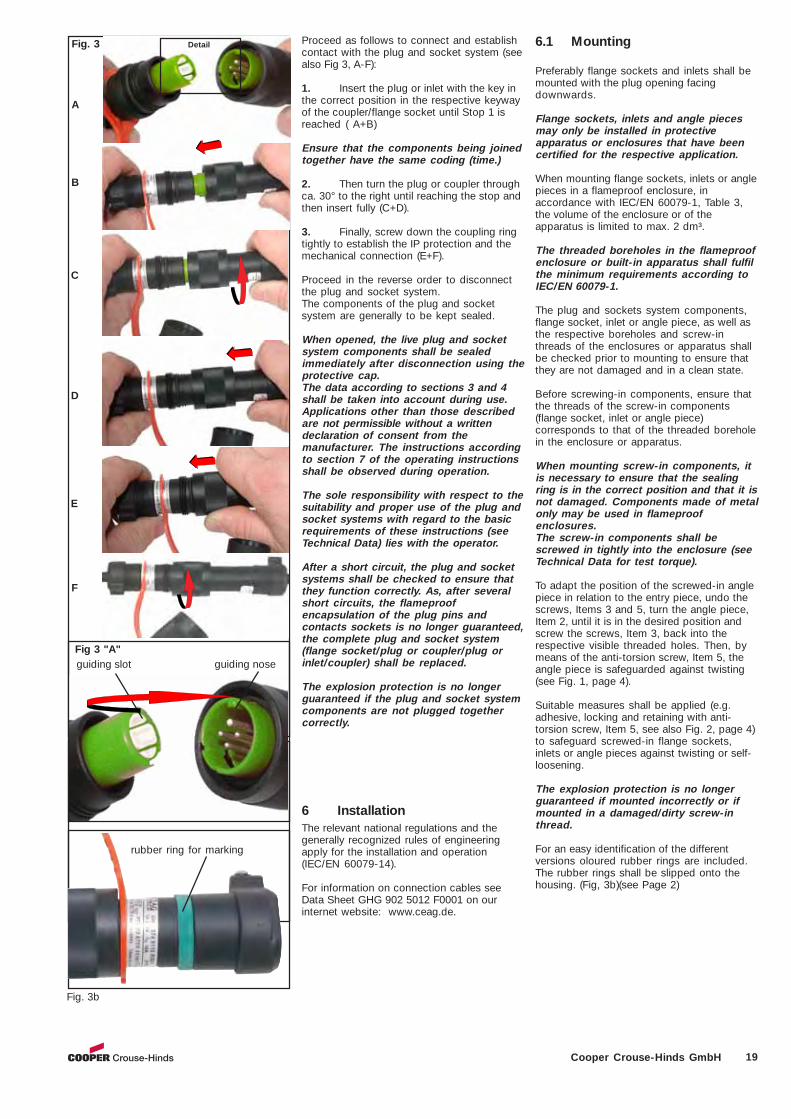
Proceed as follows to connect and establishcontact with the plug and socket system (seealso Fig 3, A-F):
1. Insert the plug or inlet with the key inthe correct position in the respective keywayof the coupler/flange socket until Stop 1 isreached ( A+B)
Ensure that the components being joinedtogether have the same coding (time.)
2. Then turn the plug or coupler throughca. 30° to the right until reaching the stop andthen insert fully (C+D).
3. Finally, screw down the coupling ringtightly to establish the IP protection and themechanical connection (E+F).
Proceed in the reverse order to disconnectthe plug and socket system.The components of the plug and socketsystem are generally to be kept sealed.
When opened, the live plug and socketsystem components shall be sealedimmediately after disconnection using theprotective cap.The data according to sections 3 and 4shall be taken into account during use.Applications other than those describedare not permissible without a writtendeclaration of consent from themanufacturer. The instructions accordingto section 7 of the operating instructionsshall be observed during operation.
The sole responsibility with respect to thesuitability and proper use of the plug andsocket systems with regard to the basicrequirements of these instructions (seeTechnical Data) lies with the operator.
After a short circuit, the plug and socketsystems shall be checked to ensure thatthey function correctly. As, after severalshort circuits, the flameproofencapsulation of the plug pins andcontacts sockets is no longer guaranteed,the complete plug and socket system(flange socket/plug or coupler/plug orinlet/coupler) shall be replaced.
The explosion protection is no longerguaranteed if the plug and socket systemcomponents are not plugged togethercorrectly.
KeywayKey
Detail Fig. 3 "A"
guiding slot guiding nose
A
B
C
D
E
F
Fig 3 "A"
rubber ring for marking
Fig. 3b
Fig. 3 Detail
20 Cooper Crouse-Hinds GmbH
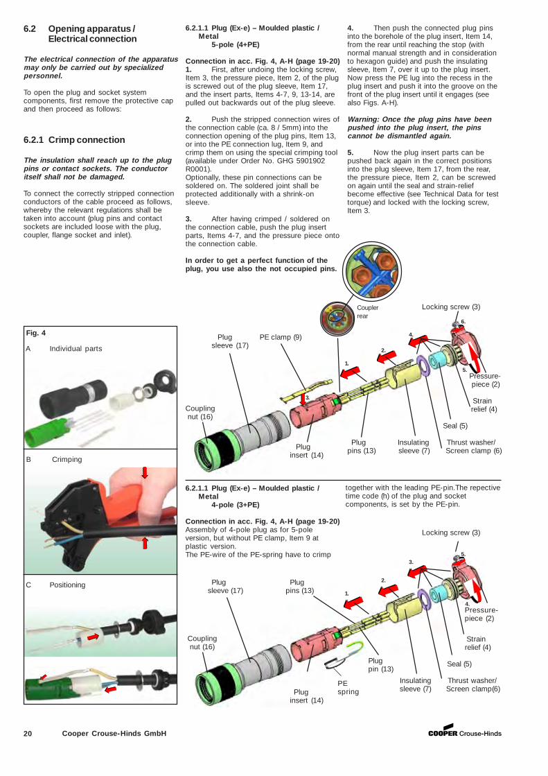
6.2.1.1 Plug (Ex-e) – Moulded plastic /Metal
5-pole (4+PE)
Connection in acc. Fig. 4, A-H (page 19-20)1. First, after undoing the locking screw,Item 3, the pressure piece, Item 2, of the plugis screwed out of the plug sleeve, Item 17,and the insert parts, Items 4-7, 9, 13-14, arepulled out backwards out of the plug sleeve.
2. Push the stripped connection wires ofthe connection cable (ca. 8 / 5mm) into theconnection opening of the plug pins, Item 13,or into the PE connection lug, Item 9, andcrimp them on using the special crimping tool(available under Order No. GHG 5901902R0001).Optionally, these pin connections can besoldered on. The soldered joint shall beprotected additionally with a shrink-onsleeve.
3. After having crimped / soldered onthe connection cable, push the plug insertparts, Items 4-7, and the pressure piece ontothe connection cable.
In order to get a perfect function of theplug, you use also the not occupied pins.
6.2 Opening apparatus /Electrical connection
The electrical connection of the apparatusmay only be carried out by specializedpersonnel.
To open the plug and socket systemcomponents, first remove the protective capand then proceed as follows:
4. Then push the connected plug pinsinto the borehole of the plug insert, Item 14,from the rear until reaching the stop (withnormal manual strength and in considerationto hexagon guide) and push the insulatingsleeve, Item 7, over it up to the plug insert.Now press the PE lug into the recess in theplug insert and push it into the groove on thefront of the plug insert until it engages (seealso Figs. A-H).
Warning: Once the plug pins have beenpushed into the plug insert, the pinscannot be dismantled again.
5. Now the plug insert parts can bepushed back again in the correct positionsinto the plug sleeve, Item 17, from the rear,the pressure piece, Item 2, can be screwedon again until the seal and strain-reliefbecome effective (see Technical Data for testtorque) and locked with the locking screw,Item 3.
3.
Coupling nut (16)
Plug PE clamp (9)sleeve (17)
1.
2.
6.
5.
Locking screw (3)
Pressure- piece (2)
Strain relief (4)
Seal (5)
Plug Insulating Thrust washer/pins (13) sleeve (7) Screen clamp (6) Plug
insert (14)
Fig. 4
A Individual parts
B Crimping
C Positioning
4.
6.2.1.1 Plug (Ex-e) – Moulded plastic /Metal
4-pole (3+PE)
Connection in acc. Fig. 4, A-H (page 19-20)Assembly of 4-pole plug as for 5-poleversion, but without PE clamp, Item 9 atplastic version.The PE-wire of the PE-spring have to crimp
Coupling nut (16)
Plug Plug sleeve (17) pins (13) 1.
2.
5.
4.
Strain relief (4)
Seal (5)
Insulating Thrust washer/sleeve (7) Screen clamp(6)
3.
Pluginsert (14)
6.2.1 Crimp connection
The insulation shall reach up to the plugpins or contact sockets. The conductoritself shall not be damaged.
To connect the correctly stripped connectionconductors of the cable proceed as follows,whereby the relevant regulations shall betaken into account (plug pins and contactsockets are included loose with the plug,coupler, flange socket and inlet).
Pressure-piece (2)
Locking screw (3)
Plugpin (13)
PEspring
together with the leading PE-pin.The repectivetime code (h) of the plug and socketcomponents, is set by the PE-pin.
Couplerrear
21Cooper Crouse-Hinds GmbH
Strain relief(4)
Seal (5) Thrust washer/ Screen clamp (6)
Contact Insulatingsockets (8) sleeve (7)
Locking screw (3)
3.
Coupler PE-clamp (9) sleeve (1)
1.
4. 6.
5.
Press-ure
piece (2)
Couplerinsert (10)
2.
Strain relief(4)
Seal (5) Thrust washer/ Screen clamp (6) Insulating
sleeve (7)
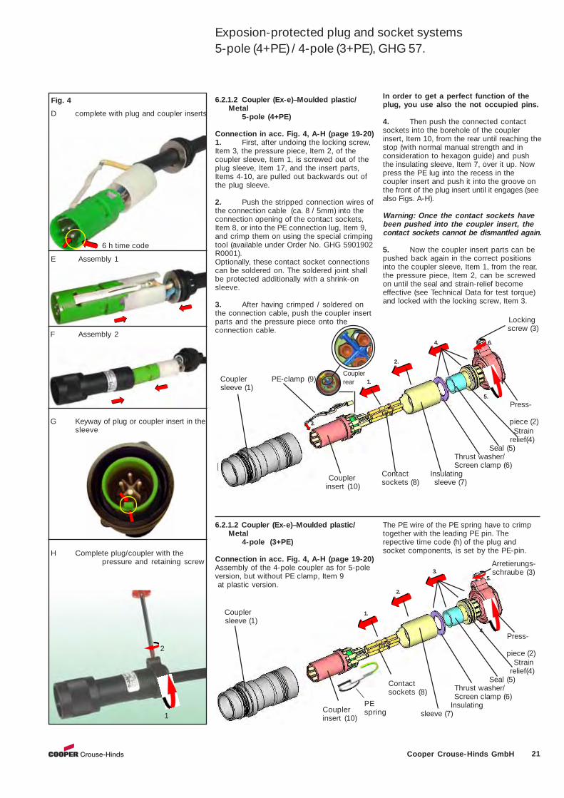
6.2.1.2 Coupler (Ex-e)–Moulded plastic/Metal
5-pole (4+PE)
Connection in acc. Fig. 4, A-H (page 19-20)1. First, after undoing the locking screw,Item 3, the pressure piece, Item 2, of thecoupler sleeve, Item 1, is screwed out of theplug sleeve, Item 17, and the insert parts,Items 4-10, are pulled out backwards out ofthe plug sleeve.
2. Push the stripped connection wires ofthe connection cable (ca. 8 / 5mm) into theconnection opening of the contact sockets,Item 8, or into the PE connection lug, Item 9,and crimp them on using the special crimpingtool (available under Order No. GHG 5901902R0001).Optionally, these contact socket connectionscan be soldered on. The soldered joint shallbe protected additionally with a shrink-onsleeve.
3. After having crimped / soldered onthe connection cable, push the coupler insertparts and the pressure piece onto theconnection cable.
In order to get a perfect function of theplug, you use also the not occupied pins.
4. Then push the connected contactsockets into the borehole of the couplerinsert, Item 10, from the rear until reaching thestop (with normal manual strength and inconsideration to hexagon guide) and pushthe insulating sleeve, Item 7, over it up. Nowpress the PE lug into the recess in thecoupler insert and push it into the groove onthe front of the plug insert until it engages (seealso Figs. A-H).
Warning: Once the contact sockets havebeen pushed into the coupler insert, thecontact sockets cannot be dismantled again.
5. Now the coupler insert parts can bepushed back again in the correct positionsinto the coupler sleeve, Item 1, from the rear,the pressure piece, Item 2, can be screwedon until the seal and strain-relief becomeeffective (see Technical Data for test torque)and locked with the locking screw, Item 3.
D complete with plug and coupler inserts
E Assembly 1
6.2.1.2 Coupler (Ex-e)–Moulded plastic/Metal
4-pole (3+PE)
Connection in acc. Fig. 4, A-H (page 19-20)Assembly of the 4-pole coupler as for 5-poleversion, but without PE clamp, Item 9 at plastic version.
Arretierungs- schraube (3)
Coupler sleeve (1)
1.
2.
3.5.
4. Press-
ure piece (2)
Couplerinsert (10)
Fig. 4
F Assembly 2
G Keyway of plug or coupler insert in thesleeve
H Complete plug/coupler with thepressure and retaining screw
2
1
6 h time code
Exposion-protected plug and socket systems5-pole (4+PE) / 4-pole (3+PE), GHG 57.
Couplerrear
Contactsockets (8)
PEspring
The PE wire of the PE spring have to crimptogether with the leading PE pin. Therepective time code (h) of the plug andsocket components, is set by the PE-pin.
22 Cooper Crouse-Hinds GmbH
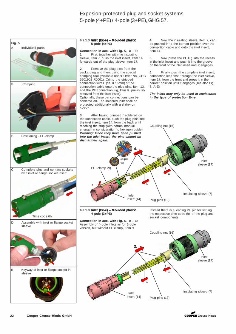
6.2.1.3 Inlet (Ex-e) – Moulded plasticnlet (Ex-e) – Moulded plasticnlet (Ex-e) – Moulded plasticnlet (Ex-e) – Moulded plasticnlet (Ex-e) – Moulded plastic5-pole (4+PE)
Connection in acc. with Fig. 5, A - E:1. First, together with the insulatingsleeve, Item 7, push the inlet insert, Item 14,forwards out of the plug sleeve, Item 17.
2. Remove the plug pins from thepacka-ging and then, using the specialcrimping tool (available under Order No. GHG5901902 R0001). Crimp the strippedconnection wires (ca. 8 / 5mm) of theconnection cable onto the plug pins, Item 13,and the PE connection lug, Item 9, (previouslyremoved from the inlet insert).Optionally, these pin connections can besoldered on. The soldered joint shall beprotected additionally with a shrink-onsleeve.
3. After having crimped / soldered onthe connection cable, push the plug pins intothe inlet insert, Item 14, from the back untilreaching the stop (with normal manualstrength in consideration to hexagon guide).Warning: Once they have been pushedinto the inlet insert, the pins cannot bedismantled again.
4. Now the insulating sleeve, Item 7, canbe pushed in to the correct position over theconnection cable and onto the inlet insert,Item 14.
5. Now press the PE lug into the recessin the inlet insert and push it into the grooveon the front of the inlet insert until it engages.
6. Finally, push the complete inlet insert,connection lead first, through the inlet sleeve,Item 17, from the front and press it in thecorrect position until it engages (see also Fig.5, A-E).
The inlets may only be used in enclosuresin the type of protection Ex-e.
2.
1.
4.
3.
Plug pins (13)
PE- clamp (9)
Inlet insert (14)
Insulating sleeve (7)
Coupling nut (16)
Inlet sleeve (17)
Fig. 5 A Individuell parts
B Positioning - PE-clamp
C Complete pins and contact socketswith inlet or flange socket insert
D Assemble with inlet or flange socketsleeve
E Keyway of inlet or flange socket insleeve
B Crimping
2.
1.
3.
Plug pins (13) Inlet insert (14)
Insulating sleeve (7)
Coupling nut (16)
Inlet sleeve (17)
6.2.1.3 Inlet (Ex-e) – Moulded plasticnlet (Ex-e) – Moulded plasticnlet (Ex-e) – Moulded plasticnlet (Ex-e) – Moulded plasticnlet (Ex-e) – Moulded plastic4-pole (3+PE)
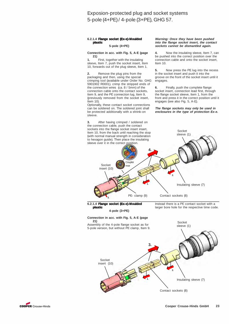
Connection in acc. with Fig. 5, A - E:Assembly of 4-pole inlets as for 5-poleversion, but without PE clamp, Item 9.
Instead there is a leading PE pin for settingthe respective time code (h) of the plug andsocket components. Time code 6h
Exposion-protected plug and socket systems5-pole (4+PE) / 4-pole (3+PE), GHG 57.
Couplerrear
23Cooper Crouse-Hinds GmbH
2.
1.
4.
3.
6.2.1.4 Flange socket (Ex-e)-MouldedFlange socket (Ex-e)-MouldedFlange socket (Ex-e)-MouldedFlange socket (Ex-e)-MouldedFlange socket (Ex-e)-Mouldedplasticplasticplasticplasticplastic
5-pole (4+PE)
Connection in acc. with Fig. 5, A-E (page21)
1. First, together with the insulatingsleeve, Item 7, push the socket insert, Item10, forwards out of the plug sleeve, Item 1.
2. Remove the plug pins from thepackaging and then, using the specialcrimping tool (available under Order No. GHG5901902 R0001). crimp the stripped ends ofthe connection wires (ca. 8 / 5mm) of theconnection cable onto the contact sockets,Item 9, and the PE connection lug, Item 9,(previously removed from the socket insert,Item 10).Optionally, these contact socket connectionscan be soldered on. The soldered joint shallbe protected additionally with a shrink-onsleeve.
3. After having crimped / soldered onthe connection cable, push the contactsockets into the flange socket insert insert,Item 10, from the back until reaching the stop(with normal manual strength in considerationto hexagon guide). Then place the insulatingsleeve over it in the correct position.
Warning: Once they have been pushedinto the flange socket insert, the contactsockets cannot be dismantled again.
4. Now the insulating sleeve, Item 7, canbe pushed into the correct position over theconnection cable and onto the socket insert,Item 10.
5. Now press the PE lug into the recessin the socket insert and push it into thegroove on the front of the socket insert until itengages.
6. Finally, push the complete flangesocket insert, connection lead first, throughthe flange socket sleeve, Item 1, from thefront and press it in the correct position until itengages (see also Fig. 5, A-E).
The flange sockets may only be used inenclosures in the type of protection Ex-e.
Socket insert (10)
PE- clamp (9) Contact sockets (8)
Insulating sleeve (7)
Socketsleeve (1)
2.
1.
3.
Socketinsert (10)
Contact sockets (8)
Insulating sleeve (7)
Socketsleeve (1)
6.2.1.4 Flange socket (Ex-e)-MouldedFlange socket (Ex-e)-MouldedFlange socket (Ex-e)-MouldedFlange socket (Ex-e)-MouldedFlange socket (Ex-e)-Mouldedplasticplasticplasticplasticplastic
4-pole (3+PE)
Connection in acc. with Fig. 5, A-E (page21)
Assembly of the 4-pole flange socket as for5-pole version, but without PE clamp, Item 9.
Instead there is a PE contact socket with alarger bore hole for the respective time code.
Exposion-protected plug and socket systems5-pole (4+PE) / 4-pole (3+PE), GHG 57.
Couplerrear
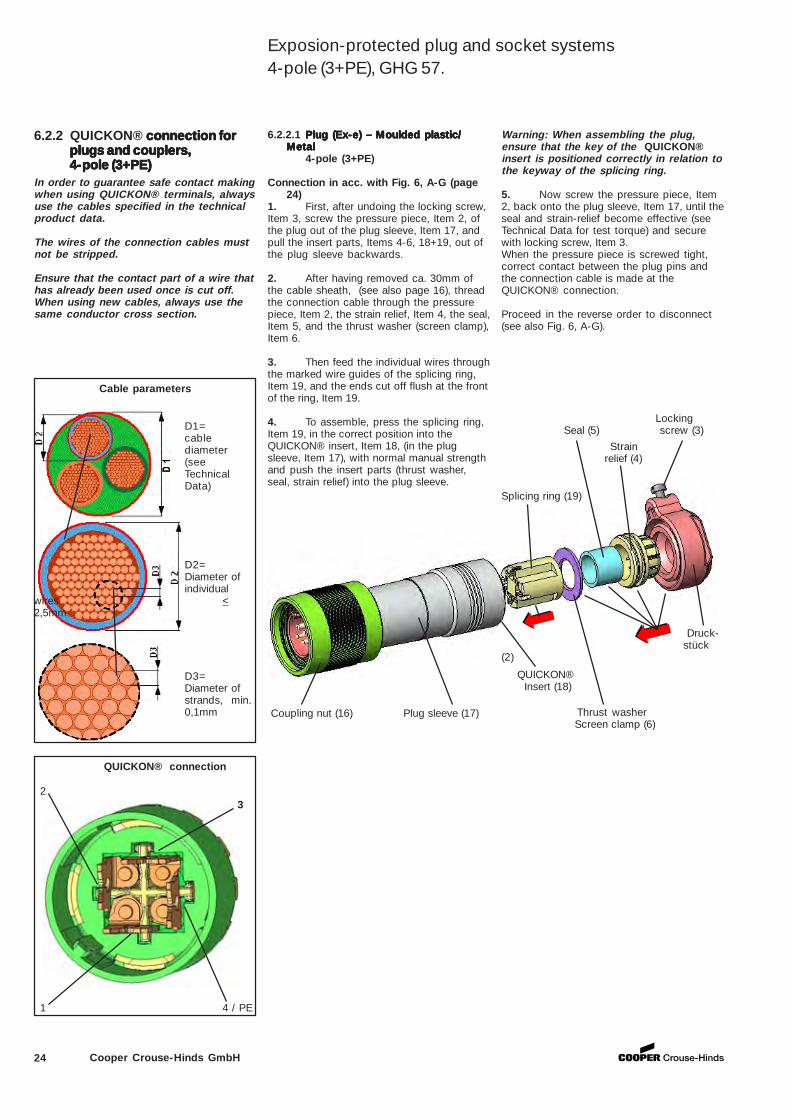
24 Cooper Crouse-Hinds GmbH
6.2.2 QUICKON® connection forconnection forconnection forconnection forconnection forplugs and couplers,plugs and couplers,plugs and couplers,plugs and couplers,plugs and couplers,4-pole (3+PE)4-pole (3+PE)4-pole (3+PE)4-pole (3+PE)4-pole (3+PE)
In order to guarantee safe contact makingwhen using QUICKON® terminals, alwaysuse the cables specified in the technicalproduct data.
The wires of the connection cables mustnot be stripped.
Ensure that the contact part of a wire thathas already been used once is cut off.When using new cables, always use thesame conductor cross section.
Cable parameters
D1=cablediameter(seeTechnicalData)
D2=Diameter ofindividual
wires <2,5mm
D3=Diameter ofstrands, min.0,1mm
QUICKON® connection
6.2.2.1 Plug (Ex-e) – Moulded plastic/Plug (Ex-e) – Moulded plastic/Plug (Ex-e) – Moulded plastic/Plug (Ex-e) – Moulded plastic/Plug (Ex-e) – Moulded plastic/MetalMetalMetalMetalMetal
4-pole (3+PE)
Connection in acc. with Fig. 6, A-G (page24)
1. First, after undoing the locking screw,Item 3, screw the pressure piece, Item 2, ofthe plug out of the plug sleeve, Item 17, andpull the insert parts, Items 4-6, 18+19, out ofthe plug sleeve backwards.
2. After having removed ca. 30mm ofthe cable sheath, (see also page 16), threadthe connection cable through the pressurepiece, Item 2, the strain relief, Item 4, the seal,Item 5, and the thrust washer (screen clamp),Item 6.
3. Then feed the individual wires throughthe marked wire guides of the splicing ring,Item 19, and the ends cut off flush at the frontof the ring, Item 19.
4. To assemble, press the splicing ring,Item 19, in the correct position into theQUICKON® insert, Item 18, (in the plugsleeve, Item 17), with normal manual strengthand push the insert parts (thrust washer,seal, strain relief) into the plug sleeve.
Coupling nut (16) Plug sleeve (17)
QUICKON® Insert (18)
Thrust washer Screen clamp (6)
Splicing ring (19)
Druck- stück
(2)
Locking Seal (5) screw (3)
Warning: When assembling the plug,ensure that the key of the QUICKON®insert is positioned correctly in relation tothe keyway of the splicing ring.
5. Now screw the pressure piece, Item2, back onto the plug sleeve, Item 17, until theseal and strain-relief become effective (seeTechnical Data for test torque) and securewith locking screw, Item 3.When the pressure piece is screwed tight,correct contact between the plug pins andthe connection cable is made at theQUICKON® connection.
Proceed in the reverse order to disconnect(see also Fig. 6, A-G).
2
1 4 / PE
3
Exposion-protected plug and socket systems4-pole (3+PE), GHG 57.
Strain relief (4)
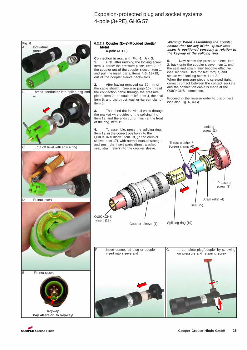
25Cooper Crouse-Hinds GmbH
Coupler sleeve (1)
Pressure screw (2)
Lockingscrew (3)
QUICKON® Insert (18)
6.2.2.2 Coupler (Ex-e)-Moulded plastic/Coupler (Ex-e)-Moulded plastic/Coupler (Ex-e)-Moulded plastic/Coupler (Ex-e)-Moulded plastic/Coupler (Ex-e)-Moulded plastic/MetalMetalMetalMetalMetal
4-pole (3+PE)
Connection in acc. with Fig. 6, A - G:1. First, after undoing the locking screw,Item 3, screw the pressure piece, Item 2, ofthe coupler out of the coupler sleeve, Item 1,and pull the insert parts, Items 4-6, 18+19,out of the coupler sleeve backwards.
2. After having removed ca. 30 mm ofthe cable sheath, (see also page 16), threadthe connection cable through the pressurepiece, Item 2, the strain relief, Item 4, the seal,Item 5, and the thrust washer (screen clamp),Item 6.
3. Then feed the individual wires throughthe marked wire guides of the splicing ring,Item 19, and the ends cut off flush at the frontof the ring, Item 19.
4. To assemble, press the splicing ring,Item 19, in the correct position into theQUICKON® insert, Item 18, (in the couplersleeve, Item 17), with normal manual strengthand push the insert parts (thrust washer,seal, strain relief) into the coupler sleeve.
Warning: When assembling the coupler,ensure that the key of the QUICKON®insert is positioned correctly in relation tothe keyway of the splicing ring.
5. Now screw the pressure piece, Item2, back onto the coupler sleeve, Item 1, untilthe seal and strain-relief become effective(see Technical Data for test torque) andsecure with locking screw, Item 3.When the pressure piece is screwed tight,correct contact between the contact socketsand the connection cable is made at theQUICKON® connection.
Proceed in the reverse order to disconnect(see also Fig. 6, A-G).
Fig. 6
B Thread conductor into splice ring and…
A Individualparts
D Fit into insert
F Insert connected plug or couplerinsert into sleeve and …
Keyway
Splicing ring (19)
Seal (5)
Strain relief (4)
Thrust washer / Screen clamp (6)
G … complete plug/coupler by screwingon pressure and retaining screw
2
1
E Fit into sleeve
Pay attention to keyway!
C ... cut off level with splice ring
Exposion-protected plug and socket systems4-pole (3+PE), GHG 57.
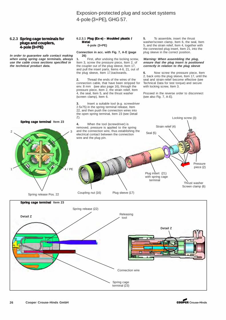
26 Cooper Crouse-Hinds GmbH
6.2.3 Spring cage terminals forSpring cage terminals forSpring cage terminals forSpring cage terminals forSpring cage terminals forplugs and couplers,plugs and couplers,plugs and couplers,plugs and couplers,plugs and couplers,4-pole (3+PE)4-pole (3+PE)4-pole (3+PE)4-pole (3+PE)4-pole (3+PE)
In order to guarantee safe contact makingwhen using spring cage terminals, alwaysuse the cable cross sections specified inthe technical product data.
Detail Z
Spring cage terminalSpring cage terminalSpring cage terminalSpring cage terminalSpring cage terminal Item 23
Detail Z
Spring cage terminal (23)
Spring cage terminalSpring cage terminalSpring cage terminalSpring cage terminalSpring cage terminal Item 23
1 4 / PE
Spring release Pos. 22 Coupling nut (16) Plug sleeve (17)
Plug insert (21) with spring cage terminal
Thrust washer Screen clamp (6)
Pressure piece (2)
Locking screw (3)
Releasing tool
Connection wire
6.2.3.1 Plug (Ex-e) - Moulded plastic /Plug (Ex-e) - Moulded plastic /Plug (Ex-e) - Moulded plastic /Plug (Ex-e) - Moulded plastic /Plug (Ex-e) - Moulded plastic /MetalMetalMetalMetalMetal
4-pole (3+PE)
Connection in acc. with Fig. 7, A-E (page26)
1. First, after undoing the locking screw,Item 3, screw the pressure piece, Item 2, ofthe coupler out of the plug sleeve, Item 17,and pull the insert parts, Items 4-6, 21, out ofthe plug sleeve, Item 17,backwards.
2. Thread the ends of the wires of theconnection cable, that have been stripped forenv. 8 mm (see also page 16), through thepressure piece, Item 2, the strain relief, Item4, the seal, Item 5, and the thrust washer(screen clamp), Item 6.
3. Insert a suitable tool (e.g. screwdriver2.5x75) in the spring terminal release, Item22, and then push the connection wires intothe open spring terminal, Item 23 (see DetailZ).
4. When the tool (screwdriver) isremoved, pressure is applied to the springand the connection wire, thus establishing theelectrical contact between the connectionwire and the plug pin.
5. To assemble, insert the thrustwasher/screen clamp, Item 6, the seal, Item5, and the strain relief, Item 4, together withthe connected plug insert, Item 21, into theplug sleeve in the correct position.
Warning: When assembling the plug,ensure that the plug insert is positionedcorrectly in relation to the plug sleeve
6. Now screw the pressure piece, Item2, back onto the plug sleeve, Item 17, until theseal and strain-relief become effective (seeTechnical Data for test torque) and securewith locking screw, Item 3.
Proceed in the reverse order to disconnect(see also Fig. 7, A-E).
Seal (5)
Spring release (22)
Strain relief (4)
2 3
Exposion-protected plug and socket systems4-pole (3+PE), GHG 57.
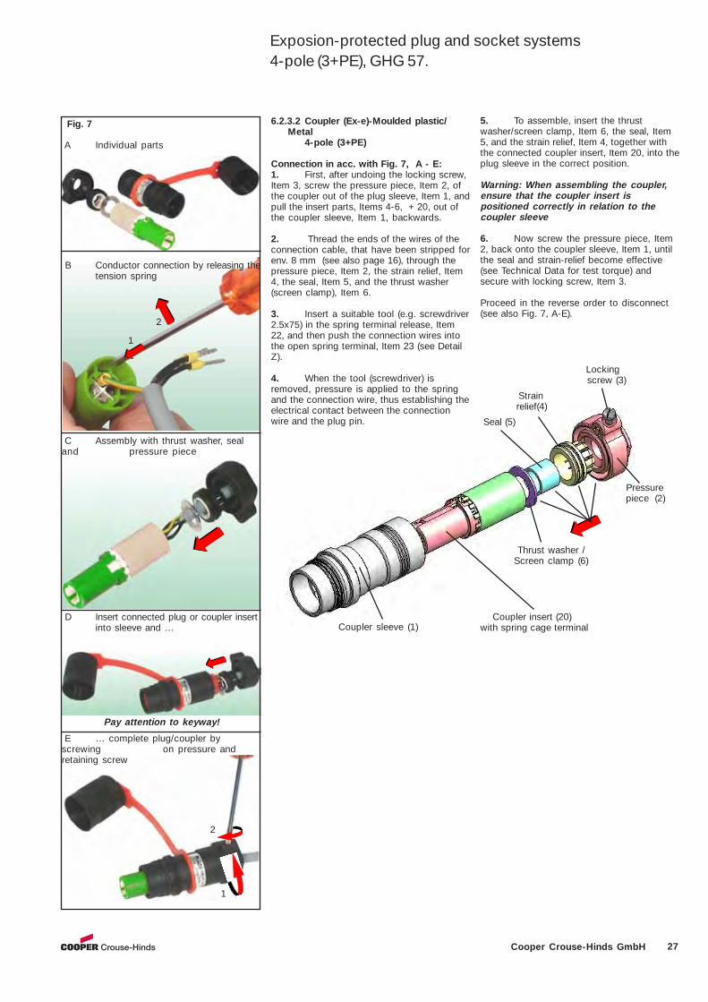
27Cooper Crouse-Hinds GmbH
Coupler insert (20)with spring cage terminal
Thrust washer /Screen clamp (6)
Pressure piece (2)
Locking screw (3)
Seal (5)
Strain relief(4)
Coupler sleeve (1)
6.2.3.2 Coupler (Ex-e)-Moulded plastic/Metal
4-pole (3+PE)
Connection in acc. with Fig. 7, A - E:1. First, after undoing the locking screw,Item 3, screw the pressure piece, Item 2, ofthe coupler out of the plug sleeve, Item 1, andpull the insert parts, Items 4-6, + 20, out ofthe coupler sleeve, Item 1, backwards.
2. Thread the ends of the wires of theconnection cable, that have been stripped forenv. 8 mm (see also page 16), through thepressure piece, Item 2, the strain relief, Item4, the seal, Item 5, and the thrust washer(screen clamp), Item 6.
3. Insert a suitable tool (e.g. screwdriver2.5x75) in the spring terminal release, Item22, and then push the connection wires intothe open spring terminal, Item 23 (see DetailZ).
4. When the tool (screwdriver) isremoved, pressure is applied to the springand the connection wire, thus establishing theelectrical contact between the connectionwire and the plug pin.
5. To assemble, insert the thrustwasher/screen clamp, Item 6, the seal, Item5, and the strain relief, Item 4, together withthe connected coupler insert, Item 20, into theplug sleeve in the correct position.
Warning: When assembling the coupler,ensure that the coupler insert ispositioned correctly in relation to thecoupler sleeve
6. Now screw the pressure piece, Item2, back onto the coupler sleeve, Item 1, untilthe seal and strain-relief become effective(see Technical Data for test torque) andsecure with locking screw, Item 3.
Proceed in the reverse order to disconnect(see also Fig. 7, A-E).
Fig. 7
B Conductor connection by releasing thetension spring
A Individual parts
C Assembly with thrust washer, sealand pressure piece
2
1
D Insert connected plug or coupler insertinto sleeve and …
E … complete plug/coupler byscrewing on pressure andretaining screw
Pay attention to keyway!
2
1
Exposion-protected plug and socket systems4-pole (3+PE), GHG 57.
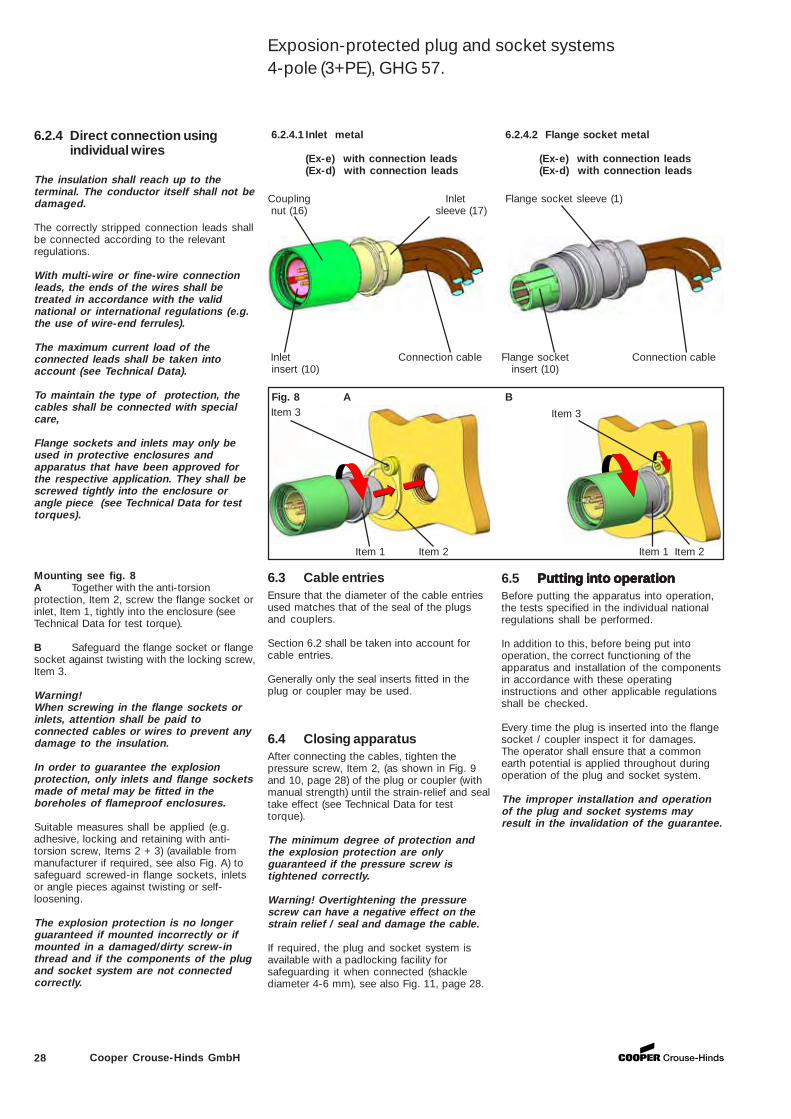
28 Cooper Crouse-Hinds GmbH
6.3 Cable entriesEnsure that the diameter of the cable entriesused matches that of the seal of the plugsand couplers.
Section 6.2 shall be taken into account forcable entries.
Generally only the seal inserts fitted in theplug or coupler may be used.
6.5 Putting into operationPutting into operationPutting into operationPutting into operationPutting into operationBefore putting the apparatus into operation,the tests specified in the individual nationalregulations shall be performed.
In addition to this, before being put intooperation, the correct functioning of theapparatus and installation of the componentsin accordance with these operatinginstructions and other applicable regulationsshall be checked.
Every time the plug is inserted into the flangesocket / coupler inspect it for damages.The operator shall ensure that a commonearth potential is applied throughout duringoperation of the plug and socket system.
The improper installation and operationof the plug and socket systems mayresult in the invalidation of the guarantee.
6.2.4.2 Flange socket metal
(Ex-e) with connection leads(Ex-d) with connection leads
6.2.4.1 Inlet metal
(Ex-e) with connection leads(Ex-d) with connection leads
Item 3
Item 1 Item 2 Item 1 Item 2
Coupling Inlet nut (16) sleeve (17)
Flange socket sleeve (1)
Flange socket Connection cable insert (10)
Inlet Connection cable insert (10)
Fig. 8 A Item 3
6.2.4 Direct connection usingindividual wires
The insulation shall reach up to theterminal. The conductor itself shall not bedamaged.
The correctly stripped connection leads shallbe connected according to the relevantregulations.
With multi-wire or fine-wire connectionleads, the ends of the wires shall betreated in accordance with the validnational or international regulations (e.g.the use of wire-end ferrules).
The maximum current load of theconnected leads shall be taken intoaccount (see Technical Data).
To maintain the type of protection, thecables shall be connected with specialcare,
Flange sockets and inlets may only beused in protective enclosures andapparatus that have been approved forthe respective application. They shall bescrewed tightly into the enclosure orangle piece (see Technical Data for testtorques).
B
Mounting see fig. 8A Together with the anti-torsionprotection, Item 2, screw the flange socket orinlet, Item 1, tightly into the enclosure (seeTechnical Data for test torque).
B Safeguard the flange socket or flangesocket against twisting with the locking screw,Item 3.
Warning!When screwing in the flange sockets orinlets, attention shall be paid toconnected cables or wires to prevent anydamage to the insulation.
In order to guarantee the explosionprotection, only inlets and flange socketsmade of metal may be fitted in theboreholes of flameproof enclosures.
Suitable measures shall be applied (e.g.adhesive, locking and retaining with anti-torsion screw, Items 2 + 3) (available frommanufacturer if required, see also Fig. A) tosafeguard screwed-in flange sockets, inletsor angle pieces against twisting or self-loosening.
The explosion protection is no longerguaranteed if mounted incorrectly or ifmounted in a damaged/dirty screw-inthread and if the components of the plugand socket system are not connectedcorrectly.
6.4 Closing apparatusAfter connecting the cables, tighten thepressure screw, Item 2, (as shown in Fig. 9and 10, page 28) of the plug or coupler (withmanual strength) until the strain-relief and sealtake effect (see Technical Data for testtorque).
The minimum degree of protection andthe explosion protection are onlyguaranteed if the pressure screw istightened correctly.
Warning! Overtightening the pressurescrew can have a negative effect on thestrain relief / seal and damage the cable.
If required, the plug and socket system isavailable with a padlocking facility forsafeguarding it when connected (shacklediameter 4-6 mm), see also Fig. 11, page 28.
Exposion-protected plug and socket systems4-pole (3+PE), GHG 57.
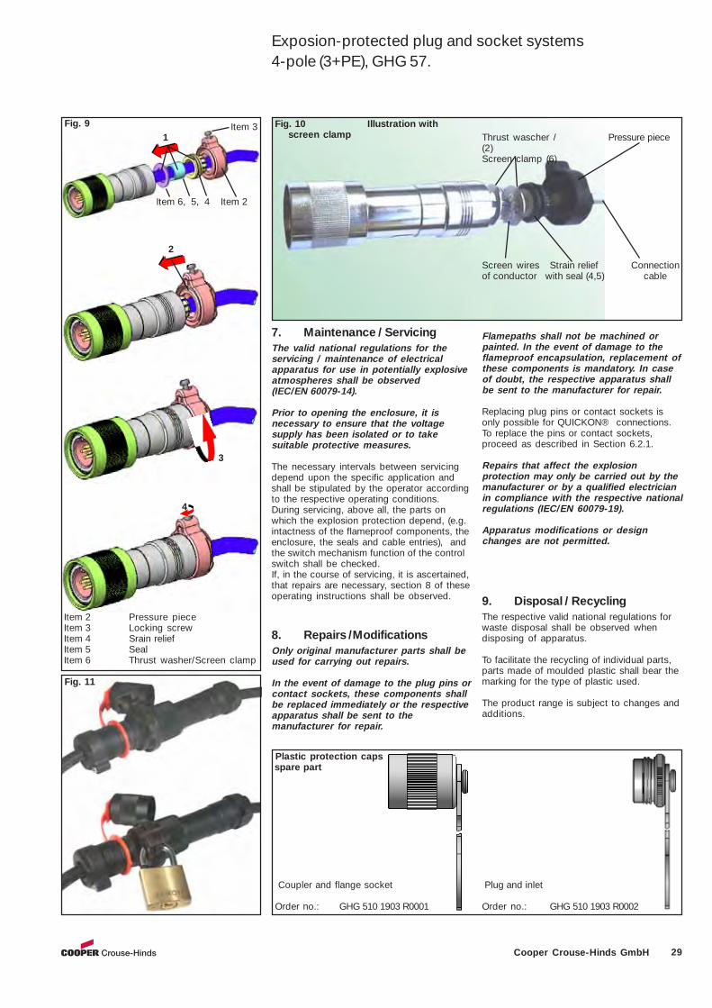
29Cooper Crouse-Hinds GmbH
9. Disposal / RecyclingThe respective valid national regulations forwaste disposal shall be observed whendisposing of apparatus.
To facilitate the recycling of individual parts,parts made of moulded plastic shall bear themarking for the type of plastic used.
The product range is subject to changes andadditions.
Flamepaths shall not be machined orpainted. In the event of damage to theflameproof encapsulation, replacement ofthese components is mandatory. In caseof doubt, the respective apparatus shallbe sent to the manufacturer for repair.
Replacing plug pins or contact sockets isonly possible for QUICKON® connections.To replace the pins or contact sockets,proceed as described in Section 6.2.1.
Repairs that affect the explosionprotection may only be carried out by themanufacturer or by a qualified electricianin compliance with the respective nationalregulations (IEC/EN 60079-19).
Apparatus modifications or designchanges are not permitted.
Fig. 9
2
3
4
Item 6, 5, 4 Item 2
Item 3
Item 2 Pressure piece Item 3 Locking screw Item 4 Srain relief Item 5 Seal Item 6 Thrust washer/Screen clamp
1
Coupler and flange socket
Order no.: GHG 510 1903 R0001
Plastic protection caps spare part
Fig. 11
7. Maintenance / ServicingThe valid national regulations for theservicing / maintenance of electricalapparatus for use in potentially explosiveatmospheres shall be observed(IEC/EN 60079-14).
Prior to opening the enclosure, it isnecessary to ensure that the voltagesupply has been isolated or to takesuitable protective measures.
The necessary intervals between servicingdepend upon the specific application andshall be stipulated by the operator accordingto the respective operating conditions.During servicing, above all, the parts onwhich the explosion protection depend, (e.g.intactness of the flameproof components, theenclosure, the seals and cable entries), andthe switch mechanism function of the controlswitch shall be checked.If, in the course of servicing, it is ascertained,that repairs are necessary, section 8 of theseoperating instructions shall be observed.
Fig. 10 Illustration withscreen clamp Thrust wascher / Pressure piece
(2)Screen clamp (6)
Screen wires Strain relief Connectionof conductor with seal (4,5) cable
8. Repairs /ModificationsOnly original manufacturer parts shall beused for carrying out repairs.
In the event of damage to the plug pins orcontact sockets, these components shallbe replaced immediately or the respectiveapparatus shall be sent to themanufacturer for repair.
Plug and inlet
Order no.: GHG 510 1903 R0002
Exposion-protected plug and socket systems4-pole (3+PE), GHG 57.
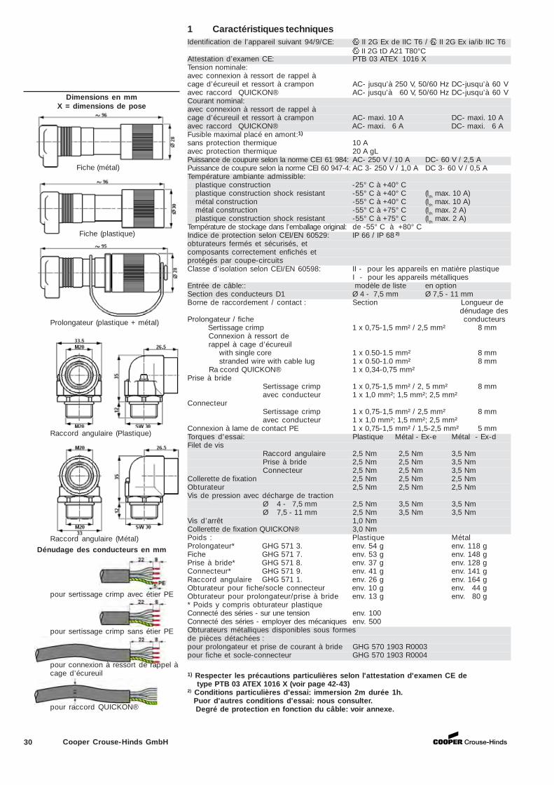
30 Cooper Crouse-Hinds GmbH
1 Caractéristiques techniquesIdentification de l’appareil suivant 94/9/CE: II 2G Ex de IIC T6 / II 2G Ex ia/ib IIC T6
II 2G tD A21 T80°CAttestation d’examen CE: PTB 03 ATEX 1016 XTension nominale:avec connexion à ressort de rappel àcage d’écureuil et ressort à crampon AC- jusqu’à 250 V, 50/60 Hz DC-jusqu’à 60 Vavec raccord QUICKON® AC- jusqu’à 60 V, 50/60 Hz DC-jusqu’à 60 VCourant nominal:avec connexion à ressort de rappel àcage d’écureuil et ressort à crampon AC- maxi. 10 A DC- maxi. 10 Aavec raccord QUICKON® AC- maxi. 6 A DC- maxi. 6 AFusible maximal placé en amont:1)
sans protection thermique 10 Aavec protection thermique 20 A gLPuissance de coupure selon la norme CEI 61 984: AC- 250 V / 10 A DC- 60 V / 2,5 APuissance de coupure selon la norme CEI 60 947-4: AC 3- 250 V / 1,0 A DC 3- 60 V / 0,5 ATempérature ambiante admissible:
plastique construction -25° C à +40° Cplastique construction shock resistant -55° C à +40° C (Ith max. 10 A)métal construction -55° C à +40° C (Ith max. 10 A)métal construction -55° C à +75° C (Ith max. 2 A)plastique construction shock resistant -55° C à +75° C (Ith max. 2 A)
Température de stockage dans l’emballage original: de -55° C à +80° CIndice de protection selon CEI/EN 60529: IP 66 / IP 68 2)
obturateurs fermés et sécurisés, etcomposants correctement enfichés etprotégés par coupe-circuitsClasse d’isolation selon CEI/EN 60598: II - pour les appareils en matière plastique
I - pour les appareils métalliquesEntrée de câble:: modèle de liste en optionSection des conducteurs D1 Ø 4 - 7,5 mm Ø 7,5 - 11 mmBorne de raccordement / contact : Section Longueur de
dénudage desProlongateur / fiche conducteurs Sertissage crimp 1 x 0,75-1,5 mm² / 2,5 mm² 8 mm
Connexion à ressort derappel à cage d’écureuil
with single core 1 x 0.50-1.5 mm² 8 mmstranded wire with cable lug 1 x 0.50-1.0 mm² 8 mm
Ra ccord QUICKON® 1 x 0,34-0,75 mm²Prise à bride
Sertissage crimp 1 x 0,75-1,5 mm² / 2, 5 mm² 8 mmavec conducteur 1 x 1,0 mm²; 1,5 mm²; 2,5 mm²
ConnecteurSertissage crimp 1 x 0,75-1,5 mm² / 2,5 mm² 8 mmavec conducteur 1 x 1,0 mm²; 1,5 mm²; 2,5 mm²
Connexion à lame de contact PE 1 x 0,75-1,5 mm² / 1,5-2,5 mm² 5 mmTorques d'essai: Plastique Métal - Ex-e Métal - Ex-dFilet de vis
Raccord angulaire 2,5 Nm 2,5 Nm 3,5 NmPrise à bride 2,5 Nm 2,5 Nm 3,5 NmConnecteur 2,5 Nm 2,5 Nm 3,5 Nm
Collerette de fixation 2,5 Nm 2,5 Nm 2,5 NmObturateur 2,5 Nm 2,5 Nm 2,5 NmVis de pression avec décharge de traction
Ø 4 - 7,5 mm 2,5 Nm 3,5 Nm 3,5 NmØ 7,5 - 11 mm 2,5 Nm 3,5 Nm 3,5 Nm
Vis d’arrêt 1,0 NmCollerette de fixation QUICKON® 3,0 NmPoids : Plastique MétalProlongateur* GHG 571 3. env. 54 g env. 118 gFiche GHG 571 7. env. 53 g env. 148 gPrise à bride* GHG 571 8. env. 37 g env. 128 gConnecteur* GHG 571 9. env. 41 g env. 141 gRaccord angulaire GHG 571 1. env. 26 g env. 164 gObturateur pour fiche/socle connecteur env. 10 g env. 44 gObturateur pour prolongateur/prise à bride env. 13 g env. 80 g* Poids y compris obturateur plastiqueConnecté des séries - sur une tension env. 100Connecté des séries - employer des mécaniques env. 500Obturateurs métalliques disponibles sous formesde pièces détachées :pour prolongateur et prise de courant à bride GHG 570 1903 R0003pour fiche et socle-connecteur GHG 570 1903 R0004
1) Respecter les précautions particulières selon l'attestation d'examen CE de type PTB 03 ATEX 1016 X (voir page 42-43)2) Conditions particulières d'essai: immersion 2m durée 1h. Puor d'autres conditions d'essai: nous consulter. Degré de protection en fonction du câble: voir annexe.
Dimensions en mmX = dimensions de pose
Dénudage des conducteurs en mm
pour sertissage crimp avec étier PE
pour connexion à ressort de rappel àcage d’écureuil
pour raccord QUICKON®
Prolongateur (plastique + métal)
Fiche (plastique)
Fiche (métal)
Raccord angulaire (Plastique)
Raccord angulaire (Métal)
pour sertissage crimp sans étier PE
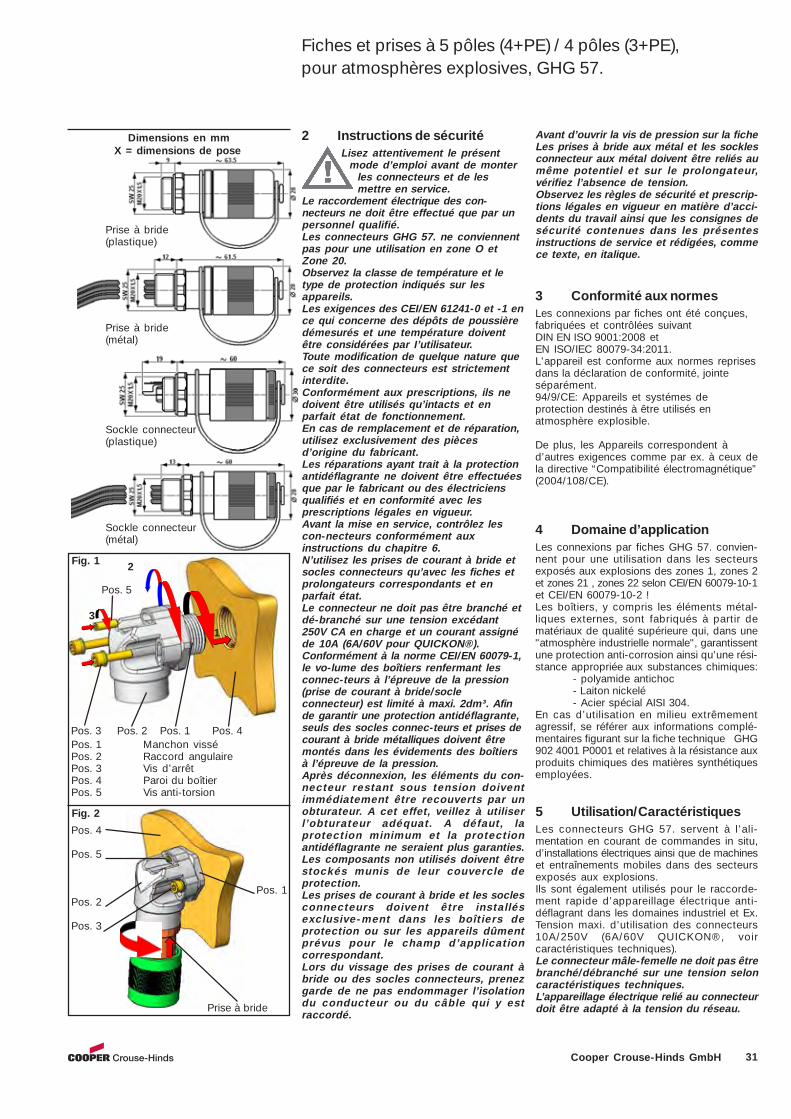
31Cooper Crouse-Hinds GmbH
2 Instructions de sécuritéLisez attentivement le présent
mode d’emploi avant de monterles connecteurs et de lesmettre en service.
Le raccordement électrique des con-necteurs ne doit être effectué que par unpersonnel qualifié.Les connecteurs GHG 57. ne conviennentpas pour une utilisation en zone O etZone 20.Observez la classe de température et letype de protection indiqués sur lesappareils.Les exigences des CEI/EN 61241-0 et -1 ence qui concerne des dépôts de poussièredémesurés et une température doiventêtre considérées par I’utilisateur.Toute modification de quelque nature quece soit des connecteurs est strictementinterdite.Conformément aux prescriptions, ils nedoivent être utilisés qu’intacts et enparfait état de fonctionnement.En cas de remplacement et de réparation,utilisez exclusivement des piècesd’origine du fabricant.Les réparations ayant trait à la protectionantidéflagrante ne doivent être effectuéesque par le fabricant ou des électriciensqualifiés et en conformité avec lesprescriptions légales en vigueur.Avant la mise en service, contrôlez lescon-necteurs conformément auxinstructions du chapitre 6.N’utilisez les prises de courant à bride etsocles connecteurs qu’avec les fiches etprolongateurs correspondants et enparfait état.Le connecteur ne doit pas être branché etdé-branché sur une tension excédant250V CA en charge et un courant assignéde 10A (6A/60V pour QUICKON®).Conformément à la norme CEI/EN 60079-1,le vo-lume des boîtiers renfermant lesconnec-teurs à l’épreuve de la pression(prise de courant à bride/socleconnecteur) est limité à maxi. 2dm³. Afinde garantir une protection antidéflagrante,seuls des socles connec-teurs et prises decourant à bride métalliques doivent êtremontés dans les évidements des boîtiersà l’épreuve de la pression.Après déconnexion, les éléments du con-necteur restant sous tension doiventimmédiatement être recouverts par unobturateur. A cet effet, veillez à utiliserl’obturateur adéquat. A défaut, laprotection minimum et la protectionantidéflagrante ne seraient plus garanties.Les composants non utilisés doivent êtrestockés munis de leur couvercle deprotection.Les prises de courant à bride et les soclesconnecteurs doivent être installésexclusive-ment dans les boîtiers deprotection ou sur les appareils dûmentprévus pour le champ d’applicationcorrespondant.Lors du vissage des prises de courant àbride ou des socles connecteurs, prenezgarde de ne pas endommager l’isolationdu conducteur ou du câble qui y estraccordé.
Dimensions en mmX = dimensions de pose
3 Conformité aux normesLes connexions par fiches ont été conçues,fabriquées et contrôlées suivantDIN EN ISO 9001:2008 etEN ISO/IEC 80079-34:2011.L'appareil est conforme aux normes reprisesdans la déclaration de conformité, jointeséparément.94/9/CE: Appareils et systémes deprotection destinés à être utilisés enatmosphère explosible.
De plus, les Appareils correspondent àd’autres exigences comme par ex. à ceux dela directive “Compatibilité électromagnétique”(2004/108/CE).
4 Domaine d’applicationLes connexions par fiches GHG 57. convien-nent pour une utilisation dans les secteursexposés aux explosions des zones 1, zones 2et zones 21 , zones 22 selon CEI/EN 60079-10-1et CEI/EN 60079-10-2 !Les boîtiers, y compris les éléments métal-liques externes, sont fabriqués à partir dematériaux de qualité supérieure qui, dans une"atmosphère industrielle normale", garantissentune protection anti-corrosion ainsi qu’une rési-stance appropriée aux substances chimiques:
- polyamide antichoc- Laiton nickelé- Acier spécial AISI 304.
En cas d’utilisation en milieu extrêmementagressif, se référer aux informations complé-mentaires figurant sur la fiche technique GHG902 4001 P0001 et relatives à la résistance auxproduits chimiques des matières synthétiquesemployées.
5 Utilisation/CaractéristiquesLes connecteurs GHG 57. servent à l’ali-mentation en courant de commandes in situ,d’installations électriques ainsi que de machineset entraînements mobiles dans des secteursexposés aux explosions.Ils sont également utilisés pour le raccorde-ment rapide d’appareillage électrique anti-déflagrant dans les domaines industriel et Ex.Tension maxi. d’utilisation des connecteurs10A/250V (6A/60V QUICKON®, voircaractéristiques techniques).Le connecteur mâle-femelle ne doit pas êtrebranché/débranché sur une tension seloncaractéristiques techniques.L’appareillage électrique relié au connecteurdoit être adapté à la tension du réseau.
3
2
1
Pos. 3 Pos. 2 Pos. 1 Pos. 4 Pos. 1 Manchon vissé Pos. 2 Raccord angulaire Pos. 3 Vis d’arrêt Pos. 4 Paroi du boîtier Pos. 5 Vis anti-torsion
Pos. 4
Pos. 5
Pos. 1 Pos. 2
Pos. 3
Prise à bride
Fig. 2
Pos. 5
Sockle connecteur(plastique)
Sockle connecteur(métal)
Prise à bride(métal)
Prise à bride(plastique)
Fig. 1
Avant d’ouvrir la vis de pression sur la ficheLes prises à bride aux métal et les socklesconnecteur aux métal doivent être reliés aumême potentiel et sur le prolongateur,vérifiez l’absence de tension.Observez les règles de sécurité et prescrip-tions légales en vigueur en matière d’acci-dents du travail ainsi que les consignes desécurité contenues dans les présentesinstructions de service et rédigées, commece texte, en italique.
Fiches et prises à 5 pôles (4+PE) / 4 pôles (3+PE),pour atmosphères explosives, GHG 57.
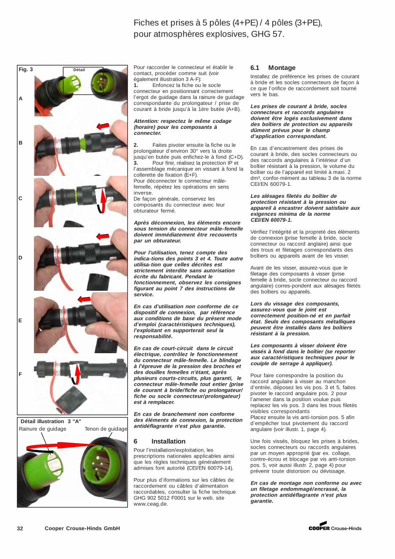
32 Cooper Crouse-Hinds GmbH
6.1 MontageInstallez de préférence les prises de courantà bride et les socles connecteurs de façon àce que l’orifice de raccordement soit tournévers le bas.
Les prises de courant à bride, soclesconnecteurs et raccords angulairesdoivent être logés exclusivement dansdes boîtiers de protection ou appareilsdûment prévus pour le champd’application correspondant.
En cas d’encastrement des prises decourant à bride, des socles connecteurs oudes raccords angulaires à l’intérieur d’unboîtier résistant à la pression, le volume duboîtier ou de l’appareil est limité à maxi. 2dm³, confor-mément au tableau 3 de la normeCEI/EN 60079-1.
Les alésages filetés du boîtier deprotection résistant à la pression ouappareil à encastrer doivent satisfaire auxexigences minima de la normeCEI/EN 60079-1.
Vérifiez l’intégrité et la propreté des élémentsde connexion (prise femelle à bride, socleconnecteur ou raccord anglaire) ainsi quedes trous et filetages correspondants desboîtiers ou appareils avant de les visser.
Avant de les visser, assurez-vous que lefiletage des composants à visser (prisefemelle à bride, socle connecteur ou raccordangulaire) corres-pondent aux alésages filetésdes boîtiers ou appareils.
Lors du vissage des composants,assurez-vous que le joint estcorrectement position-né et en parfaitétat. Seuls des composants métalliquespeuvent être installés dans les boîtiersrésistant à la pression.
Les composants à visser doivent êtrevissés à fond dans le boîtier (se reporteraux caractéristiques techniques pour lecouiple de serrage à appliquer).
Pour faire correspondre la position duraccord angulaire à visser au manchond’entrée, déposez les vis pos. 3 et 5, faitespivoter le raccord angulaire pos. 2 pourl’amener dans la position voulue puisreplacez les vis pos. 3 dans les trous filetésvisibles correspondantsPlacez ensuite la vis anti-torsion pos. 5 afind’empêcher tout pivotement du raccordangulaire (voir illustr. 1, page 4).
Une fois vissés, bloquez les prises à brides,socles connecteurs ou raccords angulairespar un moyen approprié (par ex. collage,contre-écrou et blocage par vis anti-torsionpos. 5, voir aussi illustr. 2, page 4) pourprévenir toute distorsion ou dévissage.
En cas de montage non conforme ou avecun filetage endommagé/encrassé, laprotection antidéflagrante n’est plusgarantie.
6 InstallationPour l’installation/exploitation, lesprescriptions nationales applicables ainsique les règles techniques généralementadmises font autorité (CEI/EN 60079-14).
Pour plus d’iformations sur les câbles deraccordement ou câbles d’alimentationraccordables, consulter la fiche techniqueGHG 902 5012 F0001 sur le web. sitewww.ceag.de.
Pour raccorder le connecteur et établir lecontact, procéder comme suit (voirégalement illustration 3 A-F):1. Enfoncez la fiche ou le socleconnecteur en positionnant correctementl’ergot de guidage dans la rainure de guidagecorrespondante du prolongateur / prise decourant à bride jusqu’à la 1ère butée (A+B).
Attention: respectez le même codage(horaire) pour les composants àconnecter.
2. Faites pivoter ensuite la fiche ou leprolongateur d’environ 30° vers la droitejusqu’en butée puis enfichez-le à fond (C+D).3. Pour finir, réalisez la protection IP etl’assemblage mécanique en vissant à fond lacollerette de fixation (E+F).Pour déconnecter le connecteur mâle-femelle, répétez les opérations en sensinverse.De façon générale, conservez lescomposants du connecteur avec leurobturateur fermé.
Après déconnexion, les éléments encoresous tension du connecteur mâle-femelledoivent immédiatement être recouvertspar un obturateur.
Pour l’utilisation, tenez compte desindica-tions des points 3 et 4. Toute autreutilisa-tion que celles décrites eststrictement interdite sans autorisationécrite du fabricant. Pendant lefonctionnement, observez les consignesfigurant au point 7 des instructions deservice.
En cas d’utilisation non conforme de cedispositif de connexion, par référenceaux conditions de base du présent moded’emploi (caractéristiques techniques),l’exploitant en supporterait seul laresponsabilité.
En cas de court-circuit dans le circuitélectrique, contrôlez le fonctionnementdu connecteur mâle-femelle. Le blindageà l’épreuve de la pression des broches etdes douilles femelles n’étant, aprèsplusieurs courts-circuits, plus garanti, leconnecteur mâle-femelle tout entier (prisede courant à bride/fiche ou prolongateur/fiche ou socle connecteur/prolongateur)est à remplacer.
En cas de branchement non conformedes éléments de connexion, la protectionantidéflagrante n’est plus garantie.
Fig. 3 Détail
Rainure de guidage Tenon de guidage
A
B
C
D
E
F
Détail illustration 3 "A"
Fiches et prises à 5 pôles (4+PE) / 4 pôles (3+PE),pour atmosphères explosives, GHG 57.
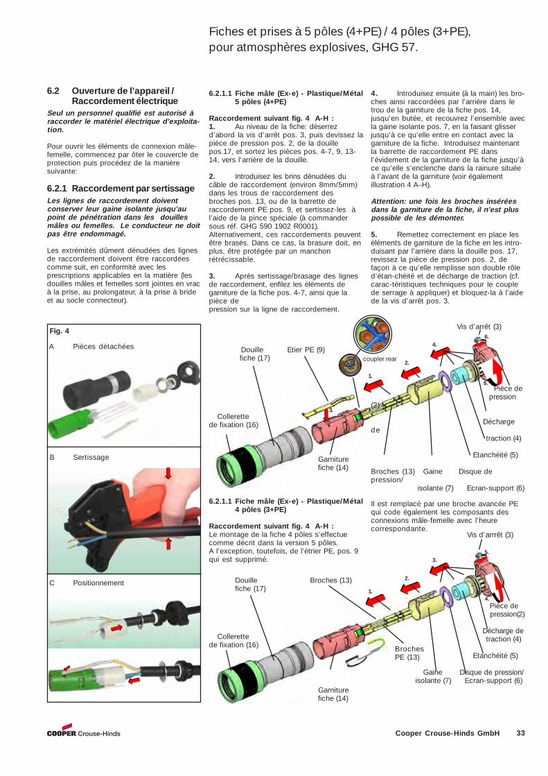
33Cooper Crouse-Hinds GmbH
3. Collerettede fixation (16)
Douille Etier PE (9) fiche (17)
1.
2.
6.
5.
Vis d’arrêt (3)
Piéce de pression
(2)
Déchargede
traction (4)
Etanchéité (5)
Broches (13) Gaine Disque depression/
isolante (7) Ecran-support (6)
Garniture fiche (14)
4.
6.2.1.1 Fiche mâle (Ex-e) - Plastique/Métal5 pôles (4+PE)
Raccordement suivant fig. 4 A-H :1. Au niveau de la fiche: déserrezd’abord la vis d’arrêt pos. 3, puis devissez lapièce de pression pos. 2, de la douillepos.17, et sortez les pièces pos. 4-7, 9, 13-14, vers l’arrière de la douille.
2. Introduisez les brins dénudées ducâble de raccordement (environ 8mm/5mm)dans les trous de raccordement desbroches pos. 13, ou de la barrette deraccordement PE pos. 9, et sertissez-les àl’aide de la pince spéciale (à commandersous réf. GHG 590 1902 R0001).Alternativement, ces raccordements peuventêtre brasés. Dans ce cas, la brasure doit, enplus, être protégée par un manchonrétrécissable.
3. Après sertissage/brasage des lignesde raccordement, enfilez les éléments degarniture de la fiche pos. 4-7, ainsi que lapièce depression sur la ligne de raccordement.
6.2 Ouverture de l’appareil /Raccordement électrique
Seul un personnel qualifié est autorisé àraccorder le matériel électrique d’exploita-tion.
Pour ouvrir les éléments de connexion mâle-femelle, commencez par ôter le couvercle deprotection puis procédez de la manièresuivante:
6.2.1 Raccordement par sertissageLes lignes de raccordement doiventconserver leur gaine isolante jusqu’aupoint de pénétration dans les douillesmâles ou femelles. Le conducteur ne doitpas être endommagé.
Les extrémités dûment dénudées des lignesde raccordement doivent être raccordéescomme suit, en conformité avec lesprescriptions applicables en la matière (lesdouilles mâles et femelles sont jointes en vracà la prise, au prolongateur, à la prise à brideet au socle connecteur).
4. Introduisez ensuite (à la main) les bro-ches ainsi raccordées par l’arrière dans letrou de la garniture de la fiche pos. 14,jusqu’en butée, et recouvrez l’ensemble avecla gaine isolante pos. 7, en la faisant glisserjusqu’à ce qu’elle entre en contact avec lagarniture de la fiche. Introduisez maintenantla barrette de raccordement PE dansl’évidement de la garniture de la fiche jusqu’àce qu’elle s’enclenche dans la rainure situéeà l’avant de la garniture (voir égalementillustration 4 A–H).
Attention: une fois les broches inséréesdans la garniture de la fiche, il n’est pluspossible de les démonter.
5. Remettez correctement en place leséléments de garniture de la fiche en les intro-duisant par l’arrière dans la douille pos. 17,revissez la pièce de pression pos. 2, defaçon à ce qu’elle remplisse son double rôled’étan-chéité et de décharge de traction (cf.carac-téristiques techniques pour le couplede serrage à appliquer) et bloquez-la à l’aidede la vis d’arrêt pos. 3.
Fig. 4
A Pièces détachées
B Sertissage
C Positionnement
6.2.1.1 Fiche mâle (Ex-e) - Plastique/Métal4 pôles (3+PE)
Raccordement suivant fig. 4 A-H :Le montage de la fiche 4 pôles s’effectuecomme décrit dans la version 5 pôles.A l’exception, toutefois, de l’étrier PE, pos. 9qui est supprimé.
Collerettede fixation (16)
Douille Broches (13)fiche (17) 1.
2.
5.
4.
Vis d’arrrêt (3)
Piéce de pression(2)
Décharge de traction (4)
Etanchéité (5)
Gaine Disque de pression/ isolante (7) Ecran-support (6)
3.
Il est remplacé par une broche avancée PEqui code également les composants desconnexions mâle-femelle avec l’heurecorrespondante.
Garniture fiche (14)
Fiches et prises à 5 pôles (4+PE) / 4 pôles (3+PE),pour atmosphères explosives, GHG 57.
coupler rear
BrochesPE (13)
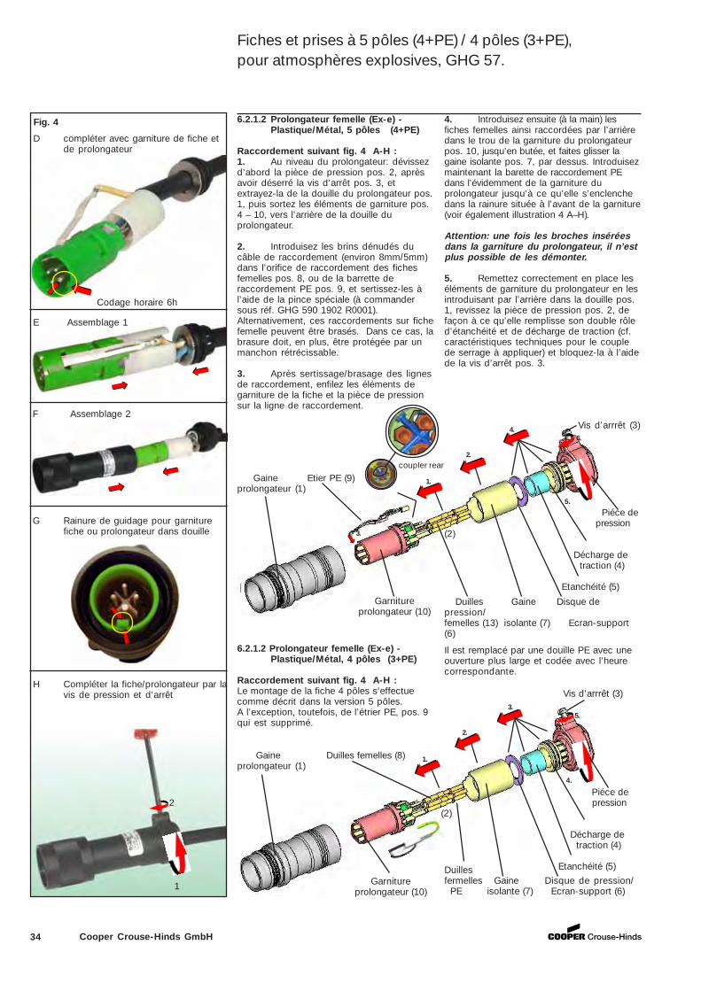
34 Cooper Crouse-Hinds GmbH
Vis d’arrrêt (3)
3.
Gaine Etier PE (9)prolongateur (1)
1.
2.
4.6.
5.
Piéce de pression
(2)
Décharge de traction (4)
Etanchéité (5)
Garniture prolongateur (10)
Duilles Gaine Disque depression/femelles (13) isolante (7) Ecran-support(6)
6.2.1.2 Prolongateur femelle (Ex-e) -Plastique/Métal, 5 pôles (4+PE)
Raccordement suivant fig. 4 A-H :1. Au niveau du prolongateur: dévissezd’abord la pièce de pression pos. 2, aprèsavoir déserré la vis d’arrêt pos. 3, etextrayez-la de la douille du prolongateur pos.1, puis sortez les éléments de garniture pos.4 – 10, vers l’arrière de la douille duprolongateur.
2. Introduisez les brins dénudés ducâble de raccordement (environ 8mm/5mm)dans l’orifice de raccordement des fichesfemelles pos. 8, ou de la barrette deraccordement PE pos. 9, et sertissez-les àl’aide de la pince spéciale (à commandersous réf. GHG 590 1902 R0001).Alternativement, ces raccordements sur fichefemelle peuvent être brasés. Dans ce cas, labrasure doit, en plus, être protégée par unmanchon rétrécissable.
3. Après sertissage/brasage des lignesde raccordement, enfilez les éléments degarniture de la fiche et la pièce de pressionsur la ligne de raccordement.
4. Introduisez ensuite (à la main) lesfiches femelles ainsi raccordées par l’arrièredans le trou de la garniture du prolongateurpos. 10, jusqu’en butée, et faites glisser lagaine isolante pos. 7, par dessus. Introduisezmaintenant la barette de raccordement PEdans l’évidemment de la garniture duprolongateur jusqu’à ce qu’elle s’enclenchedans la rainure située à l’avant de la garniture(voir également illustration 4 A–H).
Attention: une fois les broches inséréesdans la garniture du prolongateur, il n’estplus possible de les démonter.
5. Remettez correctement en place leséléments de garniture du prolongateur en lesintroduisant par l’arrière dans la douille pos.1, revissez la pièce de pression pos. 2, defaçon à ce qu’elle remplisse son double rôled’étanchéité et de décharge de traction (cf.caractéristiques techniques pour le couplede serrage à appliquer) et bloquez-la à l’aidede la vis d’arrêt pos. 3.
D compléter avec garniture de fiche etde prolongateur
E Assemblage 1
6.2.1.2 Prolongateur femelle (Ex-e) -Plastique/Métal, 4 pôles (3+PE)
Raccordement suivant fig. 4 A-H :Le montage de la fiche 4 pôles s’effectuecomme décrit dans la version 5 pôles.A l’exception, toutefois, de l’étrier PE, pos. 9qui est supprimé.
Vis d’arrrêt (3)
Gaine Duilles femelles (8)prolongateur (1)
1.
2.
3.5.
4.
Piéce de pression
(2)
Décharge de traction (4)
Etanchéité (5)
Garniture prolongateur (10)
Duillesfermelles Gaine Disque de pression/ PE isolante (7) Ecran-support (6)
Il est remplacé par une douille PE avec uneouverture plus large et codée avec l’heurecorrespondante.
Fig. 4
F Assemblage 2
G Rainure de guidage pour garniturefiche ou prolongateur dans douille
H Compléter la fiche/prolongateur par lavis de pression et d’arrêt
2
1
Codage horaire 6h
Fiches et prises à 5 pôles (4+PE) / 4 pôles (3+PE),pour atmosphères explosives, GHG 57.
coupler rear
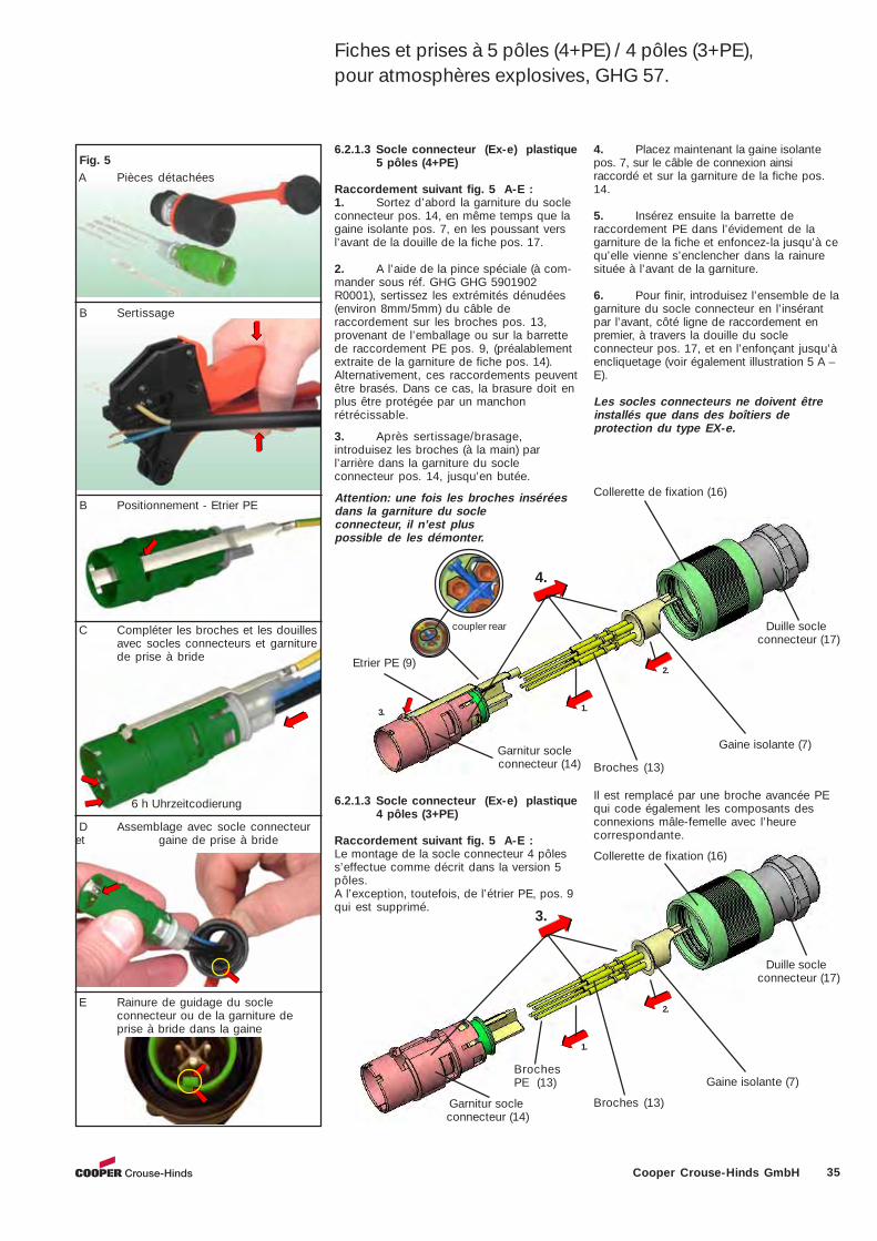
35Cooper Crouse-Hinds GmbH
2.
1.
4.
3.
Broches (13)
Etrier PE (9)
Garnitur socle connecteur (14)
Gaine isolante (7)
Collerette de fixation (16)
Duille socle connecteur (17)
6.2.1.3 Socle connecteur (Ex-e) plastique5 pôles (4+PE)
Raccordement suivant fig. 5 A-E :1. Sortez d’abord la garniture du socleconnecteur pos. 14, en même temps que lagaine isolante pos. 7, en les poussant versl’avant de la douille de la fiche pos. 17.
2. A l’aide de la pince spéciale (à com-mander sous réf. GHG GHG 5901902R0001), sertissez les extrémités dénudées(environ 8mm/5mm) du câble deraccordement sur les broches pos. 13,provenant de l’emballage ou sur la barrettede raccordement PE pos. 9, (préalablementextraite de la garniture de fiche pos. 14).Alternativement, ces raccordements peuventêtre brasés. Dans ce cas, la brasure doit enplus être protégée par un manchonrétrécissable.
3. Après sertissage/brasage,introduisez les broches (à la main) parl’arrière dans la garniture du socleconnecteur pos. 14, jusqu’en butée.
Attention: une fois les broches inséréesdans la garniture du socleconnecteur, il n’est pluspossible de les démonter.
4. Placez maintenant la gaine isolantepos. 7, sur le câble de connexion ainsiraccordé et sur la garniture de la fiche pos.14.
5. Insérez ensuite la barrette deraccordement PE dans l’évidement de lagarniture de la fiche et enfoncez-la jusqu’à cequ’elle vienne s’enclencher dans la rainuresituée à l’avant de la garniture.
6. Pour finir, introduisez l’ensemble de lagarniture du socle connecteur en l’insérantpar l’avant, côté ligne de raccordement enpremier, à travers la douille du socleconnecteur pos. 17, et en l’enfonçant jusqu’àencliquetage (voir également illustration 5 A –E).
Les socles connecteurs ne doivent êtreinstallés que dans des boîtiers deprotection du type EX-e.
Fig. 5 A Pièces détachées
B Positionnement - Etrier PE
C Compléter les broches et les douillesavec socles connecteurs et garniturede prise à bride
D Assemblage avec socle connecteuret gaine de prise à bride
E Rainure de guidage du socleconnecteur ou de la garniture deprise à bride dans la gaine
B Sertissage
2.
1.
3.
Broches (13) Garnitur socle connecteur (14)
Gaine isolante (7)
Collerette de fixation (16)
Duille socle connecteur (17)
6.2.1.3 Socle connecteur (Ex-e) plastique4 pôles (3+PE)
Raccordement suivant fig. 5 A-E :Le montage de la socle connecteur 4 pôless’effectue comme décrit dans la version 5pôles.A l’exception, toutefois, de l’étrier PE, pos. 9qui est supprimé.
Il est remplacé par une broche avancée PEqui code également les composants desconnexions mâle-femelle avec l’heurecorrespondante.
6 h Uhrzeitcodierung
Fiches et prises à 5 pôles (4+PE) / 4 pôles (3+PE),pour atmosphères explosives, GHG 57.
BrochesPE (13)
coupler rear
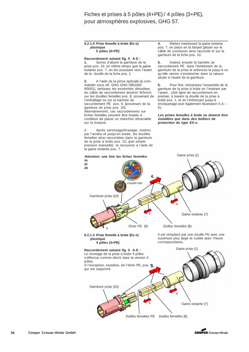
36 Cooper Crouse-Hinds GmbH
6.2.1.4 Prise femelle à bride (Ex-e)plastique
5 pôles (4+PE)
Raccordement suivant fig. 5 A-E :1. Sortez d’abord la garniture de laprise pos. 10, en même temps que la gaineisolante pos. 7, en les poussant vers l’avantde la douille de la fiche pos. 1.
2. A l’aide de la pince spéciale (à com-mander sous réf. GHG GHG 5901902R0001), sertissez les extrémités dénudéesdu câble de raccordement (environ 8/5mm)sur les douilles femelles pos. 8, provenant del’emballage ou sur la barrette deraccordement PE pos. 9, (provenant de lagarniture de prise pos. 10).Alternativement, ces raccordements surfiches femelles peuvent être brasés àcondition de placer un manchon rétractablesur la brasure.
3. Après sertissage/brasage, insérezpar l‘arrière et jusqu‘en butée, les douillesfemelles ainsi raccordées dans la garniturede la prise à bride pos. 10, (par simplepression manuelle) et recouvrez à l’aide dela gaine isolante pos. 7.
Attention: une fois les fiches femellesinsérées dans la garniture de la prise àbride, il n’est plus possible de lesdémonter.
4. Mettez maintenant la gaine isolantepos. 7, en place en la faisant glisser sur lecâble de connexion ainsi raccordé et sur lagarniture de la fiche pos. 10.
5. Insérez ensuite la barrette deraccordement PE dans l’évidement de lagarniture de la prise et enfoncez-la jusqu’à cequ’elle vienne s’enclencher dans la rainuresituée à l’avant de la garniture.
6. Pour finir, introduisez l’ensemble de lagarniture de la prise à bride en l’insérant parl’avant , côté ligne de raccordement enpremier, à travers la douille de la prise àbride pos. 1, et en l’enfonçant jusqu’àencliquetage (voir également illustration 5 A –E).
Les prises femelles à bride ne doivent êtreinstallées que dans des boîtiers deprotection du type EX-e.
2.
1.
3.
Garniture prise (10)
Duilles femelles (8)
Gaine isolante (7)
Gaine prise (1)
6.2.1.4 Prise femelle à bride (Ex-e)plastique
4 pôles (3+PE)
Raccordement suivant fig. 5 A-E :Le montage de la prise à bride 4 pôless’effectue comme décrit dans la version 5pôles.A l’exception, toutefois, de l’étrier PE, pos. 9qui est supprimé.
Il est remplacé par une douille PE avec uneouverture plus large et codée avec l’heurecorrespondante.
Fiches et prises à 5 pôles (4+PE) / 4 pôles (3+PE),pour atmosphères explosives, GHG 57.
Duilles femelles PE
2.
1.
4.
3.
Garniture prise (10)
Etrier PE (9) Duilles femelles (8)
Gaine isolante (7)
Gaine prise (1)
coupler rear
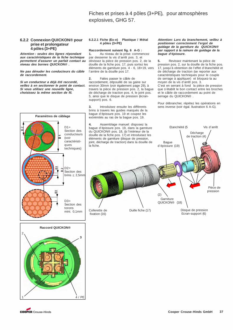
37Cooper Crouse-Hinds GmbH
6.2.2 Connexion QUICKON® pourprise et prolongateur4 pôles (3+PE)
Attention : seules des lignes répondantaux caractéristiques de la fiche techniquepermettent d’assurer un parfait contact auniveau des bornes QUICKON® .
Ne pas dénuder les conducteurs du câblede raccordement.
Si un conducteur a déjà été raccordé,veillez à en sectionner le point de contact.Si vous utilisez une nouvelle ligne,choisissez la même section de fil.
Paramètres de câblage
D1=Section desconducteurs(voircaractéristi-questechniques)
D2=Section desbrins < 2,5mm
D3=Section destoronsmini. 0,1mm
Raccord QUICKON®
6.2.2.1 Fiche (Ex-e) Plastique / Métal4 pôles (3+PE)
Raccordement suivant fig. 6 A-G :1. Au niveau de la prise: commencezpar desserrer la vis d’arrêt pos. 3, etdévissez la pièce de pression pos. 2, de ladouille de la fiche pos. 17, puis sortez leséléments de garniture pos. 4 - 6, 18+19, versl’arrière de la douille pos 17.
2. Faites passer le câble deraccordement, dépouillé de sa gaine surenviron 30mm (voir également page 29), àtravers la pièce de pression pos. 2, la baguede décharge de traction pos. 4, le joint pos.5, ainsi que le disque de pression (écran-support) pos. 6.
3. Introduisez ensuite les différentsbrins à travers les guides marqués de labague d’épissure pos. 19 et coupez lesextrémités au ras de la bague pos. 19.
4. Assemblage manuel: disposez labague d’épissure pos. 19, dans la garnituredu QUICKON® pos. 18, (à l’intérieur de ladouille de la fiche pos. 17) et introduisez leséléments de garniture (disque de pression,joint, décharge de traction) dans la douille dela fiche.
Collerette de Duille fiche (17) fixation (16)
GarnitureQUICKON® (18)
Disque de pression Ecran-support (6)
Bagued’épissure (19)
Pièce de pression
(2)
Etanchéité (5 Vis d’arrêt
Attention: Lors du branchement, veillez àpositionner correctement l’ergot deguidage de la garniture du QUICKON®par rapport à la rainure de guidage de labague d‘épissure.
5. Revissez maintenant la pièce depression pos. 2, sur la douille de la fiche pos.17, jusqu’à obtention de l’effet d’étanchéité etde décharge de traction (se reporter auxcaractéristiques techniques pour le couplede serrage à appliquer) et bloquez-la aumoyen de la vis d’arrêt pos. 3.C’est en serrant à fond la pièce de pressionque s’établit le bon contact entre les brocheset le câble de raccordement au point deserrage du QUICKON® .
Pour débrancher, répétez les opérations ensens inverse (voir égal. llustration 6 A-G).
2
1 4 / PE
3
Fiches et prises à 4 pôles (3+PE), pour atmosphèresexplosives, GHG 57.
Décharge de traction (4)
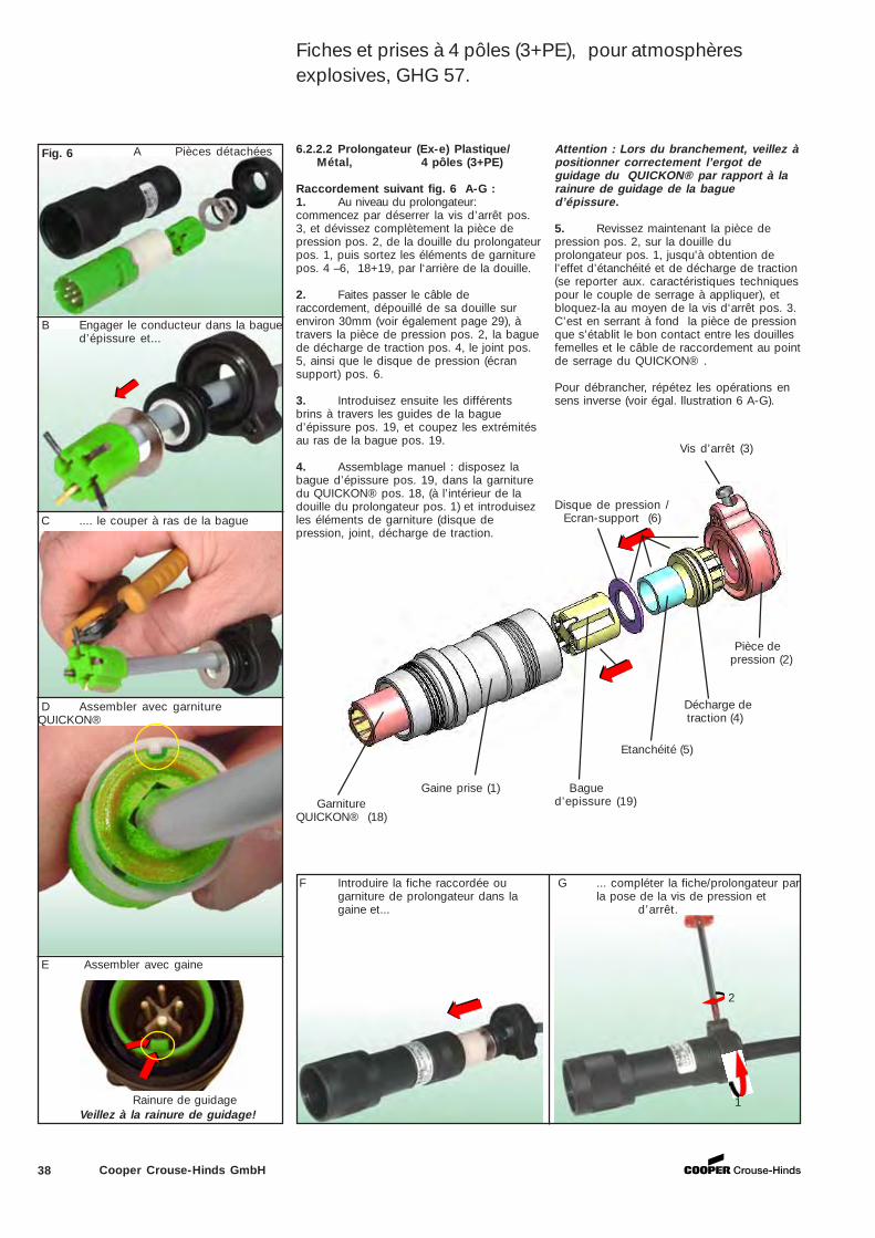
38 Cooper Crouse-Hinds GmbH
Gaine prise (1)
Pièce de pression (2)
Vis d’arrêt (3)
GarnitureQUICKON® (18)
6.2.2.2 Prolongateur (Ex-e) Plastique/Métal, 4 pôles (3+PE)
Raccordement suivant fig. 6 A-G :1. Au niveau du prolongateur:commencez par déserrer la vis d’arrêt pos.3, et dévissez complètement la pièce depression pos. 2, de la douille du prolongateurpos. 1, puis sortez les éléments de garniturepos. 4 –6, 18+19, par l‘arrière de la douille.
2. Faites passer le câble deraccordement, dépouillé de sa douille surenviron 30mm (voir également page 29), àtravers la pièce de pression pos. 2, la baguede décharge de traction pos. 4, le joint pos.5, ainsi que le disque de pression (écransupport) pos. 6.
3. Introduisez ensuite les différentsbrins à travers les guides de la bagued’épissure pos. 19, et coupez les extrémitésau ras de la bague pos. 19.
4. Assemblage manuel : disposez labague d’épissure pos. 19, dans la garnituredu QUICKON® pos. 18, (à l’intérieur de ladouille du prolongateur pos. 1) et introduisezles éléments de garniture (disque depression, joint, décharge de traction.
Attention : Lors du branchement, veillez àpositionner correctement l’ergot deguidage du QUICKON® par rapport à larainure de guidage de la bagued’épissure.
5. Revissez maintenant la pièce depression pos. 2, sur la douille duprolongateur pos. 1, jusqu’à obtention del’effet d’étanchéité et de décharge de traction(se reporter aux. caractéristiques techniquespour le couple de serrage à appliquer), etbloquez-la au moyen de la vis d‘arrêt pos. 3.C’est en serrant à fond la pièce de pressionque s’établit le bon contact entre les douillesfemelles et le câble de raccordement au pointde serrage du QUICKON® .
Pour débrancher, répétez les opérations ensens inverse (voir égal. llustration 6 A-G).
Fig. 6
B Engager le conducteur dans la bagued’épissure et...
A Pièces détachées
D Assembler avec garnitureQUICKON®
F Introduire la fiche raccordée ougarniture de prolongateur dans lagaine et...
Rainure de guidage
Bagued’epissure (19)
Etanchéité (5)
Décharge de traction (4)
Disque de pression / Ecran-support (6)
G ... compléter la fiche/prolongateur parla pose de la vis de pression et
d’arrêt.
2
1
E Assembler avec gaine
Veillez à la rainure de guidage!
C .... le couper à ras de la bague
Fiches et prises à 4 pôles (3+PE), pour atmosphèresexplosives, GHG 57.
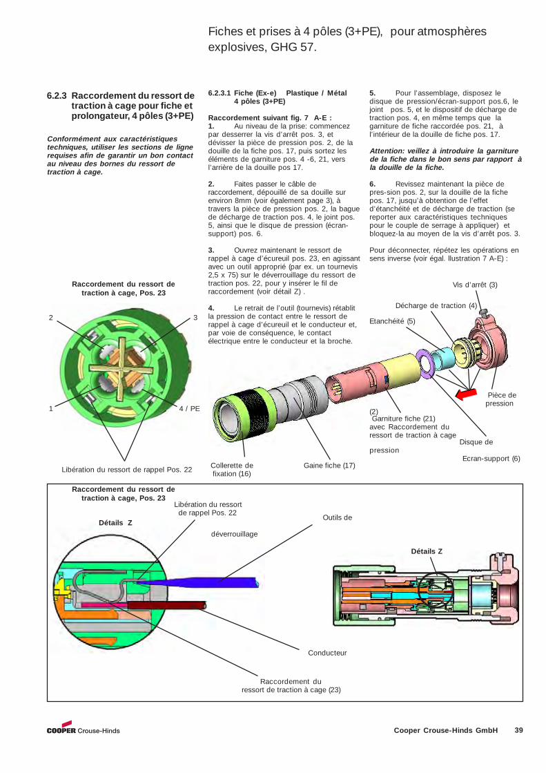
39Cooper Crouse-Hinds GmbH
6.2.3 Raccordement du ressort detraction à cage pour fiche etprolongateur, 4 pôles (3+PE)
Conformément aux caractéristiquestechniques, utiliser les sections de lignerequises afin de garantir un bon contactau niveau des bornes du ressort detraction à cage.
Détails Z
Raccordement du ressort detraction à cage, Pos. 23
Détails Z
Raccordement du ressort de traction à cage (23)
Raccordement du ressort detraction à cage, Pos. 23
1 4 / PE
Libération du ressort de rappel Pos. 22 Collerette de Gaine fiche (17) fixation (16)
Garniture fiche (21)avec Raccordement duressort de traction à cage
Disque depression
Ecran-support (6)
Pièce de pression
(2)
Vis d’arrêt (3)
Outils de
déverrouillage
Conducteur
6.2.3.1 Fiche (Ex-e) Plastique / Métal4 pôles (3+PE)
Raccordement suivant fig. 7 A-E :1. Au niveau de la prise: commencezpar desserrer la vis d’arrêt pos. 3, etdévisser la pièce de pression pos. 2, de ladouille de la fiche pos. 17, puis sortez leséléments de garniture pos. 4 -6, 21, versl’arrière de la douille pos 17.
2. Faites passer le câble deraccordement, dépouillé de sa douille surenviron 8mm (voir également page 3), àtravers la pièce de pression pos. 2, la baguede décharge de traction pos. 4, le joint pos.5, ainsi que le disque de pression (écran-support) pos. 6.
3. Ouvrez maintenant le ressort derappel à cage d’écureuil pos. 23, en agissantavec un outil approprié (par ex. un tournevis2,5 x 75) sur le déverrouillage du ressort detraction pos. 22, pour y insérer le fil deraccordement (voir détail Z) .
4. Le retrait de l’outil (tournevis) rétablitla pression de contact entre le ressort derappel à cage d’écureuil et le conducteur et,par voie de conséquence, le contactélectrique entre le conducteur et la broche.
5. Pour l’assemblage, disposez ledisque de pression/écran-support pos.6, lejoint pos. 5, et le dispositif de décharge detraction pos. 4, en même temps que lagarniture de fiche raccordée pos. 21, àl’intérieur de la douille de fiche pos. 17.
Attention: veillez à introduire la garniturede la fiche dans le bon sens par rapport àla douille de la fiche.
6. Revissez maintenant la pièce depres-sion pos. 2, sur la douille de la fichepos. 17, jusqu’à obtention de l’effetd’étanchéité et de décharge de traction (sereporter aux caractéristiques techniquespour le couple de serrage à appliquer) etbloquez-la au moyen de la vis d’arrêt pos. 3.
Pour déconnecter, répétez les opérations ensens inverse (voir égal. llustration 7 A-E) :
Etanchéité (5)
Libération du ressort de rappel Pos. 22
Décharge de traction (4)
2 3
Fiches et prises à 4 pôles (3+PE), pour atmosphèresexplosives, GHG 57.
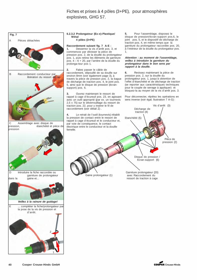
40 Cooper Crouse-Hinds GmbH
Garniture prolongateur (20) avec Raccordement du ressort de traction à cage
Disque de pression / Ecran-support (6)
Pièce depression (2)
Vis d’arrêt (3)
Etanchéité (5)
Décharge de traction (4)
Gaine prolongateur (1)
6.2.3.2 Prolongateur (Ex-e)-Plastique/Métal
4 pôles (3+PE)
Raccordement suivant fig. 7 A-E :1. Desserrez la vis d’arrêt pos. 3, etcommencez par dévisser la pièce depression pos. 2, de la douille du prolongateurpos. 1, puis retirez les éléments de garniturepos. 4 – 6 + 20, par l’arrière de la douille duprolonga-teur pos 1.
2. Faites passer le câble deraccordement, dépouillé de sa douille surenviron 8mm (voir également page 3), àtravers la pièce de pression pos. 2, la baguede décharge de traction pos. 4, le joint pos.5, ainsi que le disque de pression (écran-support) pos. 6.
3. Ouvrez maintenant le ressort derappel à cage d’écureuil pos. 23, en agissantavec un outil approprié (par ex. un tournevis2,5 x 75) sur le déverrouillage du ressort detraction pos. 22, pour y insérer le fil deraccordement (voir détail Z) .
4. Le retrait de l’outil (tournevis) rétablitla pression de contact entre le ressort derappel à cage d’écureuil et le conducteur et,par voie de conséquence, le contactélectrique entre le conducteur et la douillefemelle.
5. Pour l’assemblage, disposez ledisque de pression/écran-support pos.6, lejoint pos. 5, et le dispositif de décharge detraction pos. 4, en même temps que lagarniture du prolongateur raccordée pos. 20,à l’intérieur de la douille du prolongateur pos.1.
Attention : au moment de l’assemblage,veillez à introduire la garniture duprolongateur dans le bon sens parrapport à la douille.
6. Revissez maintenant la pièce depression pos. 2, sur la douille duprolongateur pos. 1, jusqu’à obtention del’effet d’étanchéité et de décharge de traction(se reporter aux caractéristiques techniquespour le couple de serrage à appliquer) etbloquez-la au moyen de la vis d’arrêt pos. 3.
Pour déconnecter, répétez les opérations ensens inverse (voir égal. llustration 7 A-G) :
Fig. 7
B Raccordement conducteur parlibération du ressort de rap
A Pièces détachées
C Assemblage avec disque depression, étanchéité et pièce depression
2
1
D Introduire la fiche raccordée ougarniture de prolongateur
dans la gaine et...
E ... compléter la fiche/prolongateur parla pose de la vis de pression et
d’arrêt.
Veillez à la rainure de guidage!
2
1
Fiches et prises à 4 pôles (3+PE), pour atmosphèresexplosives, GHG 57.
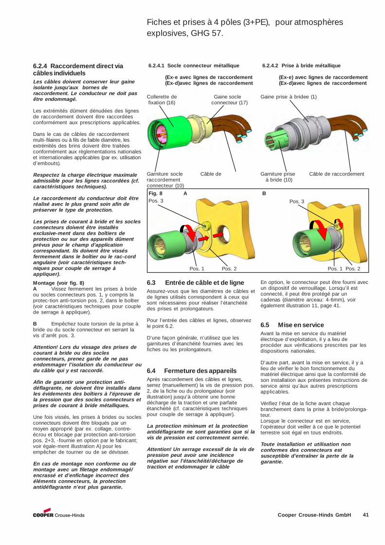
41Cooper Crouse-Hinds GmbH
6.3 Entrée de câble et de ligneAssurez-vous que les diamètres de câbles etde lignes utilisés correspondent à ceux quisont nécessaires pour réaliser l’étanchéitédes prises et prolongateurs.
Pour l’entrée des câbles et lignes, observezle point 6.2.
D’une façon générale, n’utilisez que lesgarnitures d’étanchéité fournies avec lesfiches ou les prolongateurs.
6.5 Mise en serviceAvant la mise en service du matérielélectrique d’exploitation, il y a lieu deprocéder aux vérifications prescrites par lesdispositions nationales.
D’autre part, avant la mise en service, il y alieu de vérifier le bon fonctionnement dumatériel électrique ainsi que la conformité deson installation aux présentes instructions deservice ainsi qu’àux autres prescriptionsapplicables.
Vérifiez l’état de la fiche avant chaquebranchement dans la prise à bride/prolonga-teur.Lorsque le connecteur est en service,l’opérateur doit veiller à ce que le potentielterrestre soit égal en tous endroits.
Toute installation et utilisation nonconformes des connecteurs estsusceptible d’entraîner la perte de lagarantie.
6.2.4.2 Prise à bride métallique
(Ex-e) avec lignes de raccordement(Ex-d)avec lignes de raccordement
6.2.4.1 Socle connecteur métallique
(Ex-e avec lignes de raccordement(Ex-d)avec lignes de raccordement
Pos. 3
Pos. 1 Pos. 2 Pos. 1 Pos. 2
Collerette de Gaine socle fixation (16) connecteur (17)
Gaine prise à bridee (1)
Garniture prise Câble de raccordement à bride (10)
Garniture socle Câble deraccordementconnecteur (10)
Fig. 8 A Pos. 3
6.2.4 Raccordement direct viacâbles individuelsLes câbles doivent conserver leur gaineisolante jusqu’aux bornes deraccordement. Le conducteur ne doit pasêtre endommagé.
Les extrémités dûment dénudées des lignesde raccordement doivent être raccordéesconformément aux prescriptions applicables.
Dans le cas de câbles de raccordementmulti-filaires ou à fils de faible diamètre, lesextrémités des brins doivent être traitéesconformément aux règlementations nationaleset internationales applicables (par ex. utilisationd’embouts).
Respectez la charge électrique maximaleadmissible pour les lignes raccordées (cf.caractéristiques techniques).
Le raccordement du conducteur doit êtreréalisé avec le plus grand soin afin depréserver le type de protection.
Les prises de courant à bride et les soclesconnecteurs doivent être installésexclusive-ment dans des boîtiers deprotection ou sur des appareils dûmentprévus pour le champ d’applicationcorrespondant. Ils doivent être vissésfermement dans le boîtier ou le rac-cordangulaire (voir caractéristiques tech-niques pour couple de serrage àappliquer).
B
Montage (voir fig. 8)A Vissez fermement les prises à brideou socles connecteurs pos. 1, y compris laprotec-tion anti-torsion pos. 2, dans le boîtier(voir caractéristiques techniques pour couplede serrage à appliquer).
B Empêchez toute torsion de la prise àbride ou du socle connecteur en serrant lavis d’arrêt pos. 3.
Attention! Lors du vissage des prises decourant à bride ou des soclesconnecteurs, prenez garde de ne pasendommager l’isolation du conducteur oudu câble qui y est raccordé.
Afin de garantir une protection anti-déflagrante, ne doivent être installés dansles évidements des boîtiers à l’épreuve dela pression que des socles connecteurs etprises de courant à bride métalliques.
Une fois vissés, les prises à brides ou soclesconnecteurs doivent être bloqués par unmoyen approprié (par ex. collage, contre-écrou et blocage par protection anti-torsionpos. 2+3, -fournie en option par le fabricant;voir égale-ment illustration A) pour lesempêcher de tourner ou de se dévisser.
En cas de montage non conforme ou demontage avec un filetage endommagé/encrassé et d’enfichage incorrect deséléments connecteurs, la protectionantidéflagrante n’est plus garantie.
6.4 Fermeture des appareilsAprès raccordement des câbles et lignes,serrez (manuellement) la vis de pression pos.2, de la fiche ou du prolongateur (voirillustration) jusqu’à obtenir une bonnedécharge de la traction et une parfaiteétanchéité (cf. caractéristiques techniquespour couple de serrage à appliquer).
La protection minimum et la protectionantidéflagrante ne sont garanties que si lavis de pression est correctement serrée.
Attention! Un serrage excessif de la vis depression peut avoir une incidencenégative sur l’étanchéité/décharge detraction et endommager le câble
En option, le connecteur peut être fourni avecun dispositif de verrouillage. Lorsqu’il estconnecté, il peut être protégé par uncadenas (diamètre arceau: 4-6mm), voirégalement illustration 11, page 41.
Fiches et prises à 4 pôles (3+PE), pour atmosphèresexplosives, GHG 57.
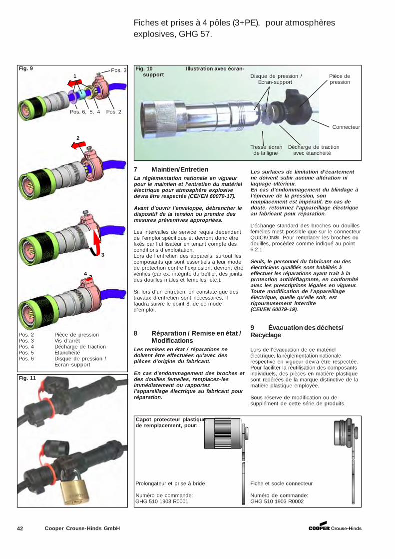
42 Cooper Crouse-Hinds GmbH
Les surfaces de limitation d’écartementne doivent subir aucune altération nilaquage ultérieur.En cas d’endommagement du blindage àl’épreuve de la pression, sonremplacement est impératif. En cas dedoute, retournez l’appareillage électriqueau fabricant pour réparation.
L’échange standard des broches ou douillesfemelles n’est possible que sur le connecteurQUICKON®. Pour remplacer les broches oudouilles, procédez comme indiqué au point6.2.1.
Seuls, le personnel du fabricant ou desélectriciens qualifiés sont habilités àeffectuer les réparations ayant trait à laprotection antidéflagrante, en conformitéavec les prescriptions légales en vigueur.Toute modification de l’appareillageélectrique, quelle qu’elle soit, estrigoureusement interdite(CEI/EN 60079-19).
Fig. 9
2
3
4
Pos. 6, 5, 4 Pos. 2
Pos. 3
Pos. 2 Pièce de pression Pos. 3 Vis d’arrêt Pos. 4 Décharge de traction Pos. 5 Etanchéité Pos. 6 Disque de pression /
Ecran-support
1
Prolongateur et prise à bride
Numéro de commande: GHG 510 1903 R0001
Capot protecteur plastique de remplacement, pour:
Fig. 11
7 Maintien/EntretienLa règlementation nationale en vigueurpour le maintien et l’entretien du matérielélectrique pour atmosphère explosivedevra être respectée (CEI/EN 60079-17).
Avant d’ouvrir l’enveloppe, débrancher ledispositif de la tension ou prendre desmesures préventives appropriées.
Les intervalles de service requis dépendentde l’emploi spécifique et devront donc êtrefixés par l’utilisateur en tenant compte desconditions d’exploitation.Lors de l’entretien des appareils, surtout lescomposants qui sont essentiels à leur modede protection contre l’explosion, devront êtrevérifiés (par ex. intégrité du boîtier, des joints,des douilles mâles et femelles, etc.).
Si, lors d’un entretien, on constate que destravaux d’entretien sont nécessaires, ilfaudra suivre le point 8, de ce moded’emploi.
Fig. 10 Illustration avec écran-support Disque de pression / Pièce de
Ecran-support pression
Tresse écran Décharge de traction de la ligne avec étanchéité
8 Réparation / Remise en état /Modifications
Les remises en état / réparations nedoivent être effectuées qu’avec despièces d’origine du fabricant.
En cas d’endommagement des broches etdes douilles femelles, remplacez-lesimmédiatement ou rapportezl’appareillage électrique au fabricant pourréparation.
Fiche et socle connecteur
Numéro de commande:GHG 510 1903 R0002
Fiches et prises à 4 pôles (3+PE), pour atmosphèresexplosives, GHG 57.
Connecteur
9 Évacuation des déchets/Recyclage
Lors de l’évacuation de ce matérielélectrique, la règlementation nationalerespective en vigueur devra être respectée.Pour faciliter la réutilisation des composantsindividuels, des pièces en matière plastiquesont repérées de la marque distinctive de lamatière plastique employée.
Sous réserve de modification ou desupplément de cette série de produits.

43Cooper Crouse-Hinds GmbH

Cooper Crouse-Hinds GmbHCooper Crouse-Hinds GmbHCooper Crouse-Hinds GmbHCooper Crouse-Hinds GmbHCooper Crouse-Hinds GmbH
Neuer Weg-Nord 49D 69412 Eberbach / GermanyFone 0049 (0) 6271 / 806 - 500Fax 0049 (0) 6271 / 806 - 476Internet: www.ceag.deE-Mail: [email protected] G
HG
570
700
1 P
0001
D/E
/F /
(E
)/A
ufla
ge 0
5.14
/Str