Agrément Technique Européen ETA-10/0241secbvba.be/frontend/files/userfiles/files/ETA...
58
Deutsches Institut für Bautechnik Anstalt des öffentlichen Rechts Kolonnenstr. 30 L 10829 Berlin Germany Tel.: +49(0)30 787 30 0 Fax: +49(0)30 787 30 320 E-mail: [email protected] Internet: www.dibt.de Mitglied der EOTA Membre de EOTA Agrément Technique Européen ETA-10/0241 Traduction française assurée par Finnforest – document original en Allemand Handelsbezeichnung Nom commercial LenoTec LenoTec - Leno Zulassungsinhaber Titulaire Finnforest Merk GmbH Industriestraße 2 86551 Aichach Zulassungsgegenstand und Verwendungszweck Massive plattenförmige Holzbauelemente zur Verwendung als tragende Teile in Bauwerken Type générique et utilisation prévue du produit de construction Panneaux de bois massif à utiliser comme éléments de structure de bâtiments Geltungsdauer: Validité : vom du 12 Août 2010 bis au 12 Août 2015 Herstellwerk Usine de fabrication Finnforest Merk GmbH Industriestraße 2 86551 Aichach DEUTSCHLAND Diese Zulassung umfasst Cet Agrément contient 19 Seiten einschließlich 5 Anhänge 19 pages incluant 5 annexes Europäische Organisation für Technische Zulassungen European Organisation for Technical Approvals
Transcript of Agrément Technique Européen ETA-10/0241secbvba.be/frontend/files/userfiles/files/ETA...
Deutsches Institut für BautechnikAnstalt des öffentlichen Rechts
Kolonnenstr. 30 L10829 BerlinGermany
Tel.: +49(0)30 787 30 0 Fax: +49(0)30 787 30 320 E-mail: [email protected]: www.dibt.de
Mitglied der EOTAMembre de EOTA
Agrément Technique Européen ETA-10/0241
Traduction française assurée par Finnforest – document original en Allemand
HandelsbezeichnungNom commercial
LenoTecLenoTec - Leno
ZulassungsinhaberTitulaire
Finnforest Merk GmbHIndustriestraße 2 86551 Aichach
Zulassungsgegenstandund Verwendungszweck
Massive plattenförmige Holzbauelemente zur Verwendung alstragende Teile in Bauwerken
Type générique et utilisation prévue du produit de construction
Panneaux de bois massif à utiliser comme éléments de structure debâtiments
Geltungsdauer:Validité :
vomdu
12 Août 2010
bisau
12 Août 2015
Herstellwerk Usine de fabrication
Finnforest Merk GmbHIndustriestraße 2 86551 Aichach DEUTSCHLAND
Diese Zulassung umfasstCet Agrément contient
19 Seiten einschließlich 5 Anhänge19 pages incluant 5 annexes
E u r o p ä i s c h e O r g a n i s a t i o n f ü r T e c h n i s c h e Z u l a s s u n g e n
E u r o p e a n O r g a n i s a t i o n f o r T e c h n i c a l A p p r o v a l s
Page 2 - Agrément Technique Européen ETA-10/0241, délivré le 12 Août 2010
I BASES JURIDIQUES ET CONDITIONS GENERALES
1 Le présent agrément technique européen est délivré par l'institut allemand des techniques de construction en conformité avec:
- La directive du Conseil 89/106/CEE1 du 21 décembre 1988 relative au rapprochement des dispositions législatives, réglementaires et administratives des Etats membres concernant les produites de construction, modifiée par la directive du Conseil 93/68/CEE2 du 22 juillet 1993 et la réglementation (CE) du Parlement et du Conseil Européen n°1882/20033 ;
- Gesetz über das In-Verkehr-Bringen von und den freien Warenverkehr mit Bauprodukten zur Umsetzung der Richtlinie 89/106/EWG des Rates vom 21. Dezember 1988 zur Angleichung der Rechts- und Verwaltungsvorschriften der Mitgliedstaaten über Bauprodukte und anderer Rechtsakte der Europäischen Gemeinschaften (Bauprodukten- gesetz - BauPG) vom 28. April 19984, as amended by law of 31 October 20065 ;
- Les règles communes de procédure relatives à la demande, la préparation et la délivrance d'Agréments Techniques Européens, définies dans l'annexe de la décision de la commission 94/23/CE6
2. L'institut allemand des techniques de construction est habilité à vérifier si les dispositions du présent agrément technique européen sont respectées. Cette vérification peut s'effectuer dans l'unité de production. Cependant, la conformité des produits liés à l'agrément technique européen et leur appropriation à l'usage prévu restent de la responsabilité du détenteur de cet agrément.
3. Le présent agrément technique européen ne doit pas être transmis à des fabricants ou leurs agents autres que ceux figurant en page 1, ni à des unités de fabrication autres que celles mentionnées en page 1 du présent agrément.
4. Le présent agrément technique européen peut être retiré par l'institut allemand des techniques de construction conformément à l'article 5(1) de la directive du Conseil 89/106/CEE.
5. Seule est autorisée la reproduction intégrale du présent agrément technique européen, y compris transmission par voie électronique. Cependant, une reproduction partielle peut être admise moyennant accord écrit de l'institut allemand des techniques de construction. Dans ce cas, la reproduction partielle doit être désignée comme telle. Les textes et dessins de brochures publicitaires ne doivent pas être en contradiction avec l'agrément technique européen, ni s'y référer de manière abusive.
6. L’agrément technique européen original est délivré par l'organisme d'agrément dans sa langue officielle. Cette version doit correspondre en totalité à la version diffusée au sein de l'EOTA. Les traductions dans d’autres langues doivent être désignées comme telles.
1 Journal officiel des communautés européennes n°L40, 11/02/1989, p. 12
2 Journal officiel des communautés européennes n°L220, 30/08/1993, p. 1
3 Journal officiel de l'Union européenne, n°L284, 31/10/2003, p. 1
4 Bundesgesetzblatt Teil I 2006, p.2407, 2416
5 Bundesgesetzblatt Teil I 2006, p.2407, 2416
6 Journal officiel des communautés européennes n°L17, 20/01/1994, p. 34
Z25256.10 I n s t i t u t a l l e m a n d d e s Te c h n i q u e s d e C o n s t r u c t i o n
8.03.04-26/04
Page 3 - Agrément Technique Européen ETA-10/0241, délivré le 12 Août 2010
II CONDITIONS SPECIFIQUES DE L’AGREMENT TECHNIQUE EUROPEEN
1 Définition du Produit et usage prévu
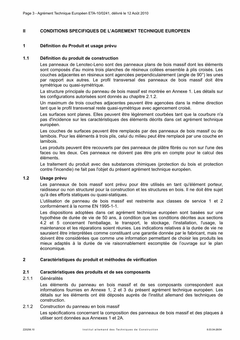
1.1 Définition du produit de construction
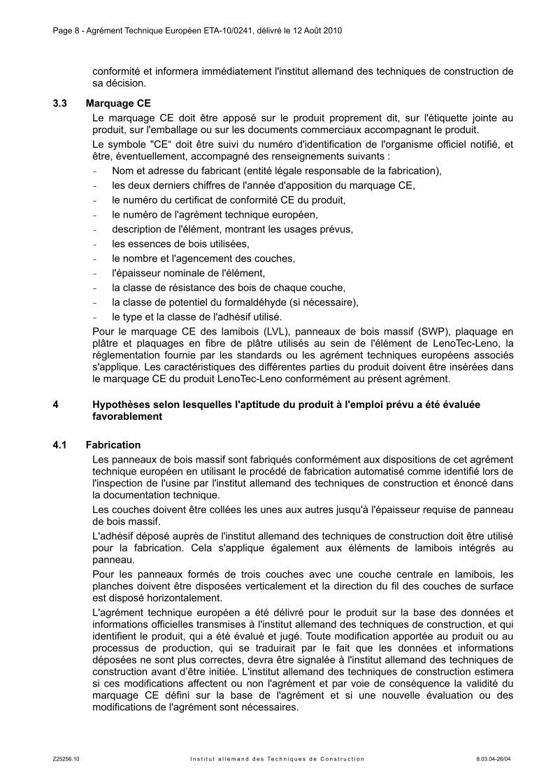
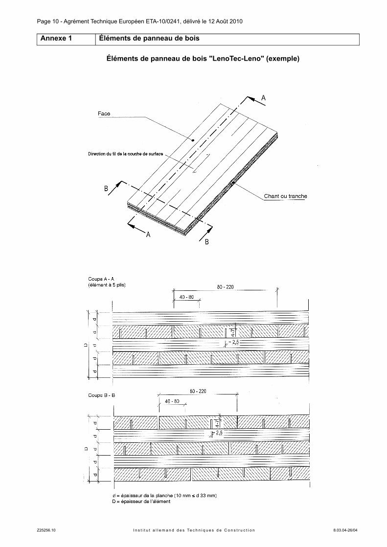
Les panneaux de Lenotec-Leno sont des panneaux plans de bois massif dont les éléments sont composés d'au moins trois planches de résineux collées ensemble à plis croisés. Les couches adjacentes en résineux sont agencées perpendiculairement (angle de 90°) les unes par rapport aux autres. Le profil transversal des panneaux de bois massif doit être symétrique ou quasi-symétrique.
La structure principale du panneau de bois massif est montrée en Annexe 1. Les détails sur les configurations autorisées sont donnés au chapitre 2.1.2.
Un maximum de trois couches adjacentes peuvent être agencées dans la même direction tant que le profil transversal reste quasi-symétrique avec agencement croisé.
Les surfaces sont planes. Elles peuvent être légèrement courbées tant que la courbure n'a pas d'incidence sur les caractéristiques des éléments décrits dans cet agrément technique européen.
Les couches de surfaces peuvent être remplacés par des panneaux de bois massif ou de lamibois. Pour les éléments à trois plis, celui du milieu peut être remplacé par une couche en lamibois.
Les produits peuvent être recouverts par des panneaux de plâtre fibrés ou non sur l'une des faces ou les deux. Ces panneaux ne doivent pas être pris en compte pour le calcul des éléments.
Le traitement du produit avec des substances chimiques (protection du bois et protection contre l'incendie) ne fait pas l'objet du présent agrément technique européen.
1.2 Usage prévu
Les panneaux de bois massif sont prévu pour être utilisés en tant qu'élément porteur, raidisseur ou non structurel pour la construction et les structures en bois. Il ne doit être sujet qu'à des efforts statiques ou quasi-statiques.
L'utilisation de panneau de bois massif est restreinte aux classes de service 1 et 2 conformément à la norme EN 1995-1-1.
Les dispositions adoptées dans cet agrément technique européen sont basées sur une hypothèse de durée de vie de 50 ans, à condition que les conditions décrites aux sections 4.2 et 5 concernant l'emballage, le transport, le stockage, l'installation, l'usage, la maintenance et les réparations soient réunies. Les indications relatives à la durée de vie ne sauraient être interprétées comme constituant une garantie donnée par le fabricant, mais ne doivent être considérées que comme une information permettant de choisir les produits les mieux adaptés à la durée de vie raisonnablement escomptée de l’ouvrage sur le plan économique.
2 Caractéristiques du produit et méthodes de vérification
2.1 Caractéristiques des produits et de ses composants
2.1.1 Généralités
Les éléments du panneau en bois massif et de ses composants correspondent aux informations fournies en Annexe 1, 2 et 3 du présent agrément technique européen. Les détails sur les éléments ont été déposés auprès de l'institut allemand des techniques de construction.
2.1.2 Construction du panneau en bois massif
Les spécifications concernant la composition des panneaux de bois massif et des plaques à utiliser sont données aux Annexes 1 et 2A.
Z25256.10 I n s t i t u t a l l e m a n d d e s Te c h n i q u e s d e C o n s t r u c t i o n 8.03.04-26/04
Page 4 - Agrément Technique Européen ETA-10/0241, délivré le 12 Août 2010
Les planches sont classées par résistance visuellement ou à la machine. Seul un bois techniquement séché doit être utilisé.
Seules des planches aplanies de chaque côté doivent utilisées. Les planches peuvent être assemblées dans le sens de la longueur par aboutages conformément à la norme EN 385. L’assemblage chant sur chant n’est pas autorisé.
Les éléments peuvent être connectés par aboutage à entures multiples conformément à la norme EN 3877.
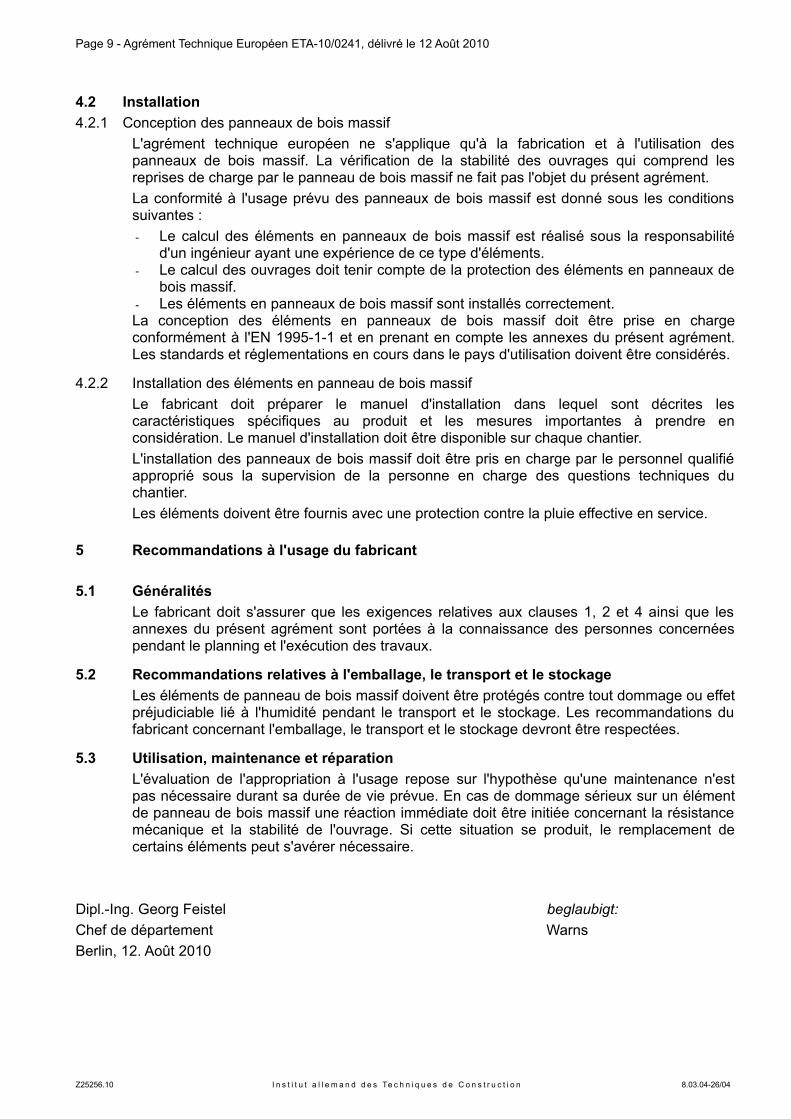
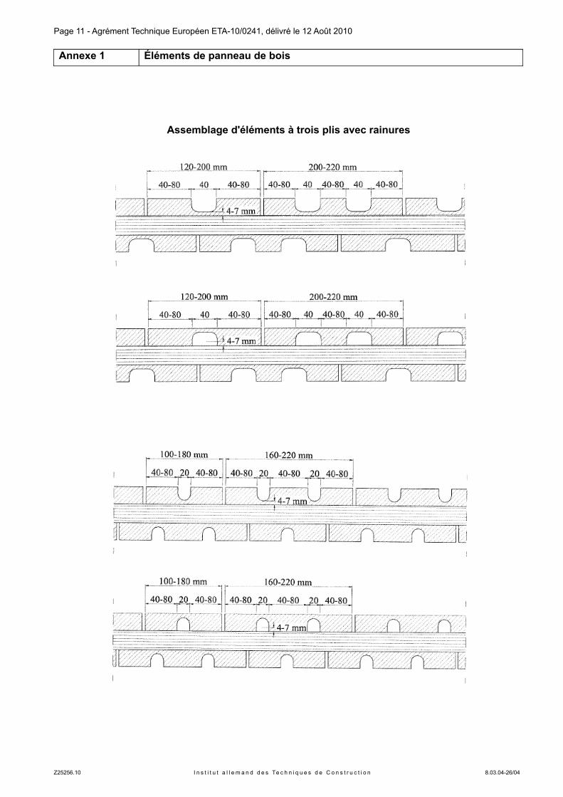
Les planches peuvent être percées par des entailles d'une largeur approximative de 2,5 mm à intervalle de 40 à 80mm. Pour les éléments à trois plaques, des entailles de largeur 20 mm ou 40 mm sont permises conformément à l'Annexe 2. La distance entre les entailles et entre l'entaille et le bord doit être entre 40 et 80 mm. L'épaisseur restante du panneau suivant la section des entailles doit être comprise entre 4 et 7 mm.
Les planches au sein de chacune des couches ne sont pas collées ensemble sur leur surface adjacente. La largeur acceptable des espacements est donnée en Annexe 2.
Si du lamibois de structure est utilisé comme couche de surface ou, pour les éléments à trois couches, comme couche centrale, il est nécessaire de remplir les conditions spécifiées par la norme EN 143748 et tel que déposé auprès de l'institut allemand des techniques de construction.
Si des panneaux de bois massif sont utilisés de même, il est nécessaire de remplir les conditions spécifiées par la norme EN 139869 ou dans un agrément technique européen.
Les lamibois de structure ou le panneau de bois massif doivent avoir une épaisseur maximale de 33 mm.
Si des couches additionnelles en panneau de plâtre ou fibre de plâtre, il est nécessaire de remplir les conditions spécifiées aux normes EN 52010 et EN 15283-211 ou dans un agrément technique européen. Les plaques de plâtre ou de fibre de plâtre ne doivent pas être pris en compte dans les calculs.
Les lamibois, les panneaux de bois massif, les plaques de plâtre ou de fibre de plâtre ne sont que des composants du produit « Lenotec-Leno ». Elles ne sont pas réglementées indépendamment dans cet agrément technique européen. Leur utilisation doit suivre les réglementations nationales peuvent.
La section transversale doit être symétrique. Dans le cas d'écarts à la symétrie, la distance entre la ligne d'effort neutre et le centre géométrique de la section transversale ne doit pas dépasser 1/10 de l'épaisseur de l'élément.
Les éléments peuvent être courbés en fonction de l'épaisseur des couches comme suit :
Épaisseur de la couche ≤ 12 mm rayon de courbure R ≥ 250·d,
Épaisseur de la couche > 12 et ≤ 17 mm rayon de courbure R ≥ 350·d,
Épaisseur de la couche > 17 et ≤ 22 mm rayon de courbure R ≥ 420·d,
Épaisseur de la couche > 22 et ≤ 27 mm rayon de courbure R ≥ 500·d,
avec
R = rayon de courbure d'une planche isolée
d = épaisseur d'une planche isolée au sein d'une couche
7EN 387:2001 Bois lamellé collé - Aboutages à entures multiples de grandes dimensions - Exigences de performance et exigences minimales de fabrication
8EN 14374:2004 Structures en bois - LVL (Lamibois) - Exigences9EN 13986:2004 Panneaux à base de bois destinés à la construction - Caractéristiques, évaluation de conformité
et marquage10EN 520:2004 Plaques de plâtre - Définitions, spécifications et méthodes d'essai11EN 15283-2:2009 Plaques de plâtre armées de fibres - Définitions, spécifications et méthodes d'essai -
Partie 2: Plaques de plâtre fibrées
Z25256.10 I n s t i t u t a l l e m a n d d e s Te c h n i q u e s d e C o n s t r u c t i o n 8.03.04-26/04
Page 5 - Agrément Technique Européen ETA-10/0241, délivré le 12 Août 2010
2.1.3 Adhésif
Dans le cas d'assemblage à entures multiples et de collage de planches séparées, il convient d'utiliser un adhésif de "Type I" correspondant à la norme EN 30112 ayant passé les tests conformément aux normes de EN 302-1 à EN 302-413. Un adhésif polyuréthanne satisfaisant aux exigences de la norme EN 1408014, Annexe C, peut être utilisé comme alternative. La norme EN 1542515 s'applique pour la classification.
Ces règles s'appliquent également pour les panneaux de bois massif et les lamibois intégrés au produit.
La colle utilisée doit être conforme aux informations déposées auprès de l'institut allemand des techniques de construction.
2.2 Résistance mécanique et stabilité
Les spécifications concernant la résistance mécanique et la stabilité sont données dans les Annexes 2 à 5. Le dimensionnement peut être réalisé conformément à la norme EN 1995-1-1.
2.3 Protection contre l'incendie
2.3.1 Comportement au feu
Selon la décision de la Commission 2003/43/EC, les éléments LenoTec-Leno couverts par le présent agrément technique européen et utilisés comme élément de mur, de toit, de plafond ou de construction spéciale se conforment à l'Euroclass D-s2,d0 en vertu de la norme EN 13501-116. Pour une utilisation en tant qu'élément de construction de plancher, ils se conforment à l'Euroclass DFL-s1. Les conditions aux limites énoncées dans la décision de la commission doivent suivre cette classification.
La décision de la Commission Européenne peut ne pas s'appliquer si l'élément comporte des couches supplémentaires, en fonction des couches utilisées et des conditions aux limites concernées.
Remarque : Un scenario d'incendie de référence en Europe pour les façades n'a pas été établi. Dans certains états membres, la classification des panneaux de bois massif conformément à la norme EN 13501-11 peut être insuffisante pour un usage en façade. Une évaluation supplémentaire des panneaux de bois massif conforme aux préconisations nationales (i.e. sur la base d'un test à grande échelle) peut être nécessaire pour se conformer aux législations de l'état membre, en attendant que le système de classification européen existant soit complété.
2.3.2 Résistance au feu
Les performances en terme de résistance au feu peuvent être calculées conformément à la norme EN 1995-1-2 en utilisant les vitesses de combustion données en Annexe 3. Les asymétries éventuelles doivent être prises en compte. La section restante ne doit pas être inférieure à 3mm.
12 EN 301:2006 Adhésifs de nature phénolique et aminoplaste, pour structures portantes en bois - Classification et exigences de performance
13 EN 302-1 to -4 Adhésifs pour structures portantes en bois - Méthodes d'essaiPartie 1: Détermination de la résistance du joint au cisaillement en traction longitudinale, 2004Partie 2: Détermination de la résistance au délaminage, 2004Partie 3: Détermination de l'influence de l'attaque d'acide des fibres de bois, résultant de traitements cycliques de température et d'humidité sur la résistance à la traction transversale, 2004 + A1:2005Partie 4: Détermination de l'influence du retrait du bois sur la résistance au cisaillement, 2004
14 EN 14080:2005 Structures en bois - Bois lamellé collé - Exigences15 EN 15425:2008 Adhésifs - Adhésifs polyuréthane monocomposants pour charpentes en bois portantes -
Classification et exigences relatives à la performance16 EN 13501-1:2007 Classement au feu des produits et éléments de construction
Partie 1: Classement à partir des données d’essais de réaction au feu
Z25256.10 I n s t i t u t a l l e m a n d d e s Te c h n i q u e s d e C o n s t r u c t i o n 8.03.04-26/04
Page 6 - Agrément Technique Européen ETA-10/0241, délivré le 12 Août 2010
2.4 Hygiène, santé et environnement
Sur la base des déclarations du fabricant, le produit soumis à l'agrément technique européen ne contient aucune substance nocive.
Les produits de protection du bois ou de protection incendie ne font pas partie du présent agrément technique européen.
Le potentiel en formaldéhyde est classé conformément à la norme EN 13986 se rapportant aux panneaux de bois massif.
Le produit Lenotec-Leno répond à la classification E1 pour les assemblages avec ou sans lamibois. Pour les assemblages avec des panneaux de bois massif la mention "aucune performance déterminée" s'applique.
Remarque : En plus des clauses spécifiques relatives aux substances dangereuses contenues dans le présent agrément technique européen, il peut y avoir d'autres conditions applicables au produit tombant dans leur champ d'application (par exemple la transposition de la législation européenne et des lois nationales, les règlements et les dispositions administratives). Pour respecter les dispositions de la directive sur les Produits de Construction, lesdites conditions doivent aussi s'y conformer, quand et lorsqu'elles s'appliquent.
2.5 Méthodes de vérification
L'aptitude des panneaux de bois massif à répondre à l'emploi prévu concernant les exigences de résistance mécanique et de stabilité, la sécurité incendie, l'hygiène, la santé et l'environnement, la protection contre le bruit, l'économie d'énergie et la rétention de chaleur ainsi que la durabilité au sens de ces Essentiels est évaluée conformément aux règles d'évaluation des panneaux de bois massif certifiées par EOTA.
3 Évaluation et attestation de conformité et marquage CE
3.1 Système d'attestation de conformité
Conformément à la Décision 97/176/EC17 de la Commission Européenne pour la famille de produit 2/3, le Système 1 d'attestation de conformité sera appliqué.
Ce système d'attestation de conformité est décrit ci-après :
Système 1 : Certification de conformité du produit par un organisme de certification habilité sur la base des dispositions suivantes : (a) Obligations du fabricant :
(1) Contrôle de production en usine ; (2) Essais sur des échantillons prélevés en usine par le fabricant conformément au plan de contrôle défini ;
(b) Obligations de l’organisme officiel : (3) Essais de types initiaux du produit ; (4) Inspection initiale de l'usine et du contrôle de production en usine ; (5) Surveillance continue, évaluation et approbation du contrôle de production en usine.
Remarque : les organismes officiels habilités sont également désignés sous le terme « organismes notifiés ».
17 Journal officiel des communautés européennes L 73/19 de 03/1997
Z25256.10 I n s t i t u t a l l e m a n d d e s Te c h n i q u e s d e C o n s t r u c t i o n 8.03.04-26/04
Page 7 - Agrément Technique Européen ETA-10/0241, délivré le 12 Août 2010
3.2 Responsabilités
3.2.1 Obligations du fabricant
3.2.1.1 Contrôle de la production en usine
Le fabricant procédera à un contrôle interne permanent de la production. Toutes les informations, exigences et réglementations adoptées par le fabricant seront systématiquement reprises dans des documents, sous forme de procédures et modes opératoires écrits. Le contrôle de production en usine permettra de garantir que le produit est conforme aux dispositions de l'agrément technique européen.
Le fabricant n'utilisera que les matières premières spécifiées dans les documents techniques du présent agrément technique européen.
Le contrôle de production en usine sera effectué conformément au « Plan de contrôle du 12 Août 2010 relatif à l'agrément technique européen ETA-10/0241" délivré le 12 Août 2010 qui fait partie intégrante de la documentation technique du présent agrément technique européen. Le « Plan de Contrôle » est rédigé dans le cadre du système de contrôle de production en usine géré par le fabricant et déposé auprès de l'institut allemand des techniques de construction.18
Les résultats du contrôle de production en usine seront enregistrés et évalués conformément aux dispositions du « Plan de Contrôle ». Ces enregistrements contiennent au moins :
− Dénomination du produit, matériaux de base et composants ;
− Type contrôle ou d'essai ;
− Date de fabrication du produit et date d'essais sur le produit, les matériaux de base ou les composants ;
− Résultats des contrôles et essais et comparaison avec les exigences si c'est approprié ;
− Nom et signature du responsable du contrôle de production de l'usine.
3.2.1.2 Autres obligations du fabricant
Le fabricant fera appel, dans le cadre d'un contrat, à un organisme habilité pour l'ensemble des missions définies au paragraphe 3.1 pour exécuter les opérations définies au paragraphe 3.2.2. A cet effet, le « plan de contrôle » mentionné aux paragraphes 3.2.1.1 et 3.2.2 sera transmis par le fabricant à l'organisme habilité compétent.
Le fabricant rédigera une déclaration de conformité, mentionnant que les produits de construction sont en conformité avec les dispositions de l'agrément technique européen ETA-10/0241 délivré le 12 Août 2010. La déclaration de conformité ne peut être donnée que si les dispositions du présent agrément sont réunies et si le plan de contrôle a été suivi.
3.2.2 Obligations de l'organisme officiel
L'organisme officiel sera responsable des tâches suivantes :
- Essais de type initiaux du produit,
- Inspection initiale de l'usine et contrôle de production en usine,
- Surveillance continue, évaluation et approbation du contrôle continu en usine,
conformément aux dispositions énoncées dans le plan de contrôle.
L'inspection initiale de l'usine comprendra l'inspection des locaux, des équipements techniques de l'usine et la qualification du personnel.
L’organisme officiel notera tous les points essentiels de son intervention tels que définis ci-dessus et notera les résultats obtenus ainsi que ses conclusions dans un rapport écrit.
L'organisme de certification officiel désigné par le fabricant délivrera un certificat de conformité CE pour le produit établissant le respect des dispositions du présent agrément technique européen. Le certificat de conformité ne peut être délivré que si les dispositions du présent agrément sont réunies et le plan de contrôle suivi.
Au cas ou les dispositions de l'agrément technique européen et du plan de contrôle applicable ne seraient plus respectées, l'organisme de certification retirera le certificat de
18 Le “plan de contrôle“ est confidentiel dans cet agrément technique européen et n'est remis à l'organisme agréé concerné que dans le cadre de la procédure d'attestation de conformité. Voir section 3.2.2.
Z25256.10 I n s t i t u t a l l e m a n d d e s Te c h n i q u e s d e C o n s t r u c t i o n 8.03.04-26/04
Page 8 - Agrément Technique Européen ETA-10/0241, délivré le 12 Août 2010
conformité et informera immédiatement l'institut allemand des techniques de construction de sa décision.
3.3 Marquage CE
Le marquage CE doit être apposé sur le produit proprement dit, sur l'étiquette jointe au produit, sur l'emballage ou sur les documents commerciaux accompagnant le produit.
Le symbole "CE“ doit être suivi du numéro d'identification de l'organisme officiel notifié, et être, éventuellement, accompagné des renseignements suivants :
- Nom et adresse du fabricant (entité légale responsable de la fabrication),
- les deux derniers chiffres de l'année d'apposition du marquage CE,
- le numéro du certificat de conformité CE du produit,
- le numéro de l'agrément technique européen,
- description de l'élément, montrant les usages prévus,
- les essences de bois utilisées,
- le nombre et l'agencement des couches,
- l'épaisseur nominale de l'élément,
- la classe de résistance des bois de chaque couche,
- la classe de potentiel du formaldéhyde (si nécessaire),
- le type et la classe de l'adhésif utilisé.
Pour le marquage CE des lamibois (LVL), panneaux de bois massif (SWP), plaquage en plâtre et plaquages en fibre de plâtre utilisés au sein de l'élément de LenoTec-Leno, la réglementation fournie par les standards ou les agrément techniques européens associés s'applique. Les caractéristiques des différentes parties du produit doivent être insérées dans le marquage CE du produit LenoTec-Leno conformément au présent agrément.
4 Hypothèses selon lesquelles l'aptitude du produit a l'emploi prévu a été évaluée favorablement
4.1 Fabrication
Les panneaux de bois massif sont fabriqués conformément aux dispositions de cet agrément technique européen en utilisant le procédé de fabrication automatisé comme identifié lors de l'inspection de l'usine par l'institut allemand des techniques de construction et énoncé dans la documentation technique.
Les couches doivent être collées les unes aux autres jusqu'à l'épaisseur requise de panneau de bois massif.
L'adhésif déposé auprès de l'institut allemand des techniques de construction doit être utilisé pour la fabrication. Cela s'applique également aux éléments de lamibois intégrés au panneau.
Pour les panneaux formés de trois couches avec une couche centrale en lamibois, les planches doivent être disposées verticalement et la direction du fil des couches de surface est disposé horizontalement.
L'agrément technique européen a été délivré pour le produit sur la base des données et informations officielles transmises à l'institut allemand des techniques de construction, et qui identifient le produit, qui a été évalué et jugé. Toute modification apportée au produit ou au processus de production, qui se traduirait par le fait que les données et informations déposées ne sont plus correctes, devra être signalée à l'institut allemand des techniques de construction avant d’être initiée. L'institut allemand des techniques de construction estimera si ces modifications affectent ou non l'agrément et par voie de conséquence la validité du marquage CE défini sur la base de l'agrément et si une nouvelle évaluation ou des modifications de l'agrément sont nécessaires.
Z25256.10 I n s t i t u t a l l e m a n d d e s Te c h n i q u e s d e C o n s t r u c t i o n 8.03.04-26/04
Page 9 - Agrément Technique Européen ETA-10/0241, délivré le 12 Août 2010
4.2 Installation
4.2.1 Conception des panneaux de bois massif
L'agrément technique européen ne s'applique qu'à la fabrication et à l'utilisation des panneaux de bois massif. La vérification de la stabilité des ouvrages qui comprend les reprises de charge par le panneau de bois massif ne fait pas l'objet du présent agrément.
La conformité à l'usage prévu des panneaux de bois massif est donné sous les conditions suivantes :
- Le calcul des éléments en panneaux de bois massif est réalisé sous la responsabilité d'un ingénieur ayant une expérience de ce type d'éléments.
- Le calcul des ouvrages doit tenir compte de la protection des éléments en panneaux de bois massif.
- Les éléments en panneaux de bois massif sont installés correctement.La conception des éléments en panneaux de bois massif doit être prise en charge conformément à l'EN 1995-1-1 et en prenant en compte les annexes du présent agrément. Les standards et réglementations en cours dans le pays d'utilisation doivent être considérés.
4.2.2 Installation des éléments en panneau de bois massif
Le fabricant doit préparer le manuel d'installation dans lequel sont décrites les caractéristiques spécifiques au produit et les mesures importantes à prendre en considération. Le manuel d'installation doit être disponible sur chaque chantier.
L'installation des panneaux de bois massif doit être pris en charge par le personnel qualifié approprié sous la supervision de la personne en charge des questions techniques du chantier.
Les éléments doivent être fournis avec une protection contre la pluie effective en service.
5 Recommandations a l'usage du fabricant
5.1 Généralités
Le fabricant doit s'assurer que les exigences relatives aux clauses 1, 2 et 4 ainsi que les annexes du présent agrément sont portées à la connaissance des personnes concernées pendant le planning et l'exécution des travaux.
5.2 Recommandations relatives a l'emballage, le transport et le stockage
Les éléments de panneau de bois massif doivent être protégés contre tout dommage ou effet préjudiciable lié à l'humidité pendant le transport et le stockage. Les recommandations du fabricant concernant l'emballage, le transport et le stockage devront être respectées.
5.3 Utilisation, maintenance et réparation
L'évaluation de l'appropriation à l'usage repose sur l'hypothèse qu'une maintenance n'est pas nécessaire durant sa durée de vie prévue. En cas de dommage sérieux sur un élément de panneau de bois massif une réaction immédiate doit être initiée concernant la résistance mécanique et la stabilité de l'ouvrage. Si cette situation se produit, le remplacement de certains éléments peut s'avérer nécessaire.
Dipl.-Ing. Georg Feistel beglaubigt:
Chef de département Warns
Berlin, 12. Août 2010
Z25256.10 I n s t i t u t a l l e m a n d d e s Te c h n i q u e s d e C o n s t r u c t i o n 8.03.04-26/04
Page 10 - Agrément Technique Européen ETA-10/0241, délivré le 12 Août 2010
Annexe 1 Éléments de panneau de bois
Éléments de panneau de bois "LenoTec-Leno" (exemple)
Z25256.10 I n s t i t u t a l l e m a n d d e s Te c h n i q u e s d e C o n s t r u c t i o n 8.03.04-26/04
Page 11 - Agrément Technique Européen ETA-10/0241, délivré le 12 Août 2010
Annexe 1 Éléments de panneau de bois
Assemblage d'éléments a trois plis avec rainures
Z25256.10 I n s t i t u t a l l e m a n d d e s Te c h n i q u e s d e C o n s t r u c t i o n 8.03.04-26/04
Page 12 - Agrément Technique Européen ETA-10/0241, délivré le 12 Août 2010
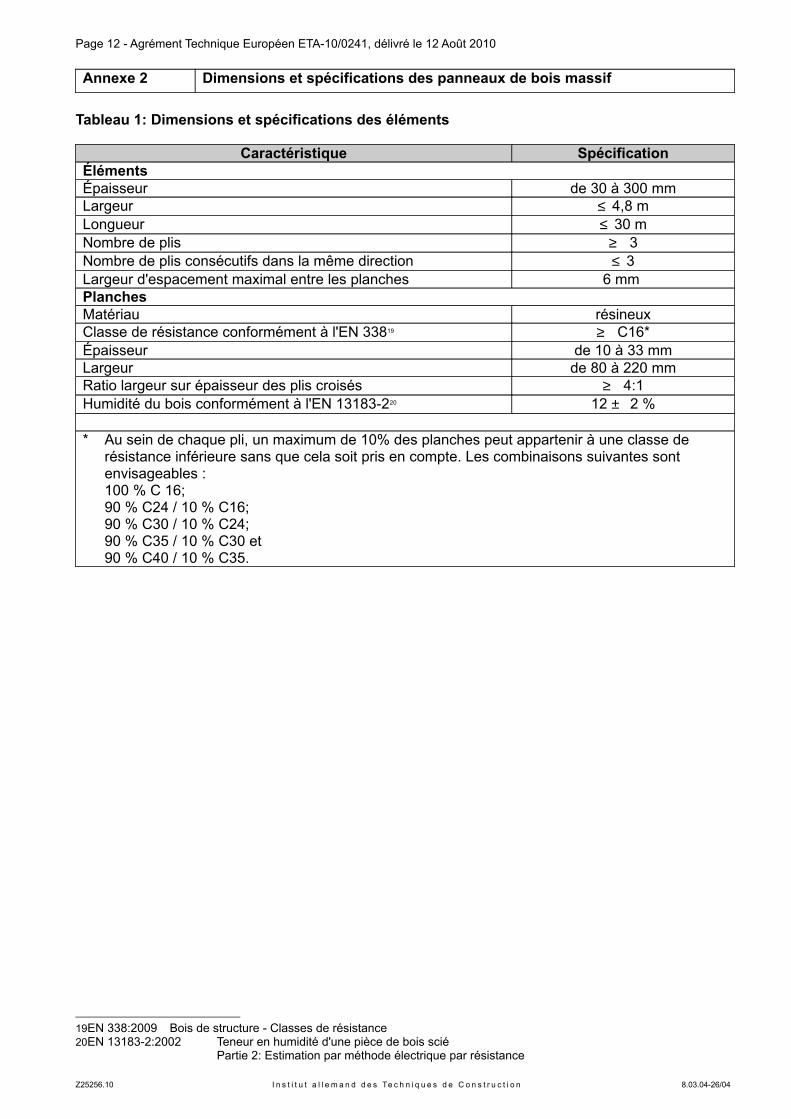
Annexe 2 Dimensions et spécifications des panneaux de bois massif
Tableau 1: Dimensions et spécifications des éléments
Caractéristique SpécificationÉlémentsÉpaisseur de 30 à 300 mmLargeur ≤ 4,8 mLongueur ≤ 30 mNombre de plis ≥ 3Nombre de plis consécutifs dans la même direction ≤ 3Largeur d'espacement maximal entre les planches 6 mm PlanchesMatériau résineuxClasse de résistance conformément à l'EN 33819 ≥ C16*Épaisseur de 10 à 33 mmLargeur de 80 à 220 mmRatio largeur sur épaisseur des plis croisés ≥ 4:1Humidité du bois conformément à l'EN 13183-220 12 ± 2 %
* Au sein de chaque pli, un maximum de 10% des planches peut appartenir à une classe de résistance inférieure sans que cela soit pris en compte. Les combinaisons suivantes sont envisageables : 100 % C 16;90 % C24 / 10 % C16; 90 % C30 / 10 % C24; 90 % C35 / 10 % C30 et90 % C40 / 10 % C35.
19EN 338:2009 Bois de structure - Classes de résistance20EN 13183-2:2002 Teneur en humidité d'une pièce de bois scié
Partie 2: Estimation par méthode électrique par résistance
Z25256.10 I n s t i t u t a l l e m a n d d e s Te c h n i q u e s d e C o n s t r u c t i o n 8.03.04-26/04
Page 13 - Agrément Technique Européen ETA-10/0241, délivré le 12 Août 2010
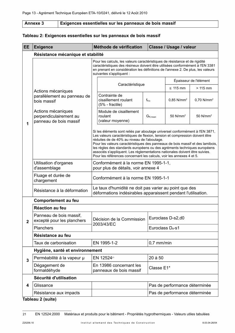
Annexe 3 Exigences essentielles sur les panneaux de bois massif
Tableau 2: Exigences essentielles sur les panneaux de bois massif
EE Exigence Méthode de vérification Classe / Usage / valeur
1
Résistance mécanique et stabilité
Actions mécaniques parallèlement au panneau de bois massif
Actions mécaniques perpendiculairement au panneau de bois massif
Pour les calculs, les valeurs caractéristiques de résistance et de rigidité caractéristiques des résineux doivent être utilisées conformément à l'EN 3381 en prenant en considération les définitions de l'annexe 2. De plus, les valeurs suivantes s'appliquent :
CaractéristiqueÉpaisseur de l'élément
≤ 115 mm > 115 mm
Contrainte de cisaillement roulant (5% - fractile)
fR,k 0,85 N/mm2 0,70 N/mm2
Module de cisaillement roulant(valeur moyenne)
GR,mean 50 N/mm2 50 N/mm2
Si les éléments sont reliés par aboutage universel conformément à l'EN 3871, Les valeurs caractéristiques de flexion, tension et compression doivent être réduites de de 40% au niveau de l'aboutage.Pour les valeurs caractéristiques des panneaux de bois massif et des lamibois, les règles des standards européens ou des agréments techniques européens associés s'appliquent. Les réglementations nationales doivent être suivies.Pour les références concernant les calculs, voir les annexes 4 et 5.
Utilisation d'organes d'assemblage
Conformément à la norme EN 1995-1-1,pour plus de détails, voir annexe 4
Fluage et durée de chargement
Conformément à la norme EN 1995-1-1
Résistance à la déformationLe taux d'humidité ne doit pas varier au point que des déformations indésirables apparaissent pendant l'utilisation.
2
Comportement au feu
Réaction au feu
Panneau de bois massif, excepté pour les planchers Décision de la Commission
2003/43/EC
Euroclass D-s2,d0
Planchers Euroclass Dfl-s1
Résistance au feu
Taux de carbonisation EN 1995-1-2 0,7 mm/min
3
Hygiène, santé et environnement
Perméabilité à la vapeur µ EN 1252421 20 à 50
Dégagement de formaldéhyde
En 13986 concernant les panneaux de bois massif
Classe E1*
4
Sécurité d'utilisation
Glissance Pas de performance déterminée
Résistance aux impacts Pas de performance déterminée
Tableau 2 (suite)
21 EN 12524:2000 Matériaux et produits pour le bâtiment - Propriétés hygrothermiques - Valeurs utiles tabulées
Z25256.10 I n s t i t u t a l l e m a n d d e s Te c h n i q u e s d e C o n s t r u c t i o n 8.03.04-26/04
Page 14 - Agrément Technique Européen ETA-10/0241, délivré le 12 Août 2010
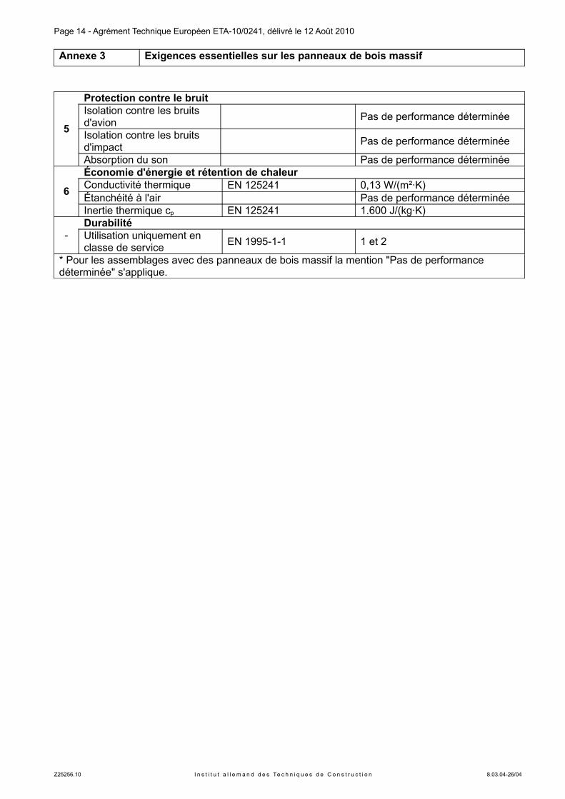
Annexe 3 Exigences essentielles sur les panneaux de bois massif
5
Protection contre le bruitIsolation contre les bruits d'avion
Pas de performance déterminée
Isolation contre les bruits d'impact
Pas de performance déterminée
Absorption du son Pas de performance déterminée
6
Économie d'énergie et rétention de chaleurConductivité thermique � EN 125241 0,13 W/(m²·K)Étanchéité à l'air Pas de performance déterminéeInertie thermique cp EN 125241 1.600 J/(kg·K)
-DurabilitéUtilisation uniquement en classe de service
EN 1995-1-1 1 et 2
* Pour les assemblages avec des panneaux de bois massif la mention "Pas de performance déterminée" s'applique.
Z25256.10 I n s t i t u t a l l e m a n d d e s Te c h n i q u e s d e C o n s t r u c t i o n 8.03.04-26/04
Page 15 - Agrément Technique Européen ETA-10/0241, délivré le 12 Août 2010
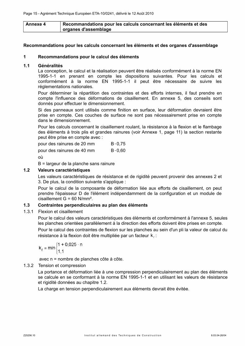
Annexe 4 Recommandations pour les calculs concernant les éléments et des organes d'assemblage
Recommandations pour les calculs concernant les éléments et des organes d'assemblage
1 Recommandations pour le calcul des éléments
1.1 GénéralitésLa conception, le calcul et la réalisation peuvent être réalisés conformément à la norme EN 1995-1-1 en prenant en compte les dispositions suivantes. Pour les calculs et conformément à la norme EN 1995-1-1 il peut être nécessaire de suivre les réglementations nationales.
Pour déterminer la répartition des contraintes et des efforts internes, il faut prendre en compte l'influence des déformations de cisaillement. En annexe 5, des conseils sont donnés pour effectuer le dimensionnement.
Si des panneaux sont utilisés comme finition en surface, leur déformation devraient être prise en compte. Ces couches de surface ne sont pas nécessairement prise en compte dans le dimensionnement.
Pour les calculs concernant le cisaillement roulant, la résistance à la flexion et le flambage des éléments à trois plis et grandes rainures (voir Annexe 1, page 11) la section restante peut être prise en compte avec :
pour des rainures de 20 mm B·0,75
pour des rainures de 40 mm B·0,60
ou
B = largeur de la planche sans rainure
1.2 Valeurs caractéristiques
Les valeurs caractéristiques de résistance et de rigidité peuvent provenir des annexes 2 et 3. De plus, la condition suivante s'applique :
Pour le calcul de la composante de déformation liée aux efforts de cisaillement, on peut prendre l'épaisseur D de l'élément indépendamment de la configuration et un module de cisaillement G = 60 N/mm².
1.3 Contraintes perpendiculaires au plan des éléments
1.3.1 Flexion et cisaillement
Pour le calcul des valeurs caractéristiques des éléments et conformément à l'annexe 5, seules les planches orientées parallèlement à la direction des efforts doivent être prises en compte.
Pour le calcul des contraintes de flexion sur les planches au sein d'un pli la valeur de calcul du résistance à la flexion doit être multipliée par un facteur lk :
avec n = nombre de planches côte à côte.
1.3.2 Tension et compression
La portance et déformation liée à une compression perpendiculairement au plan des éléments se calcule en se conformant à la norme EN 1995-1-1 et en utilisant les valeurs de résistance et rigidité données au chapitre 1.2.
La charge en tension perpendiculairement aux éléments devrait être évitée.
Z25256.10 I n s t i t u t a l l e m a n d d e s Te c h n i q u e s d e C o n s t r u c t i o n 8.03.04-26/04
Page 16 - Agrément Technique Européen ETA-10/0241, délivré le 12 Août 2010
Annexe 4 Recommandations pour les calculs concernant les éléments et des organes d'assemblage
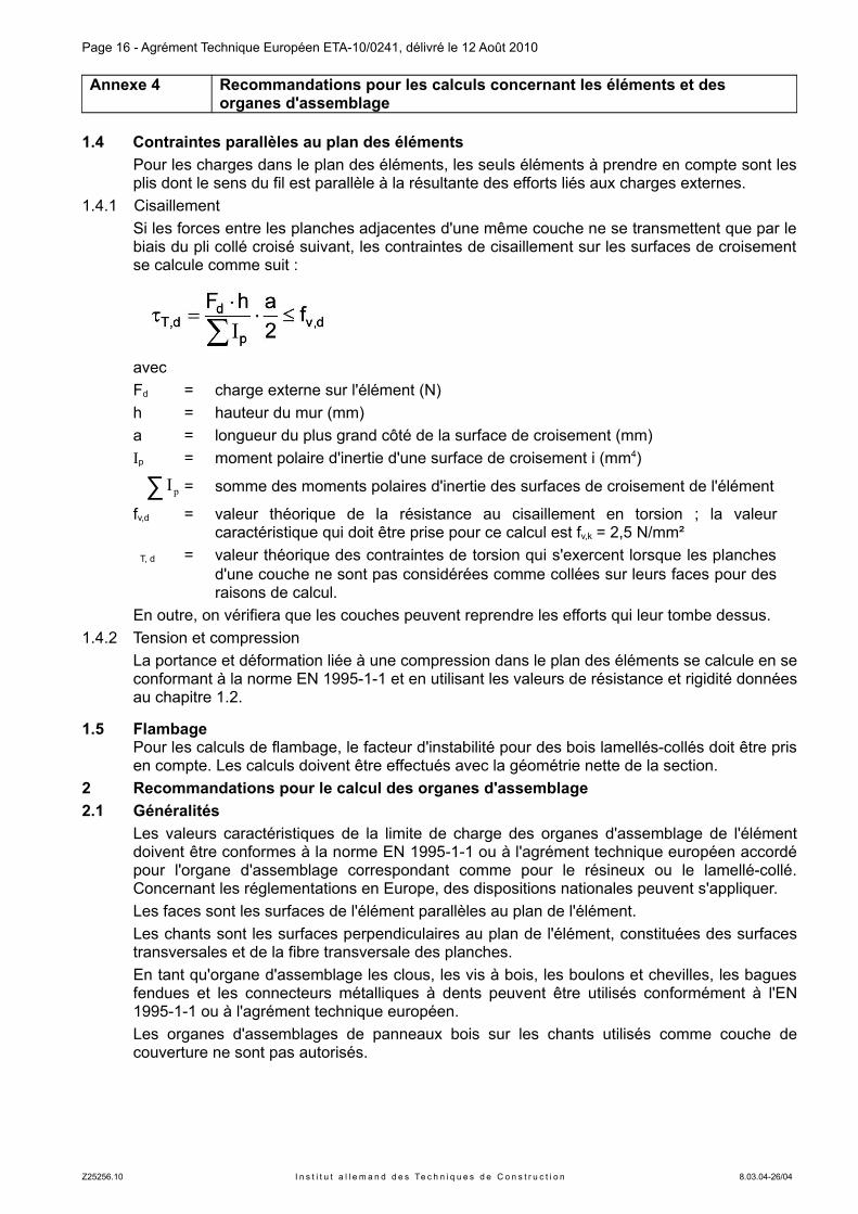
1.4 Contraintes parallèles au plan des éléments
Pour les charges dans le plan des éléments, les seuls éléments à prendre en compte sont les plis dont le sens du fil est parallèle à la résultante des efforts liés aux charges externes.
1.4.1 Cisaillement
Si les forces entre les planches adjacentes d'une même couche ne se transmettent que par le biais du pli collé croisé suivant, les contraintes de cisaillement sur les surfaces de croisement se calcule comme suit :
avec
Fd = charge externe sur l'élément (N)
h = hauteur du mur (mm)
a = longueur du plus grand côté de la surface de croisement (mm)
Ip = moment polaire d'inertie d'une surface de croisement i (mm4)
∑ pI = somme des moments polaires d'inertie des surfaces de croisement de l'élément
fv,d = valeur théorique de la résistance au cisaillement en torsion ; la valeur caractéristique qui doit être prise pour ce calcul est fv,k = 2,5 N/mm²
� T, d = valeur théorique des contraintes de torsion qui s'exercent lorsque les planches d'une couche ne sont pas considérées comme collées sur leurs faces pour des raisons de calcul.
En outre, on vérifiera que les couches peuvent reprendre les efforts qui leur tombe dessus.
1.4.2 Tension et compression
La portance et déformation liée à une compression dans le plan des éléments se calcule en se conformant à la norme EN 1995-1-1 et en utilisant les valeurs de résistance et rigidité données au chapitre 1.2.
1.5 FlambagePour les calculs de flambage, le facteur d'instabilité pour des bois lamellés-collés doit être pris en compte. Les calculs doivent être effectués avec la géométrie nette de la section.
2 Recommandations pour le calcul des organes d'assemblage
2.1 Généralités
Les valeurs caractéristiques de la limite de charge des organes d'assemblage de l'élément doivent être conformes à la norme EN 1995-1-1 ou à l'agrément technique européen accordé pour l'organe d'assemblage correspondant comme pour le résineux ou le lamellé-collé. Concernant les réglementations en Europe, des dispositions nationales peuvent s'appliquer.
Les faces sont les surfaces de l'élément parallèles au plan de l'élément.
Les chants sont les surfaces perpendiculaires au plan de l'élément, constituées des surfaces transversales et de la fibre transversale des planches.
En tant qu'organe d'assemblage les clous, les vis à bois, les boulons et chevilles, les bagues fendues et les connecteurs métalliques à dents peuvent être utilisés conformément à l'EN 1995-1-1 ou à l'agrément technique européen.
Les organes d'assemblages de panneaux bois sur les chants utilisés comme couche de couverture ne sont pas autorisés.
Z25256.10 I n s t i t u t a l l e m a n d d e s Te c h n i q u e s d e C o n s t r u c t i o n 8.03.04-26/04
Page 17 - Agrément Technique Européen ETA-10/0241, délivré le 12 Août 2010
Annexe 4 Recommandations pour les calculs concernant les éléments et des organes d'assemblage
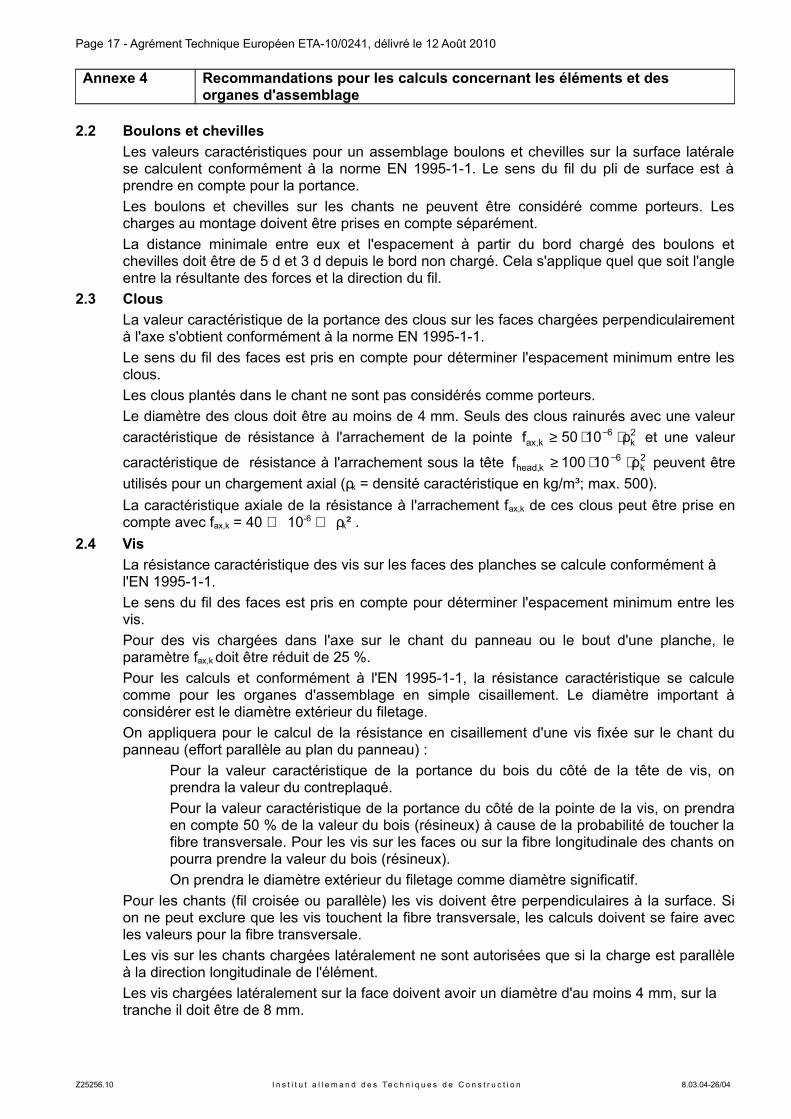
2.2 Boulons et chevilles
Les valeurs caractéristiques pour un assemblage boulons et chevilles sur la surface latérale se calculent conformément à la norme EN 1995-1-1. Le sens du fil du pli de surface est à prendre en compte pour la portance.
Les boulons et chevilles sur les chants ne peuvent être considéré comme porteurs. Les charges au montage doivent être prises en compte séparément.
La distance minimale entre eux et l'espacement à partir du bord chargé des boulons et chevilles doit être de 5 d et 3 d depuis le bord non chargé. Cela s'applique quel que soit l'angle entre la résultante des forces et la direction du fil.
2.3 Clous
La valeur caractéristique de la portance des clous sur les faces chargées perpendiculairement à l'axe s'obtient conformément à la norme EN 1995-1-1.
Le sens du fil des faces est pris en compte pour déterminer l'espacement minimum entre les clous.
Les clous plantés dans le chant ne sont pas considérés comme porteurs.
Le diamètre des clous doit être au moins de 4 mm. Seuls des clous rainurés avec une valeur
caractéristique de résistance à l'arrachement de la pointe 2k
6k,ax 1050f ρ⋅⋅≥ − et une valeur
caractéristique de résistance à l'arrachement sous la tête 2k
6k,head 10100f ρ⋅⋅≥ − peuvent être
utilisés pour un chargement axial (ρk = densité caractéristique en kg/m³; max. 500).
La caractéristique axiale de la résistance à l'arrachement fax,k de ces clous peut être prise en compte avec fax,k = 40 ⋅ 10-6 ⋅ ρk² .
2.4 Vis
La résistance caractéristique des vis sur les faces des planches se calcule conformément à l'EN 1995-1-1.
Le sens du fil des faces est pris en compte pour déterminer l'espacement minimum entre les vis.
Pour des vis chargées dans l'axe sur le chant du panneau ou le bout d'une planche, le paramètre fax,k doit être réduit de 25 %.
Pour les calculs et conformément à l'EN 1995-1-1, la résistance caractéristique se calcule comme pour les organes d'assemblage en simple cisaillement. Le diamètre important à considérer est le diamètre extérieur du filetage.
On appliquera pour le calcul de la résistance en cisaillement d'une vis fixée sur le chant du panneau (effort parallèle au plan du panneau) :
Pour la valeur caractéristique de la portance du bois du côté de la tête de vis, on prendra la valeur du contreplaqué.
Pour la valeur caractéristique de la portance du côté de la pointe de la vis, on prendra en compte 50 % de la valeur du bois (résineux) à cause de la probabilité de toucher la fibre transversale. Pour les vis sur les faces ou sur la fibre longitudinale des chants on pourra prendre la valeur du bois (résineux).
On prendra le diamètre extérieur du filetage comme diamètre significatif.
Pour les chants (fil croisée ou parallèle) les vis doivent être perpendiculaires à la surface. Si on ne peut exclure que les vis touchent la fibre transversale, les calculs doivent se faire avec les valeurs pour la fibre transversale.
Les vis sur les chants chargées latéralement ne sont autorisées que si la charge est parallèle à la direction longitudinale de l'élément.
Les vis chargées latéralement sur la face doivent avoir un diamètre d'au moins 4 mm, sur la tranche il doit être de 8 mm.
Z25256.10 I n s t i t u t a l l e m a n d d e s Te c h n i q u e s d e C o n s t r u c t i o n 8.03.04-26/04
Page 18 - Agrément Technique Européen ETA-10/0241, délivré le 12 Août 2010
Annexe 4 Recommandations pour les calculs concernant les éléments et des organes d'assemblage
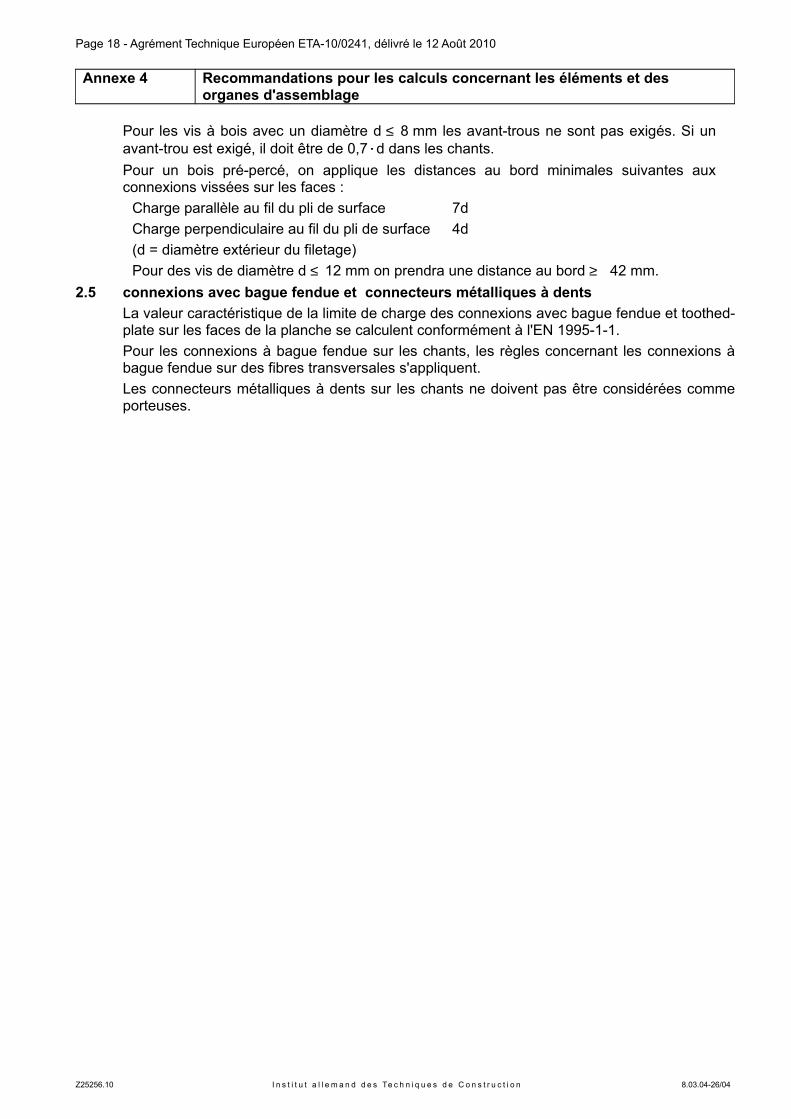
Pour les vis à bois avec un diamètre d ≤ 8 mm les avant-trous ne sont pas exigés. Si un avant-trou est exigé, il doit être de 0,7·d dans les chants.
Pour un bois pré-percé, on applique les distances au bord minimales suivantes aux connexions vissées sur les faces :
Charge parallèle au fil du pli de surface 7d
Charge perpendiculaire au fil du pli de surface 4d
(d = diamètre extérieur du filetage)
Pour des vis de diamètre d ≤ 12 mm on prendra une distance au bord ≥ 42 mm.
2.5 connexions avec bague fendue et connecteurs métalliques a dents
La valeur caractéristique de la limite de charge des connexions avec bague fendue et toothed-plate sur les faces de la planche se calculent conformément à l'EN 1995-1-1.
Pour les connexions à bague fendue sur les chants, les règles concernant les connexions à bague fendue sur des fibres transversales s'appliquent.
Les connecteurs métalliques à dents sur les chants ne doivent pas être considérées comme porteuses.
Z25256.10 I n s t i t u t a l l e m a n d d e s Te c h n i q u e s d e C o n s t r u c t i o n 8.03.04-26/04
Page 19 - Agrément Technique Européen ETA-10/0241, délivré le 12 Août 2010
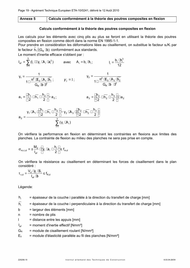
Annexe 5 Calculs conformément a la théorie des poutres composites en flexion
Calculs conformément a la théorie des poutres composites en flexion
Les calculs pour les éléments avec cinq plis au plus se feront en utilisant la théorie des poutres composites en flexion comme décrit dans la norme EN 1995-1-1.Pour prendre en considération les déformations liées au cisaillement, on substitue le facteur si/Ki par le facteur )bG(h Ri ⋅ conformément aux standards.
Le moment d'inertie efficace s'obtient par :
∑=
⋅⋅γ+⋅=3
1i
2iiiief )aAI(I avec iii hbA ⋅= ;
12
hbI
3ii
i
⋅=
2R
11021
lbG
hAE1
1
⋅⋅⋅⋅⋅π+
=γ; 12 =γ ;
2R
23023
lbG
hAE1
1
⋅⋅⋅⋅⋅π+
=γ
22
11
1 a2
hh
2
ha −
++= ; 2
32
23 a
2
hh
2
ha +
++=
∑=
⋅γ
++⋅⋅γ−
++⋅⋅γ
=3
1iii
32
233
21
111
2
)A(
2
hh
2
hA
2
hh
2
hA
a
On vérifiera la performance en flexion en déterminant les contraintes en flexions aux limites des planches. La contrainte de flexion au milieu des planches ne sera pas prise en compte.
d,mi
iief
dd,i,r,m f
2
ha
I
M≤
+⋅γ⋅±=σ
On vérifiera la résistance au cisaillement en déterminant les forces de cisaillement dans le plan considéré :
d,Ref
iidd,v f
bI
SV≤
⋅⋅γ⋅
=τ
Légende:
ih = épaisseur de la couche i parallèle à la direction du transfert de charge [mm]
ih = épaisseur de la couche i perpendiculaire à la direction du transfert de charge [mm]
b = largeur des éléments [mm]
n = nombre de plis
l = distance entre les appuis [mm]
efI = moment d'inertie effectif [Nmm²]
GR = module de cisaillement roulant [N/mm²]
E0 = module d'élasticité parallèle au fil des planches [N/mm²]
Z25256.10 I n s t i t u t a l l e m a n d d e s Te c h n i q u e s d e C o n s t r u c t i o n 8.03.04-26/04
Diese Zulassung umfasst
This Approval contains
19 Seiten einschließlich 5 Anhänge 19 pages including 5 annexes
E u r o p ä i s c h e O r g a n i s a t i o n f ü r T e c h n i s c h e Z u l a s s u n g e n
E u r o p e a n O r g a n i s a t i o n f o r T e c h n i c a l A p p r o v a l s
Deutsches Institut für Bautechnik Anstalt des öffentlichen Rechts
Kolonnenstr. 30 L 10829 Berlin Deutschland
Tel.: +49(0)30 787 30 0 Fax: +49(0)30 787 30 320 E-mail: [email protected] Internet: www.dibt.de
Ermächtigtu n d n o t i f i z i e r t
gemäß Artikel 10 derRichtlinie des Rates vom
21. Dezember 1988 zur An-gleichung der Rechts- undVerwaltungsvorschriften
der Mi tg l ie ds taa tenüber Bauprodukte
(89/106/EWG)
Mitglied der EOTA Member of EOTA
Europäische Technische Zulassung ETA-10/0241
Handelsbezeichnung Trade name
LenoTec LenoTec
Zulassungsinhaber
Holder of approval Finnforest Merk GmbH Industriestraße 2 86551 Aichach
Zulassungsgegenstand und Verwendungszweck
Massive plattenförmige Holzbauelemente zur Verwendung als tragende Teile in Bauwerken
Generic type and use of construction product
Solid wood slab elements to be used as structural elements in buildings
Geltungsdauer:
Validity: vom from
12. August 2010
bis to
12. August 2015
Herstellwerk
Manufacturing plant Finnforest Merk GmbH Industriestraße 2 86551 Aichach DEUTSCHLAND
Seite 2 der europäischen technischen Zulassung ETA-10/0241, erteilt am 12. August 2010
Z40360.10 D e u t s c h e s I n s t i t u t f ü r B a u t e c h n i k 8.03.04-26/04
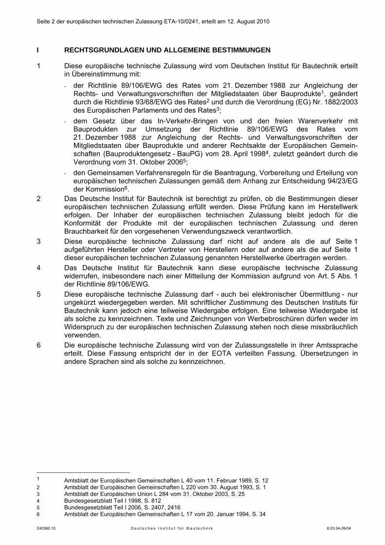
I RECHTSGRUNDLAGEN UND ALLGEMEINE BESTIMMUNGEN
1 Diese europäische technische Zulassung wird vom Deutschen Institut für Bautechnik erteilt in Übereinstimmung mit: - der Richtlinie 89/106/EWG des Rates vom 21. Dezember 1988 zur Angleichung der
Rechts- und Verwaltungsvorschriften der Mitgliedstaaten über Bauprodukte1, geändert durch die Richtlinie 93/68/EWG des Rates2 und durch die Verordnung (EG) Nr. 1882/2003 des Europäischen Parlaments und des Rates3;
- dem Gesetz über das In-Verkehr-Bringen von und den freien Warenverkehr mit Bauprodukten zur Umsetzung der Richtlinie 89/106/EWG des Rates vom 21. Dezember 1988 zur Angleichung der Rechts- und Verwaltungsvorschriften der Mitgliedstaaten über Bauprodukte und anderer Rechtsakte der Europäischen Gemein-schaften (Bauproduktengesetz - BauPG) vom 28. April 19984, zuletzt geändert durch die Verordnung vom 31. Oktober 20065;
- den Gemeinsamen Verfahrensregeln für die Beantragung, Vorbereitung und Erteilung von europäischen technischen Zulassungen gemäß dem Anhang zur Entscheidung 94/23/EG der Kommission6.
2 Das Deutsche Institut für Bautechnik ist berechtigt zu prüfen, ob die Bestimmungen dieser europäischen technischen Zulassung erfüllt werden. Diese Prüfung kann im Herstellwerk erfolgen. Der Inhaber der europäischen technischen Zulassung bleibt jedoch für die Konformität der Produkte mit der europäischen technischen Zulassung und deren Brauchbarkeit für den vorgesehenen Verwendungszweck verantwortlich.
3 Diese europäische technische Zulassung darf nicht auf andere als die auf Seite 1 aufgeführten Hersteller oder Vertreter von Herstellern oder auf andere als die auf Seite 1 dieser europäischen technischen Zulassung genannten Herstellwerke übertragen werden.
4 Das Deutsche Institut für Bautechnik kann diese europäische technische Zulassung widerrufen, insbesondere nach einer Mitteilung der Kommission aufgrund von Art. 5 Abs. 1 der Richtlinie 89/106/EWG.
5 Diese europäische technische Zulassung darf - auch bei elektronischer Übermittlung - nur ungekürzt wiedergegeben werden. Mit schriftlicher Zustimmung des Deutschen Instituts für Bautechnik kann jedoch eine teilweise Wiedergabe erfolgen. Eine teilweise Wiedergabe ist als solche zu kennzeichnen. Texte und Zeichnungen von Werbebroschüren dürfen weder im Widerspruch zu der europäischen technischen Zulassung stehen noch diese missbräuchlich verwenden.
6 Die europäische technische Zulassung wird von der Zulassungsstelle in ihrer Amtssprache erteilt. Diese Fassung entspricht der in der EOTA verteilten Fassung. Übersetzungen in andere Sprachen sind als solche zu kennzeichnen.
1 Amtsblatt der Europäischen Gemeinschaften L 40 vom 11. Februar 1989, S. 12 2 Amtsblatt der Europäischen Gemeinschaften L 220 vom 30. August 1993, S. 1 3 Amtsblatt der Europäischen Union L 284 vom 31. Oktober 2003, S. 25 4 Bundesgesetzblatt Teil I 1998, S. 812 5 Bundesgesetzblatt Teil I 2006, S. 2407, 2416 6 Amtsblatt der Europäischen Gemeinschaften L 17 vom 20. Januar 1994, S. 34
Seite 3 der europäischen technischen Zulassung ETA-10/0241, erteilt am 12. August 2010
Z40360.10 D e u t s c h e s I n s t i t u t f ü r B a u t e c h n i k 8.03.04-26/04
II BESONDERE BESTIMMUNGEN DER EUROPÄISCHEN TECHNISCHEN ZULASSUNG
1 Beschreibung des Produkts und des Verwendungszwecks
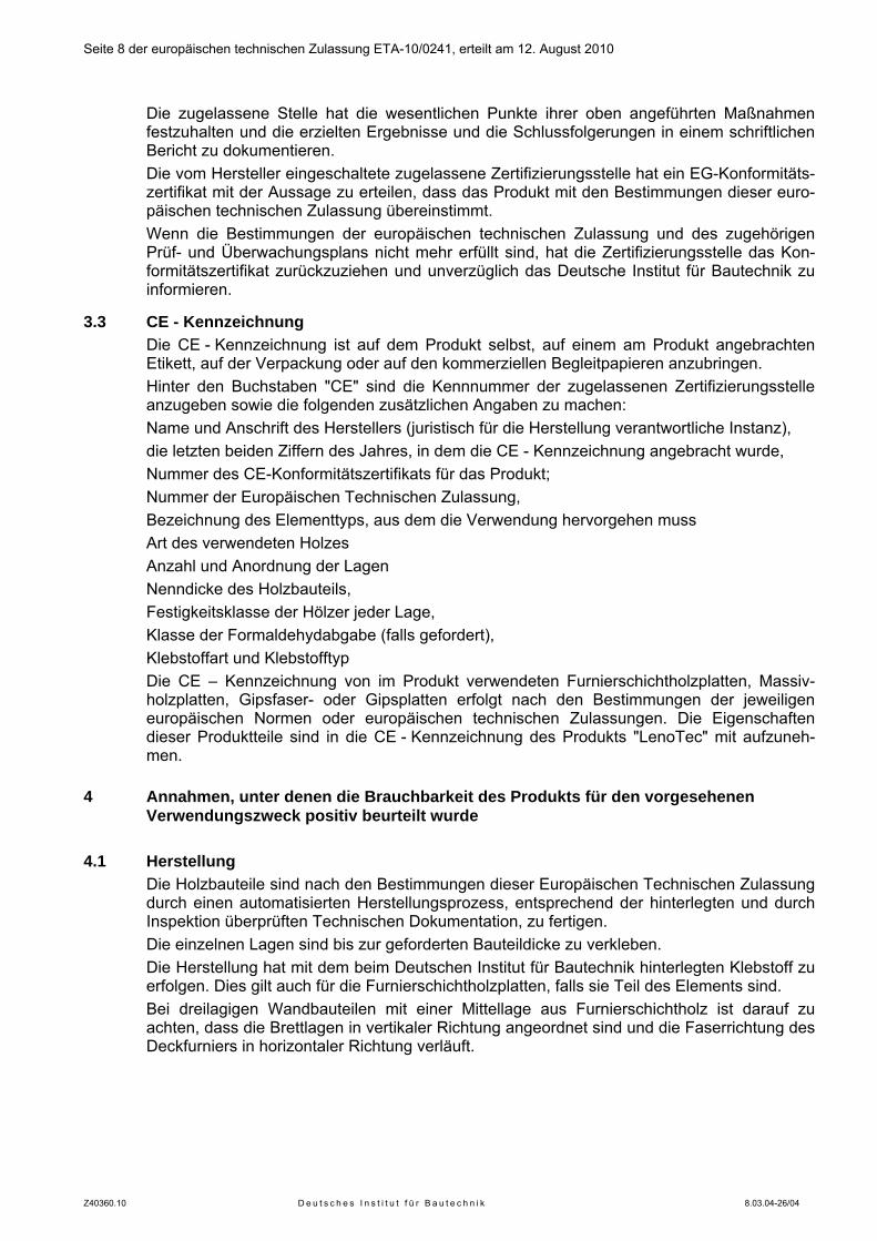
1.1 Beschreibung des Bauprodukts LenoTec sind flächige Holzbauteile aus mindestens drei kreuzweise verklebten Brettlagen
aus Nadelholz. Benachbarte Lagen sind unter einem Winkel von 90° miteinander verklebt. Der Querschnitt der Bauteile ist symmetrisch bzw. weicht geringfügig von der Symmetrie ab.
Der prinzipielle Aufbau des Bauteils ist in Anhang 1 gezeigt. Details zu den zulässigen Auf-bauten sind Abschnitt 2.1.2 zu entnehmen.
Bis zu drei benachbarte Lagen können faserparallel verklebt sein, solange ein annähernd symmetrischer, kreuzweise gesperrter Aufbau erhalten bleibt.
Die Bauteile sind eben. Sie können auch leicht gekrümmt sein, solange diese Krümmung nicht die Eigenschaften der Elemente beeinflusst, die in dieser Europäischen Technischen Zulassung geregelt sind.
Die Decklagen der Elemente dürfen einseitig oder beidseitig durch Massivholzplatten oder Furnierschichtholzplatten ersetzt sein. Bei dreilagigen Bauteilen darf die Mittellage aus Furnierschichtholz bestehen.
Die Holzbauteile können einseitig oder beidseitig durch Gipskartonplatten oder Gipsfaser-platten verstärkt sein. Diese Lagen dürfen beim Nachweis der Tragfähigkeit nicht angesetzt werden.
Die Anwendung chemischer Substanzen (Holzschutzmittel und Brandschutzmittel) in diesen Bauteilen ist nicht Gegenstand dieser Europäischen Technischen Zulassung
1.2 Verwendungszweck Die Holzbauelemente sind für eine Verwendung als tragende, aussteifende oder nicht-
tragende Elemente in Gebäuden oder Holzbauwerken vorgesehen. Die Anwendung darf nur in Bauwerken mit vorwiegend ruhenden Verkehrslasten erfolgen.
Die Elemente sind für eine Verwendung in den Nutzungsklassen 1 und 2 nach EN 1995-1-1 vorgesehen.
Die Bestimmungen dieser Europäischen Technischen Zulassung beruhen auf einer ange-nommenen Nutzungsdauer der Holzbauteile von 50 Jahren, vorausgesetzt, dass die in den Abschnitten 4.2 und 5 festgelegten Bedingungen für den Transport, die Lagerung, den Ein-bau, die Verwendung, die Wartung und die Instandsetzung erfüllt sind. Die Angaben über die Nutzungsdauer können nicht als Garantie des Herstellers ausgelegt werden, sondern sind lediglich als Hilfsmittel zur Auswahl der richtigen Produkte im Hinblick auf die erwartete wirtschaftlich angemessene Nutzungsdauer des Bauwerks zu betrachten.
2 Merkmale des Bauprodukts und Nachweisverfahren
2.1 Merkmale des Bauprodukts und seiner Teile 2.1.1 Allgemeines Die Merkmale des Bauprodukts und seiner Teile sind den Anhängen 1 bis 3 dieser Euro-
päischen Technischen Zulassung zu entnehmen. Details zu den Holzbauteilen sind beim Deutschen Institut für Bautechnik hinterlegt.
2.1.2 Aufbau der Holzbauteile Angaben zum Aufbau der Elemente und zu den zu verwendenden Brettern sind in den An-
hängen 1 und 2 angegeben. Die Bretter werden visuell oder maschinell sortiert. Nur technisch getrocknetes Holz ist zu
verwenden.
Seite 4 der europäischen technischen Zulassung ETA-10/0241, erteilt am 12. August 2010
Z40360.10 D e u t s c h e s I n s t i t u t f ü r B a u t e c h n i k 8.03.04-26/04
Nur beidseitig gehobelte Bretter sind zu verwenden. Die Bretter der einzelnen Lagen dürfen durch Keilzinkenverbindungen nach EN 3857 in Längsrichtung verbunden werden. Stumpf-stöße sind nicht zulässig.
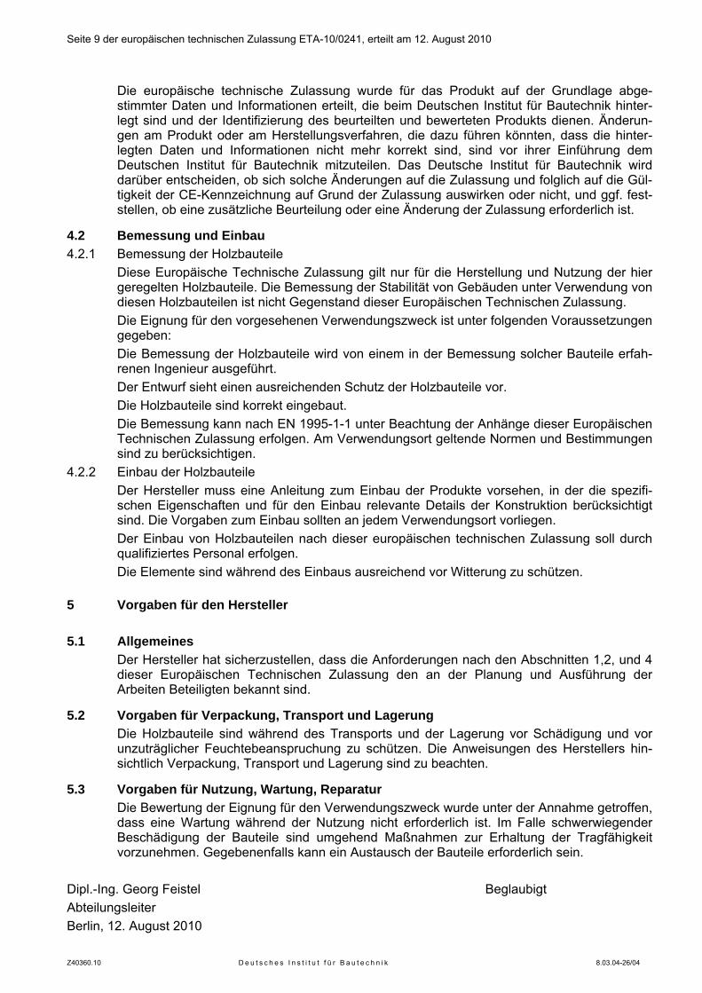
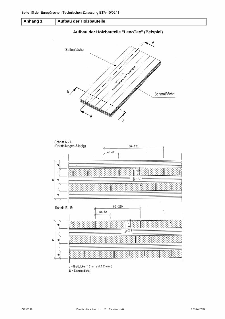
Die Elemente können durch Universal-Keilzinkenstöße nach EN 3878 verbunden sein. In die Einzelbretter dürfen im Abstand von 40 bis 80 mm in Faserrichtung Nuten von ca.
2,5 mm Dicke eingesägt werden. Bei dreilagigen Elementen dürfen anstelle der Nuten Aus-fräsungen mit einer Breite von 20 mm oder 40 mm entsprechend Anlage 2 angeordnet werden. Der Abstand der Nuten und Ausfräsungen vom Rand und untereinander muss zwischen 40 und 80 mm betragen. Die verbleibende Restdicke der Bretter im Bereich der Nuten und Einfräsungen muss zwischen 4 mm und 7 mm betragen.
Die einzelnen Bretter einer Lage werden an ihren Längsseiten nicht verklebt. Die zulässige Fugenbreite ist in Anhang 2 angegeben.
Falls Furnierschichtholzplatten als Decklagen oder, bei dreilagigen Elementen, als mittlere Lage verwendet werden, müssen diese den Anforderungen der EN 143749 und den beim Deutschen Institut für Bautechnik hinterlegten Angaben entsprechen.
Falls Massivholzplatten verwendet werden, müssen diese den Anforderungen der EN 1398610 oder einer Europäischen Technischen Zulassung entsprechen.
Die Furnierschichtholzplatten und Massivholzplatten dürfen maximal eine Dicke von 33 mm haben.
Falls Gipsfaser- oder Gipsplatten als zusätzliche Bekleidung verwendet werden, müssen diese den Anforderungen der EN 52011, der EN 15283-212 oder einer Europäischen Technischen Zulassung entsprechen. Die Gipsfaser- und Gipsplatten dürfen nicht zum Nachweis der Tragfähigkeit angesetzt werden.
Die Furnierschichtholzplatten, Massivholzplatten, Gipsfaser- und Gipsplatten sind lediglich Bestandteile des Produkts LenoTec. Sie sind nicht eigenständig in dieser ETA geregelt. Für Ihre Verwendung sind ggf. nationale Bestimmungen zu beachten.
Der Querschnitt muss symmetrisch aufgebaut sein. Bei konstruktionsbedingten Abweichun-gen von der Symmetrie darf der Abstand der Spannungsnulllinie von der geometrischen Mitte des Querschnitts maximal 1/10 der Bauteildicke betragen.
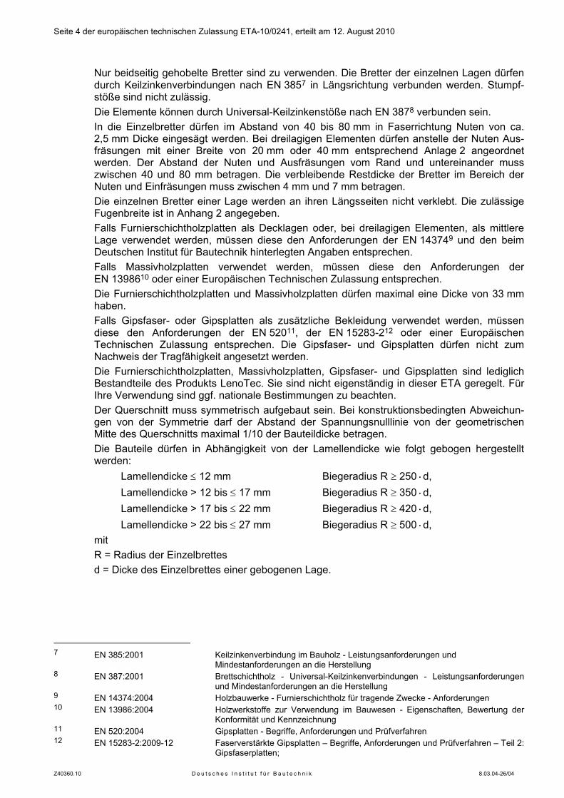
Die Bauteile dürfen in Abhängigkeit von der Lamellendicke wie folgt gebogen hergestellt werden:
Lamellendicke ≤ 12 mm Biegeradius R ≥ 250·d, Lamellendicke > 12 bis ≤ 17 mm Biegeradius R ≥ 350·d, Lamellendicke > 17 bis ≤ 22 mm Biegeradius R ≥ 420·d, Lamellendicke > 22 bis ≤ 27 mm Biegeradius R ≥ 500·d, mit R = Radius der Einzelbrettes d = Dicke des Einzelbrettes einer gebogenen Lage.
7 EN 385:2001 Keilzinkenverbindung im Bauholz - Leistungsanforderungen und
Mindestanforderungen an die Herstellung 8 EN 387:2001 Brettschichtholz - Universal-Keilzinkenverbindungen - Leistungsanforderungen
und Mindestanforderungen an die Herstellung 9 EN 14374:2004 Holzbauwerke - Furnierschichtholz für tragende Zwecke - Anforderungen 10 EN 13986:2004 Holzwerkstoffe zur Verwendung im Bauwesen - Eigenschaften, Bewertung der
Konformität und Kennzeichnung 11 EN 520:2004 Gipsplatten - Begriffe, Anforderungen und Prüfverfahren 12 EN 15283-2:2009-12 Faserverstärkte Gipsplatten – Begriffe, Anforderungen und Prüfverfahren – Teil 2:
Gipsfaserplatten;
Seite 5 der europäischen technischen Zulassung ETA-10/0241, erteilt am 12. August 2010
Z40360.10 D e u t s c h e s I n s t i t u t f ü r B a u t e c h n i k 8.03.04-26/04
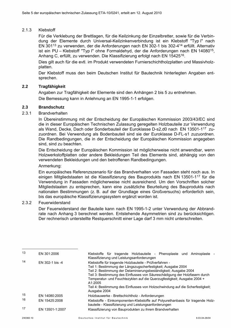
2.1.3 Klebstoff Für die Verklebung der Brettlagen, für die Keilzinkung der Einzelbretter, sowie für die Verbin-
dung der Elemente durch Universal-Keilzinkenverbindung ist ein Klebstoff "Typ I" nach EN 30113 zu verwenden, der die Anforderungen nach EN 302-1 bis 302-414 erfüllt. Alternativ ist ein PU – Klebstoff "Typ I" ohne Formaldehyd, der die Anforderungen nach EN 1408015, Anhang C, erfüllt, zu verwenden. Die Klassifizierung erfolgt nach EN 1542516.
Dies gilt auch für die evtl. im Produkt verwendeten Furnierschichtholzplatten und Massivholz-platten.
Der Klebstoff muss den beim Deutschen Institut für Bautechnik hinterlegten Angaben ent-sprechen.
2.2 Tragfähigkeit Angaben zur Tragfähigkeit der Elemente sind den Anhängen 2 bis 5 zu entnehmen. Die Bemessung kann in Anlehnung an EN 1995-1-1 erfolgen.
2.3 Brandschutz 2.3.1 Brandverhalten In Übereinstimmung mit der Entscheidung der Europäischen Kommission 2003/43/EC sind
die in dieser Europäischen Technischen Zulassung geregelten Holzbauteile zur Verwendung als Wand, Decke, Dach oder Sonderbauteil der Euroklasse D-s2,d0 nach EN 13501-117 zu-zuordnen. Bei Verwendung als Bodenbauteil sind sie der Euroklasse D-FL-s1 zuzuordnen. Die Randbedingungen, die in der Entscheidung der Europäischen Kommission angegeben sind, sind zu beachten.
Die Entscheidung der Europäischen Kommission ist möglicherweise nicht anwendbar, wenn Holzwerkstoffplatten oder andere Bekleidungen Teil des Elements sind, abhängig von den verwendeten Bekleidungen und den betroffenen Randbedingungen.
Anmerkung: Ein europäisches Referenzszenario für das Brandverhalten von Fassaden steht noch aus. In
einigen Mitgliedstaaten ist die Klassifizierung des Bauprodukts nach EN 13501-117 für die Verwendung in Fassaden möglicherweise nicht ausreichend. Um den Vorschriften solcher Mitgliedstaaten zu entsprechen, kann eine zusätzliche Beurteilung des Bauprodukts nach nationalen Bestimmungen (z. B. auf der Grundlage eines Großversuchs) erforderlich sein, bis das europäische Klassifizierungssystem ergänzt worden ist.
2.3.2 Feuerwiderstand Der Feuerwiderstand der Bauteile kann nach EN 1995-1-2 unter Verwendung der Abbrand-
rate nach Anhang 3 berechnet werden. Entstehende Asymmetrien sind zu berücksichtigen. Der rechnerisch unterstellte Restquerschnitt einer Lage darf 3 mm nicht unterschreiten.
13 EN 301:2006 Klebstoffe für tragende Holzbauteile - Phenoplaste und Aminoplaste -
Klassifizierung und Leistungsanforderungen 14 EN 302-1 bis -4 Klebstoffe für tragende Holzbauteile - Prüfverfahren -
Teil 1: Bestimmung der Längszugscherfestigkeit; Ausgabe 2004 Teil 2: Bestimmung der Delaminierungsbeständigkeit; Ausgabe 2004 Teil 3: Bestimmung des Einflusses von Säureschädigung der Holzfasern durch Temperatur- und Feuchtezyklen auf die Querzugfestigkeit; Ausgabe 2004 + A1:2005 Teil 4: Bestimmung des Einflusses von Holzschwindung auf die Scherfestigkeit; Ausgabe 2004
15 EN 14080:2005 Holzbauwerke - Brettschichtholz - Anforderungen 16 EN 15425:2008 Klebstoffe - Einkomponenten-Klebstoffe auf Polyurethanbasis für tragende Holz-
bauteile - Klassifizierung und Leistungsanforderungen 17 EN 13501-1:2007 Klassifizierung von Bauprodukten zu ihrem Brandverhalten
Seite 6 der europäischen technischen Zulassung ETA-10/0241, erteilt am 12. August 2010
Z40360.10 D e u t s c h e s I n s t i t u t f ü r B a u t e c h n i k 8.03.04-26/04
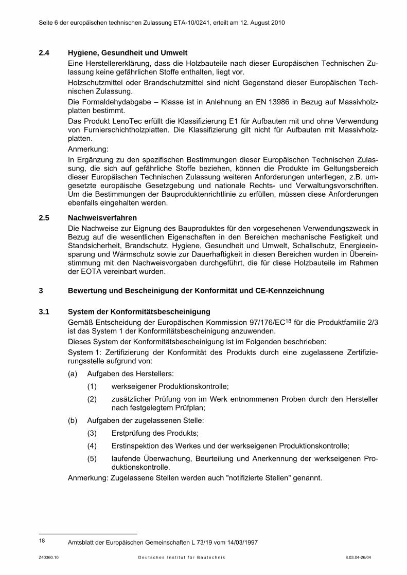
2.4 Hygiene, Gesundheit und Umwelt Eine Herstellererklärung, dass die Holzbauteile nach dieser Europäischen Technischen Zu-
lassung keine gefährlichen Stoffe enthalten, liegt vor. Holzschutzmittel oder Brandschutzmittel sind nicht Gegenstand dieser Europäischen Tech-
nischen Zulassung. Die Formaldehydabgabe – Klasse ist in Anlehnung an EN 13986 in Bezug auf Massivholz-
platten bestimmt. Das Produkt LenoTec erfüllt die Klassifizierung E1 für Aufbauten mit und ohne Verwendung
von Furnierschichtholzplatten. Die Klassifizierung gilt nicht für Aufbauten mit Massivholz-platten.
Anmerkung: In Ergänzung zu den spezifischen Bestimmungen dieser Europäischen Technischen Zulas-
sung, die sich auf gefährliche Stoffe beziehen, können die Produkte im Geltungsbereich dieser Europäischen Technischen Zulassung weiteren Anforderungen unterliegen, z.B. um-gesetzte europäische Gesetzgebung und nationale Rechts- und Verwaltungsvorschriften. Um die Bestimmungen der Bauproduktenrichtlinie zu erfüllen, müssen diese Anforderungen ebenfalls eingehalten werden.
2.5 Nachweisverfahren Die Nachweise zur Eignung des Bauproduktes für den vorgesehenen Verwendungszweck in
Bezug auf die wesentlichen Eigenschaften in den Bereichen mechanische Festigkeit und Standsicherheit, Brandschutz, Hygiene, Gesundheit und Umwelt, Schallschutz, Energieein-sparung und Wärmschutz sowie zur Dauerhaftigkeit in diesen Bereichen wurden in Überein-stimmung mit den Nachweisvorgaben durchgeführt, die für diese Holzbauteile im Rahmen der EOTA vereinbart wurden.
3 Bewertung und Bescheinigung der Konformität und CE-Kennzeichnung
3.1 System der Konformitätsbescheinigung Gemäß Entscheidung der Europäischen Kommission 97/176/EC18 für die Produktfamilie 2/3
ist das System 1 der Konformitätsbescheinigung anzuwenden. Dieses System der Konformitätsbescheinigung ist im Folgenden beschrieben: System 1: Zertifizierung der Konformität des Produkts durch eine zugelassene Zertifizie-
rungsstelle aufgrund von:
(a) Aufgaben des Herstellers:
(1) werkseigener Produktionskontrolle;
(2) zusätzlicher Prüfung von im Werk entnommenen Proben durch den Hersteller nach festgelegtem Prüfplan;
(b) Aufgaben der zugelassenen Stelle:
(3) Erstprüfung des Produkts;
(4) Erstinspektion des Werkes und der werkseigenen Produktionskontrolle;
(5) laufende Überwachung, Beurteilung und Anerkennung der werkseigenen Pro-duktionskontrolle.
Anmerkung: Zugelassene Stellen werden auch "notifizierte Stellen" genannt.
18 Amtsblatt der Europäischen Gemeinschaften L 73/19 vom 14/03/1997
Seite 7 der europäischen technischen Zulassung ETA-10/0241, erteilt am 12. August 2010
Z40360.10 D e u t s c h e s I n s t i t u t f ü r B a u t e c h n i k 8.03.04-26/04
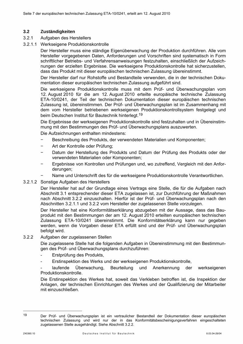
3.2 Zuständigkeiten 3.2.1 Aufgaben des Herstellers 3.2.1.1 Werkseigene Produktionskontrolle Der Hersteller muss eine ständige Eigenüberwachung der Produktion durchführen. Alle vom
Hersteller vorgegebenen Daten, Anforderungen und Vorschriften sind systematisch in Form schriftlicher Betriebs- und Verfahrensanweisungen festzuhalten, einschließlich der Aufzeich-nungen der erzielten Ergebnisse. Die werkseigene Produktionskontrolle hat sicherzustellen, dass das Produkt mit dieser europäischen technischen Zulassung übereinstimmt.
Der Hersteller darf nur Rohstoffe und Bestandteile verwenden, die in der technischen Doku-mentation dieser europäischen technischen Zulassung aufgeführt sind.
Die werkseigene Produktionskontrolle muss mit dem Prüf- und Überwachungsplan vom 12. August 2010 für die am 12. August 2010 erteilte europäische technische Zulassung ETA-10/0241, der Teil der technischen Dokumentation dieser europäischen technischen Zulassung ist, übereinstimmen. Der Prüf- und Überwachungsplan ist im Zusammenhang mit dem vom Hersteller betriebenen werkseigenen Produktionskontrollsystem festgelegt und beim Deutschen Institut für Bautechnik hinterlegt.19
Die Ergebnisse der werkseigenen Produktionskontrolle sind festzuhalten und in Übereinstim-mung mit den Bestimmungen des Prüf- und Überwachungsplans auszuwerten.
Die Aufzeichnungen enthalten mindestens: − Beschreibung des Produkts, der verwendeten Materialien und Komponenten; − Art der Kontrolle oder Prüfung; − Datum der Herstellung des Produkts und Datum der Prüfung des Produkts oder der
verwendeten Materialien oder Komponenten; − Ergebnisse von Kontrollen und Prüfungen und, wo zutreffend, Vergleich mit den Anfor-
derungen; − Name und Unterschrift des für die werkseigene Produktionskontrolle Verantwortlichen.
3.2.1.2 Sonstige Aufgaben des Herstellers Der Hersteller hat auf der Grundlage eines Vertrags eine Stelle, die für die Aufgaben nach
Abschnitt 3.1 entsprechender dieser ETA zugelassen ist, zur Durchführung der Maßnahmen nach Abschnitt 3.2.2 einzuschalten. Hierfür ist der Prüf- und Überwachungsplan nach den Abschnitten 3.2.1.1 und 3.2.2 vom Hersteller der zugelassenen Stelle vorzulegen.
Der Hersteller hat eine Konformitätserklärung abzugeben mit der Aussage, dass das Bau-produkt mit den Bestimmungen der am 12. August 2010 erteilten europäischen technischen Zulassung ETA-10/0241 übereinstimmt. Die Konformitätserklärung kann nur gegeben werden, wenn die Vorgaben dieser ETA erfüllt sind und der Prüf- und Überwachungsplan befolgt wird.
3.2.2 Aufgaben der zugelassenen Stellen Die zugelassene Stelle hat die folgenden Aufgaben in Übereinstimmung mit den Bestimmun-
gen des Prüf- und Überwachungsplans durchzuführen: - Erstprüfung des Produkts, - Erstinspektion des Werks und der werkseigenen Produktionskontrolle, - laufende Überwachung, Beurteilung und Anerkennung der werkseigenen Produktionskontrolle. Die Erstinspektion des Werkes hat, soweit das Verkleben betroffen ist, die Inspektion der Anlagen, der technischen Einrichtungen des Werkes und der Qualifizierung der Mitarbeiter mit einzuschließen.
19 Der Prüf- und Überwachungsplan ist ein vertraulicher Bestandteil der Dokumentation dieser europäischen
technischen Zulassung und wird nur der in das Konformitätsbescheinigungsverfahren eingeschalteten zugelassenen Stelle ausgehändigt. Siehe Abschnitt 3.2.2.
Seite 8 der europäischen technischen Zulassung ETA-10/0241, erteilt am 12. August 2010
Z40360.10 D e u t s c h e s I n s t i t u t f ü r B a u t e c h n i k 8.03.04-26/04
Die zugelassene Stelle hat die wesentlichen Punkte ihrer oben angeführten Maßnahmen festzuhalten und die erzielten Ergebnisse und die Schlussfolgerungen in einem schriftlichen Bericht zu dokumentieren.
Die vom Hersteller eingeschaltete zugelassene Zertifizierungsstelle hat ein EG-Konformitäts-zertifikat mit der Aussage zu erteilen, dass das Produkt mit den Bestimmungen dieser euro-päischen technischen Zulassung übereinstimmt.
Wenn die Bestimmungen der europäischen technischen Zulassung und des zugehörigen Prüf- und Überwachungsplans nicht mehr erfüllt sind, hat die Zertifizierungsstelle das Kon-formitätszertifikat zurückzuziehen und unverzüglich das Deutsche Institut für Bautechnik zu informieren.
3.3 CE - Kennzeichnung Die CE - Kennzeichnung ist auf dem Produkt selbst, auf einem am Produkt angebrachten
Etikett, auf der Verpackung oder auf den kommerziellen Begleitpapieren anzubringen. Hinter den Buchstaben "CE" sind die Kennnummer der zugelassenen Zertifizierungsstelle
anzugeben sowie die folgenden zusätzlichen Angaben zu machen: Name und Anschrift des Herstellers (juristisch für die Herstellung verantwortliche Instanz), die letzten beiden Ziffern des Jahres, in dem die CE - Kennzeichnung angebracht wurde, Nummer des CE-Konformitätszertifikats für das Produkt; Nummer der Europäischen Technischen Zulassung, Bezeichnung des Elementtyps, aus dem die Verwendung hervorgehen muss Art des verwendeten Holzes Anzahl und Anordnung der Lagen Nenndicke des Holzbauteils, Festigkeitsklasse der Hölzer jeder Lage, Klasse der Formaldehydabgabe (falls gefordert), Klebstoffart und Klebstofftyp Die CE – Kennzeichnung von im Produkt verwendeten Furnierschichtholzplatten, Massiv-holzplatten, Gipsfaser- oder Gipsplatten erfolgt nach den Bestimmungen der jeweiligen europäischen Normen oder europäischen technischen Zulassungen. Die Eigenschaften dieser Produktteile sind in die CE - Kennzeichnung des Produkts "LenoTec" mit aufzuneh-men.
4 Annahmen, unter denen die Brauchbarkeit des Produkts für den vorgesehenen Verwendungszweck positiv beurteilt wurde
4.1 Herstellung Die Holzbauteile sind nach den Bestimmungen dieser Europäischen Technischen Zulassung
durch einen automatisierten Herstellungsprozess, entsprechend der hinterlegten und durch Inspektion überprüften Technischen Dokumentation, zu fertigen.
Die einzelnen Lagen sind bis zur geforderten Bauteildicke zu verkleben. Die Herstellung hat mit dem beim Deutschen Institut für Bautechnik hinterlegten Klebstoff zu
erfolgen. Dies gilt auch für die Furnierschichtholzplatten, falls sie Teil des Elements sind. Bei dreilagigen Wandbauteilen mit einer Mittellage aus Furnierschichtholz ist darauf zu achten, dass die Brettlagen in vertikaler Richtung angeordnet sind und die Faserrichtung des Deckfurniers in horizontaler Richtung verläuft.
Seite 9 der europäischen technischen Zulassung ETA-10/0241, erteilt am 12. August 2010
Z40360.10 D e u t s c h e s I n s t i t u t f ü r B a u t e c h n i k 8.03.04-26/04
Die europäische technische Zulassung wurde für das Produkt auf der Grundlage abge-stimmter Daten und Informationen erteilt, die beim Deutschen Institut für Bautechnik hinter-legt sind und der Identifizierung des beurteilten und bewerteten Produkts dienen. Änderun-gen am Produkt oder am Herstellungsverfahren, die dazu führen könnten, dass die hinter-legten Daten und Informationen nicht mehr korrekt sind, sind vor ihrer Einführung dem Deutschen Institut für Bautechnik mitzuteilen. Das Deutsche Institut für Bautechnik wird darüber entscheiden, ob sich solche Änderungen auf die Zulassung und folglich auf die Gül-tigkeit der CE-Kennzeichnung auf Grund der Zulassung auswirken oder nicht, und ggf. fest-stellen, ob eine zusätzliche Beurteilung oder eine Änderung der Zulassung erforderlich ist.
4.2 Bemessung und Einbau 4.2.1 Bemessung der Holzbauteile Diese Europäische Technische Zulassung gilt nur für die Herstellung und Nutzung der hier
geregelten Holzbauteile. Die Bemessung der Stabilität von Gebäuden unter Verwendung von diesen Holzbauteilen ist nicht Gegenstand dieser Europäischen Technischen Zulassung.
Die Eignung für den vorgesehenen Verwendungszweck ist unter folgenden Voraussetzungen gegeben: Die Bemessung der Holzbauteile wird von einem in der Bemessung solcher Bauteile erfah-renen Ingenieur ausgeführt. Der Entwurf sieht einen ausreichenden Schutz der Holzbauteile vor. Die Holzbauteile sind korrekt eingebaut.
Die Bemessung kann nach EN 1995-1-1 unter Beachtung der Anhänge dieser Europäischen Technischen Zulassung erfolgen. Am Verwendungsort geltende Normen und Bestimmungen sind zu berücksichtigen.
4.2.2 Einbau der Holzbauteile Der Hersteller muss eine Anleitung zum Einbau der Produkte vorsehen, in der die spezifi-
schen Eigenschaften und für den Einbau relevante Details der Konstruktion berücksichtigt sind. Die Vorgaben zum Einbau sollten an jedem Verwendungsort vorliegen.
Der Einbau von Holzbauteilen nach dieser europäischen technischen Zulassung soll durch qualifiziertes Personal erfolgen.
Die Elemente sind während des Einbaus ausreichend vor Witterung zu schützen.
5 Vorgaben für den Hersteller
5.1 Allgemeines Der Hersteller hat sicherzustellen, dass die Anforderungen nach den Abschnitten 1,2, und 4
dieser Europäischen Technischen Zulassung den an der Planung und Ausführung der Arbeiten Beteiligten bekannt sind.
5.2 Vorgaben für Verpackung, Transport und Lagerung Die Holzbauteile sind während des Transports und der Lagerung vor Schädigung und vor
unzuträglicher Feuchtebeanspruchung zu schützen. Die Anweisungen des Herstellers hin-sichtlich Verpackung, Transport und Lagerung sind zu beachten.
5.3 Vorgaben für Nutzung, Wartung, Reparatur Die Bewertung der Eignung für den Verwendungszweck wurde unter der Annahme getroffen,
dass eine Wartung während der Nutzung nicht erforderlich ist. Im Falle schwerwiegender Beschädigung der Bauteile sind umgehend Maßnahmen zur Erhaltung der Tragfähigkeit vorzunehmen. Gegebenenfalls kann ein Austausch der Bauteile erforderlich sein.
Dipl.-Ing. Georg Feistel Beglaubigt Abteilungsleiter Berlin, 12. August 2010
Seite 10 der Europäischen Technischen Zulassung ETA-10/0241 Anhang 1 Aufbau der Holzbauteile
Z40360.10 D e u t s c h e s I n s t i t u t f ü r B a u t e c h n i k 8.03.04-26/04
Aufbau der Holzbauteile "LenoTec" (Beispiel)
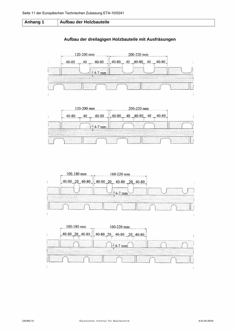
Seite 11 der Europäischen Technischen Zulassung ETA-10/0241 Anhang 1 Aufbau der Holzbauteile
Z40360.10 D e u t s c h e s I n s t i t u t f ü r B a u t e c h n i k 8.03.04-26/04
Aufbau der dreilagigen Holzbauteile mit Ausfräsungen
Seite 12 der Europäischen Technischen Zulassung ETA-10/0241 Anhang 2 Abmessungen und Aufbau der Holzbauteile
Z40360.10 D e u t s c h e s I n s t i t u t f ü r B a u t e c h n i k 8.03.04-26/04
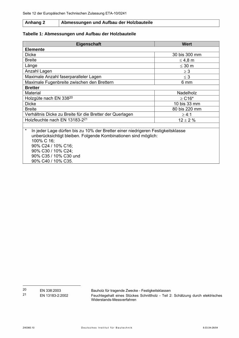
Tabelle 1: Abmessungen und Aufbau der Holzbauteile
Eigenschaft Wert Elemente Dicke 30 bis 300 mm Breite ≤ 4,8 m Länge ≤ 30 m Anzahl Lagen ≥ 3 Maximale Anzahl faserparalleler Lagen ≤ 3 Maximale Fugenbreite zwischen den Brettern 6 mm Bretter Material Nadelholz Holzgüte nach EN 33820 ≥ C16* Dicke 10 bis 33 mm Breite 80 bis 220 mm Verhältnis Dicke zu Breite für die Bretter der Querlagen ≥ 4:1 Holzfeuchte nach EN 13183-221 12 ± 2 %
* In jeder Lage dürfen bis zu 10% der Bretter einer niedrigeren Festigkeitsklasse
unberücksichtigt bleiben. Folgende Kombinationen sind möglich: 100% C 16; 90% C24 / 10% C16; 90% C30 / 10% C24; 90% C35 / 10% C30 und 90% C40 / 10% C35.
20 EN 338:2003 Bauholz für tragende Zwecke - Festigkeitsklassen 21 EN 13183-2:2002 Feuchtegehalt eines Stückes Schnittholz - Teil 2: Schätzung durch elektrisches
Widerstands-Messverfahren
Seite 13 der Europäischen Technischen Zulassung ETA-10/0241 Anhang 3 Hinweise zur Bemessung der Elemente und der Verbindungsmittel
Z40360.10 D e u t s c h e s I n s t i t u t f ü r B a u t e c h n i k 8.03.04-26/04
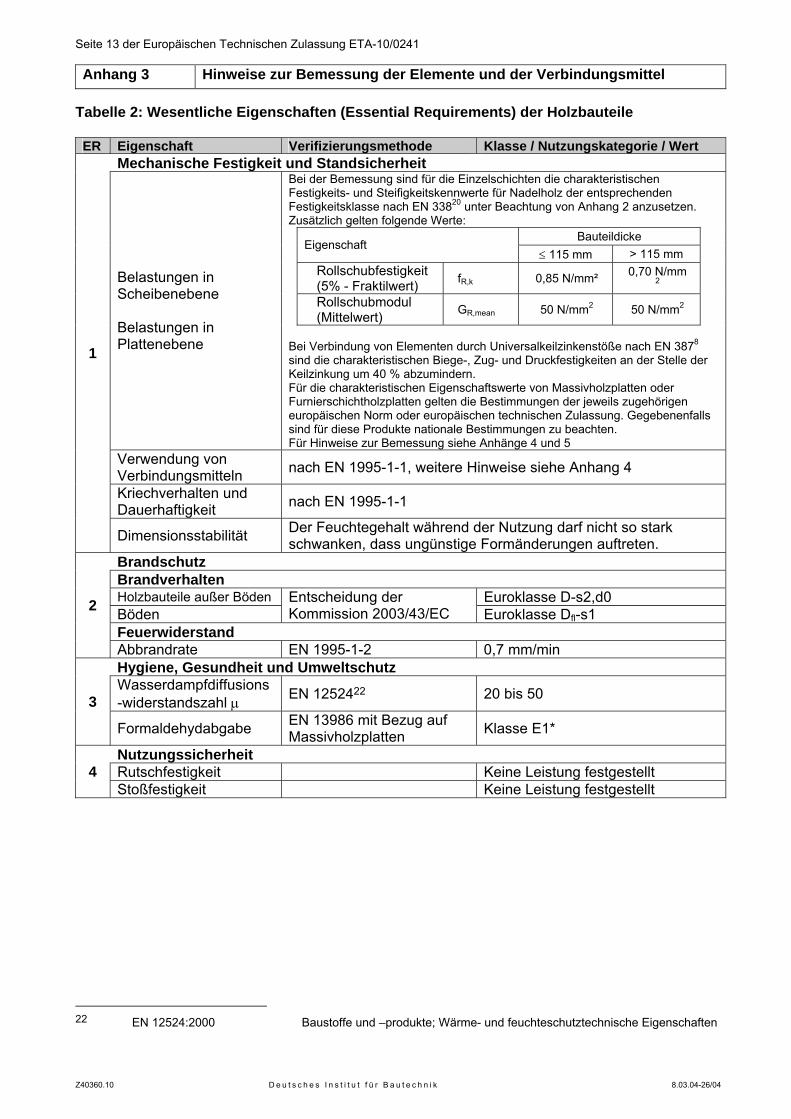
Tabelle 2: Wesentliche Eigenschaften (Essential Requirements) der Holzbauteile ER Eigenschaft Verifizierungsmethode Klasse / Nutzungskategorie / Wert
Mechanische Festigkeit und Standsicherheit Bei der Bemessung sind für die Einzelschichten die charakteristischen Festigkeits- und Steifigkeitskennwerte für Nadelholz der entsprechenden Festigkeitsklasse nach EN 33820 unter Beachtung von Anhang 2 anzusetzen. Zusätzlich gelten folgende Werte: Bauteildicke
Eigenschaft ≤ 115 mm > 115 mm
Rollschubfestigkeit (5% - Fraktilwert) fR,k 0,85 N/mm² 0,70 N/mm
2
Rollschubmodul (Mittelwert) GR,mean 50 N/mm2 50 N/mm2
Belastungen in Scheibenebene Belastungen in Plattenebene
Bei Verbindung von Elementen durch Universalkeilzinkenstöße nach EN 3878 sind die charakteristischen Biege-, Zug- und Druckfestigkeiten an der Stelle der Keilzinkung um 40 % abzumindern. Für die charakteristischen Eigenschaftswerte von Massivholzplatten oder Furnierschichtholzplatten gelten die Bestimmungen der jeweils zugehörigen europäischen Norm oder europäischen technischen Zulassung. Gegebenenfalls sind für diese Produkte nationale Bestimmungen zu beachten. Für Hinweise zur Bemessung siehe Anhänge 4 und 5
Verwendung von Verbindungsmitteln nach EN 1995-1-1, weitere Hinweise siehe Anhang 4
Kriechverhalten und Dauerhaftigkeit nach EN 1995-1-1
1
Dimensionsstabilität Der Feuchtegehalt während der Nutzung darf nicht so stark schwanken, dass ungünstige Formänderungen auftreten.
Brandschutz Brandverhalten Holzbauteile außer Böden Euroklasse D-s2,d0 Böden
Entscheidung der Kommission 2003/43/EC Euroklasse Dfl-s1
Feuerwiderstand
2
Abbrandrate EN 1995-1-2 0,7 mm/min Hygiene, Gesundheit und Umweltschutz Wasserdampfdiffusions-widerstandszahl μ EN 1252422 20 bis 50 3
Formaldehydabgabe EN 13986 mit Bezug auf Massivholzplatten Klasse E1*
Nutzungssicherheit Rutschfestigkeit Keine Leistung festgestellt 4 Stoßfestigkeit Keine Leistung festgestellt
22 EN 12524:2000 Baustoffe und –produkte; Wärme- und feuchteschutztechnische Eigenschaften
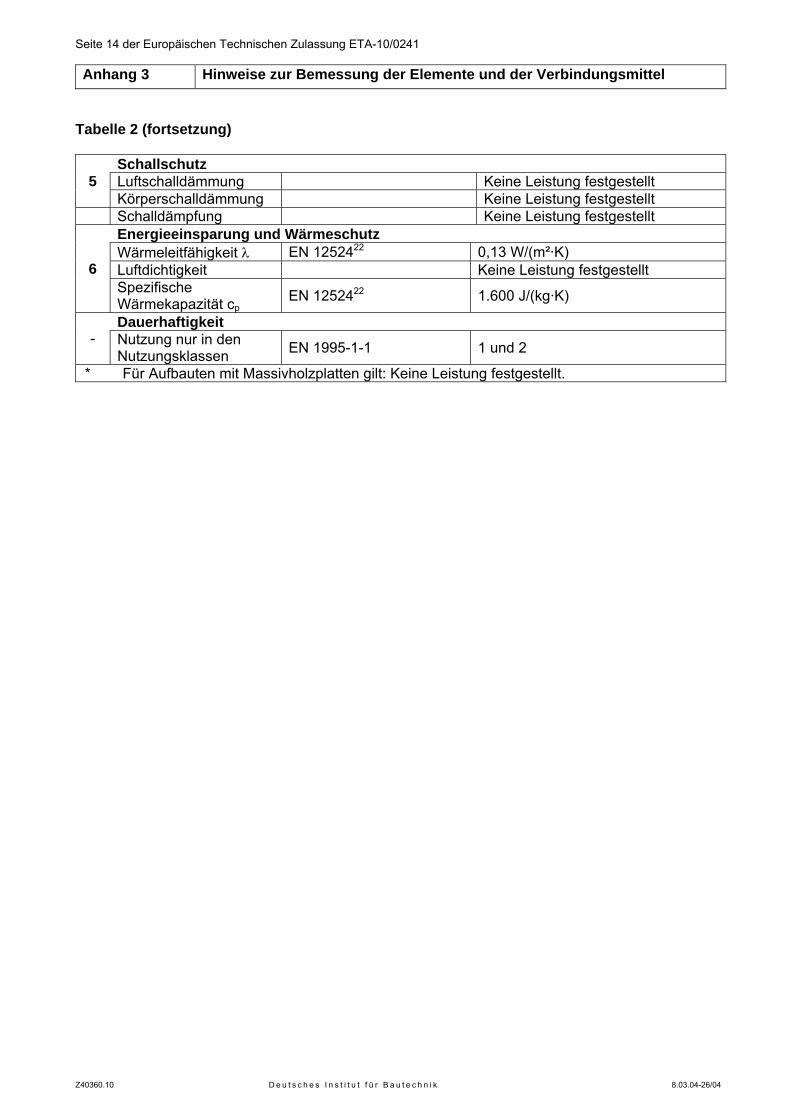
Seite 14 der Europäischen Technischen Zulassung ETA-10/0241 Anhang 3 Hinweise zur Bemessung der Elemente und der Verbindungsmittel
Z40360.10 D e u t s c h e s I n s t i t u t f ü r B a u t e c h n i k 8.03.04-26/04
Tabelle 2 (fortsetzung)
Schallschutz Luftschalldämmung Keine Leistung festgestellt 5 Körperschalldämmung Keine Leistung festgestellt
Schalldämpfung Keine Leistung festgestellt Energieeinsparung und Wärmeschutz Wärmeleitfähigkeit λ EN 1252422 0,13 W/(m²·K) Luftdichtigkeit Keine Leistung festgestellt 6 Spezifische Wärmekapazität cp
EN 1252422 1.600 J/(kg·K)
Dauerhaftigkeit - Nutzung nur in den
Nutzungsklassen EN 1995-1-1 1 und 2
* Für Aufbauten mit Massivholzplatten gilt: Keine Leistung festgestellt.
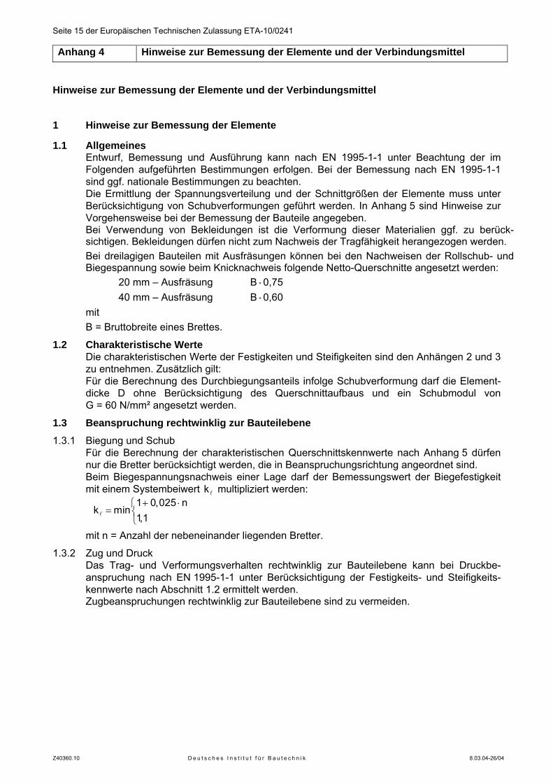
Seite 15 der Europäischen Technischen Zulassung ETA-10/0241 Anhang 4 Hinweise zur Bemessung der Elemente und der Verbindungsmittel
Z40360.10 D e u t s c h e s I n s t i t u t f ü r B a u t e c h n i k 8.03.04-26/04
Hinweise zur Bemessung der Elemente und der Verbindungsmittel 1 Hinweise zur Bemessung der Elemente
1.1 Allgemeines Entwurf, Bemessung und Ausführung kann nach EN 1995-1-1 unter Beachtung der im Folgenden aufgeführten Bestimmungen erfolgen. Bei der Bemessung nach EN 1995-1-1 sind ggf. nationale Bestimmungen zu beachten. Die Ermittlung der Spannungsverteilung und der Schnittgrößen der Elemente muss unter Berücksichtigung von Schubverformungen geführt werden. In Anhang 5 sind Hinweise zur Vorgehensweise bei der Bemessung der Bauteile angegeben. Bei Verwendung von Bekleidungen ist die Verformung dieser Materialien ggf. zu berück-sichtigen. Bekleidungen dürfen nicht zum Nachweis der Tragfähigkeit herangezogen werden. Bei dreilagigen Bauteilen mit Ausfräsungen können bei den Nachweisen der Rollschub- und Biegespannung sowie beim Knicknachweis folgende Netto-Querschnitte angesetzt werden: 20 mm – Ausfräsung B·0,75 40 mm – Ausfräsung B·0,60 mit B = Bruttobreite eines Brettes.
1.2 Charakteristische Werte Die charakteristischen Werte der Festigkeiten und Steifigkeiten sind den Anhängen 2 und 3 zu entnehmen. Zusätzlich gilt: Für die Berechnung des Durchbiegungsanteils infolge Schubverformung darf die Element-dicke D ohne Berücksichtigung des Querschnittaufbaus und ein Schubmodul von G = 60 N/mm² angesetzt werden.
1.3 Beanspruchung rechtwinklig zur Bauteilebene 1.3.1 Biegung und Schub
Für die Berechnung der charakteristischen Querschnittskennwerte nach Anhang 5 dürfen nur die Bretter berücksichtigt werden, die in Beanspruchungsrichtung angeordnet sind. Beim Biegespannungsnachweis einer Lage darf der Bemessungswert der Biegefestigkeit mit einem Systembeiwert lk multipliziert werden:
+ ⋅⎧
= ⎨⎩
l
1 0,025 nk min
1,1
mit n = Anzahl der nebeneinander liegenden Bretter.
1.3.2 Zug und Druck Das Trag- und Verformungsverhalten rechtwinklig zur Bauteilebene kann bei Druckbe-anspruchung nach EN 1995-1-1 unter Berücksichtigung der Festigkeits- und Steifigkeits-kennwerte nach Abschnitt 1.2 ermittelt werden.
Zugbeanspruchungen rechtwinklig zur Bauteilebene sind zu vermeiden.
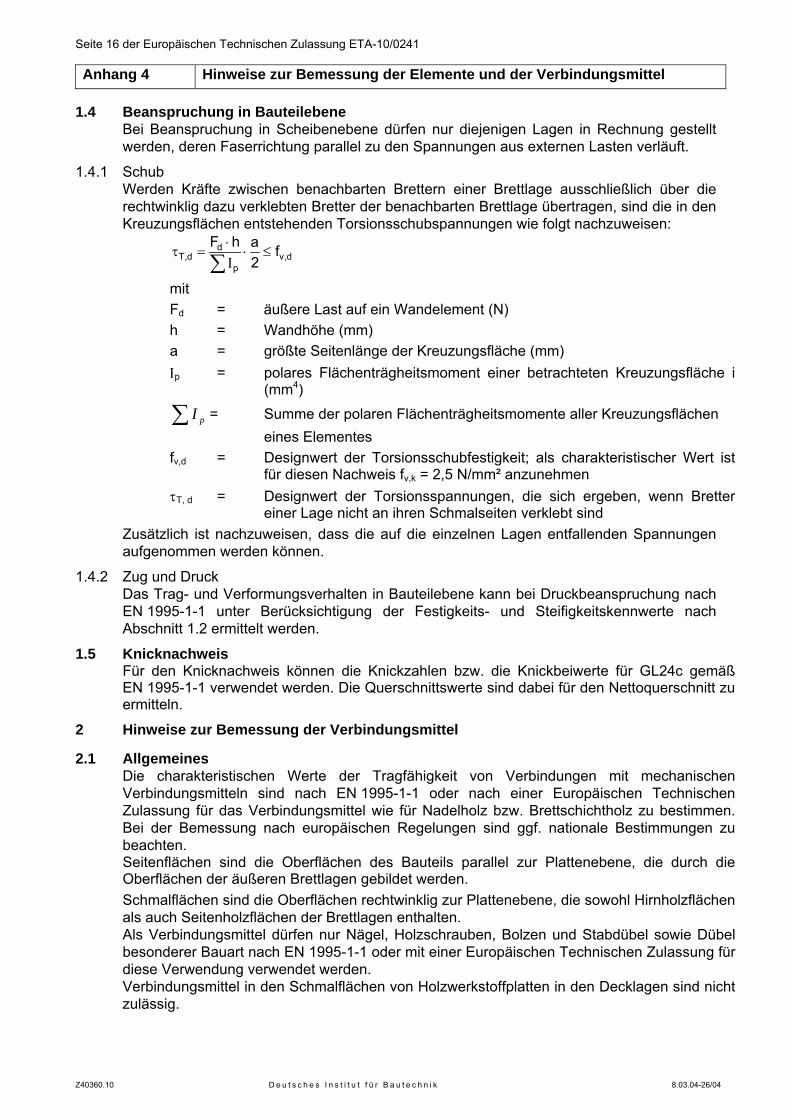
Seite 16 der Europäischen Technischen Zulassung ETA-10/0241 Anhang 4 Hinweise zur Bemessung der Elemente und der Verbindungsmittel
Z40360.10 D e u t s c h e s I n s t i t u t f ü r B a u t e c h n i k 8.03.04-26/04
1.4 Beanspruchung in Bauteilebene Bei Beanspruchung in Scheibenebene dürfen nur diejenigen Lagen in Rechnung gestellt werden, deren Faserrichtung parallel zu den Spannungen aus externen Lasten verläuft.
1.4.1 Schub Werden Kräfte zwischen benachbarten Brettern einer Brettlage ausschließlich über die rechtwinklig dazu verklebten Bretter der benachbarten Brettlage übertragen, sind die in den Kreuzungsflächen entstehenden Torsionsschubspannungen wie folgt nachzuweisen:
dT,d v,d
p
F h a f2
⋅τ = ⋅ ≤
Ι∑
mit Fd = äußere Last auf ein Wandelement (N) h = Wandhöhe (mm) a = größte Seitenlänge der Kreuzungsfläche (mm) Ιp = polares Flächenträgheitsmoment einer betrachteten Kreuzungsfläche i
(mm4)
∑ pI = Summe der polaren Flächenträgheitsmomente aller Kreuzungsflächen eines Elementes
fv,d = Designwert der Torsionsschubfestigkeit; als charakteristischer Wert ist für diesen Nachweis fv,k = 2,5 N/mm² anzunehmen
τT, d = Designwert der Torsionsspannungen, die sich ergeben, wenn Bretter einer Lage nicht an ihren Schmalseiten verklebt sind
Zusätzlich ist nachzuweisen, dass die auf die einzelnen Lagen entfallenden Spannungen aufgenommen werden können.
1.4.2 Zug und Druck Das Trag- und Verformungsverhalten in Bauteilebene kann bei Druckbeanspruchung nach EN 1995-1-1 unter Berücksichtigung der Festigkeits- und Steifigkeitskennwerte nach Abschnitt 1.2 ermittelt werden.
1.5 Knicknachweis Für den Knicknachweis können die Knickzahlen bzw. die Knickbeiwerte für GL24c gemäß EN 1995-1-1 verwendet werden. Die Querschnittswerte sind dabei für den Nettoquerschnitt zu ermitteln.
2 Hinweise zur Bemessung der Verbindungsmittel
2.1 Allgemeines Die charakteristischen Werte der Tragfähigkeit von Verbindungen mit mechanischen Verbindungsmitteln sind nach EN 1995-1-1 oder nach einer Europäischen Technischen Zulassung für das Verbindungsmittel wie für Nadelholz bzw. Brettschichtholz zu bestimmen. Bei der Bemessung nach europäischen Regelungen sind ggf. nationale Bestimmungen zu beachten. Seitenflächen sind die Oberflächen des Bauteils parallel zur Plattenebene, die durch die Oberflächen der äußeren Brettlagen gebildet werden. Schmalflächen sind die Oberflächen rechtwinklig zur Plattenebene, die sowohl Hirnholzflächen als auch Seitenholzflächen der Brettlagen enthalten. Als Verbindungsmittel dürfen nur Nägel, Holzschrauben, Bolzen und Stabdübel sowie Dübel besonderer Bauart nach EN 1995-1-1 oder mit einer Europäischen Technischen Zulassung für diese Verwendung verwendet werden. Verbindungsmittel in den Schmalflächen von Holzwerkstoffplatten in den Decklagen sind nicht zulässig.
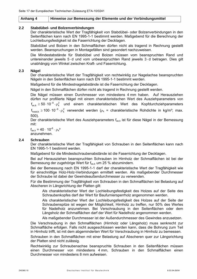
Seite 17 der Europäischen Technischen Zulassung ETA-10/0241 Anhang 4 Hinweise zur Bemessung der Elemente und der Verbindungsmittel
Z40360.10 D e u t s c h e s I n s t i t u t f ü r B a u t e c h n i k 8.03.04-26/04
2.2 Stabdübel- und Bolzenverbindungen Der charakteristische Wert der Tragfähigkeit von Stabdübel- oder Bolzenverbindungen in den Seitenflächen kann nach EN 1995-1-1 bestimmt werden. Maßgebend für die Berechnung der Lochleibungsfestigkeit ist die Faserrichtung der Decklagen. Stabdübel und Bolzen in den Schmalflächen dürfen nicht als tragend in Rechnung gestellt werden. Beanspruchungen in Montagefällen sind gesondert nachzuweisen. Die Mindestabstände für Stabdübel und Bolzen müssen vom beanspruchten Rand und untereinander jeweils 5·d und vom unbeanspruchten Rand jeweils 3·d betragen. Dies gilt unabhängig vom Winkel zwischen Kraft- und Faserrichtung.
2.3 Nägel Der charakteristische Wert der Tragfähigkeit von rechtwinklig zur Nagelachse beanspruchten Nägeln in den Seitenflächen kann nach EN 1995-1-1 bestimmt werden. Maßgebend für die Mindestnagelabstände ist die Faserrichtung der Decklagen. Nägel in den Schmalflächen dürfen nicht als tragend in Rechnung gestellt werden. Die Nägel müssen einen Durchmesser von mindestens 4 mm haben. Auf Herausziehen dürfen nur profilierte Nägel mit einem charakteristischen Wert des Ausziehparameters von
2k
6k,ax 1050f ρ⋅⋅≥ − und einem charakteristischen Wert des Kopfdurchziehparameters
2k
6k,head 10100f ρ⋅⋅≥ − verwendet werden (ρk = charakteristische Rohdichte in kg/m³; max.
500). Der charakteristische Wert des Ausziehparameters fax,k ist für diese Nägel in der Bemessung mit:
fax,k = 40 ⋅ 10-6 ⋅ ρk² anzunehmen.
2.4 Schrauben Der charakteristische Wert der Tragfähigkeit von Schrauben in den Seitenflächen kann nach EN 1995-1-1 bestimmt werden. Maßgebend für die Mindestschraubenabstände ist die Faserrichtung der Decklagen. Bei auf Herausziehen beanspruchten Schrauben im Hirnholz der Schmalflächen ist bei der Bemessung der zugehörige Wert für fax,k um 25 % abzumindern. Bei der Bemessung nach EN 1995-1-1 darf der charakteristische Wert der Tragfähigkeit wie für einschnittige Holz-Holz-Verbindungen ermittelt werden. Als maßgebender Durchmesser der Schraube ist dabei der Gewindeaußendurchmesser zu verwenden. Für die Bestimmung der Tragfähigkeit von Schrauben in den Schmalflächen bei Belastung auf Abscheren in Längsrichtung der Platten gilt:
Als charakteristischer Wert der Lochleibungsfestigkeit des Holzes auf der Seite des Schraubenkopfes darf der Wert für Baufurniersperrholz angenommen werden. Als charakteristischer Wert der Lochleibungsfestigkeit des Holzes auf der Seite der Schraubenspitze ist wegen der Möglichkeit, Hirnholz zu treffen, nur 50% des Wertes für Nadelholz anzunehmen. Bei Verschraubung in den Seitenflächen oder dem Längsholz der Schmalflächen darf der Wert für Nadelholz angenommen werden. Als maßgebender Durchmesser ist der Außendurchmesser des Gewindes anzusetzen.
Die Verschraubung in den Schmalflächen (Hirnholz oder Längsholz) muss senkrecht zur Schmalfläche erfolgen. Falls nicht ausgeschlossen werden kann, dass die Bohrung zum Teil in Hirnholz trifft, ist mit dem abgeminderten Wert für Verschraubung in Hirnholz zu bemessen. Schrauben in den Schmalflächen mit einer Belastung auf Abscheren quer zur Längsrichtung der Platten sind nicht zulässig. Rechtwinklig zur Schraubenachse beanspruchte Schrauben in den Seitenflächen müssen einen Durchmesser von mindestens 4 mm, Schrauben in den Schmalflächen einen Durchmesser von mindestens 8 mm aufweisen.
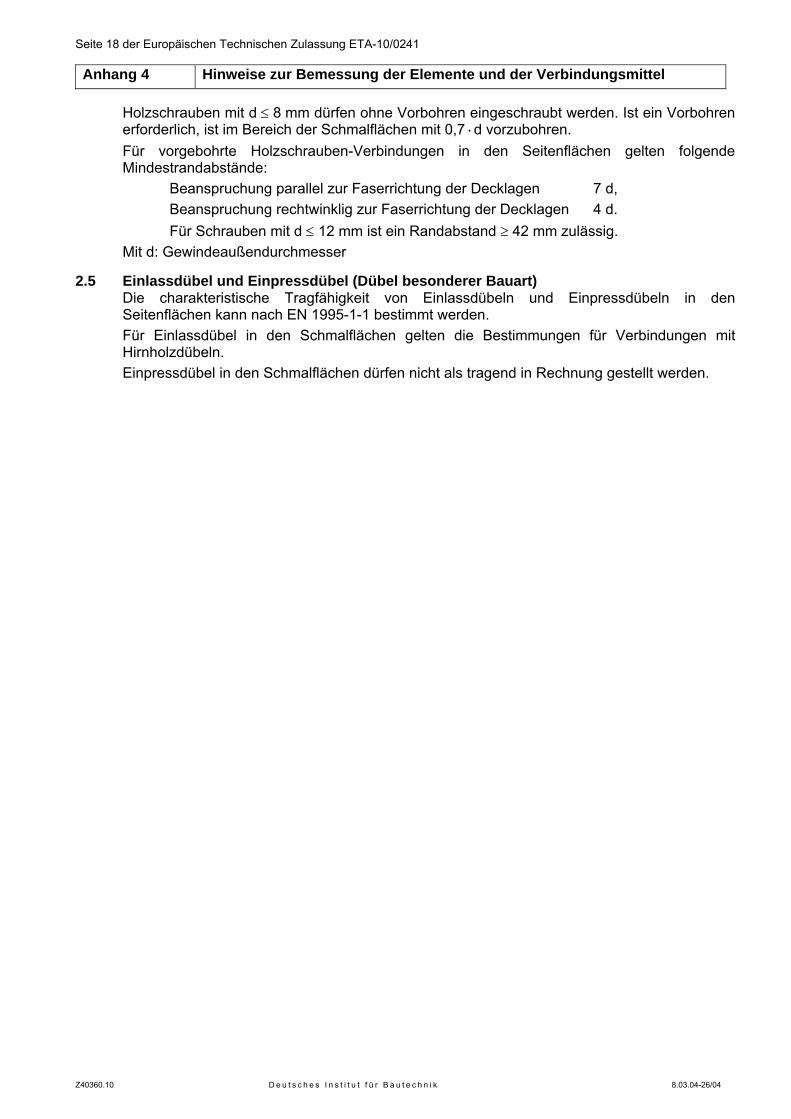
Seite 18 der Europäischen Technischen Zulassung ETA-10/0241 Anhang 4 Hinweise zur Bemessung der Elemente und der Verbindungsmittel
Z40360.10 D e u t s c h e s I n s t i t u t f ü r B a u t e c h n i k 8.03.04-26/04
Holzschrauben mit d ≤ 8 mm dürfen ohne Vorbohren eingeschraubt werden. Ist ein Vorbohren erforderlich, ist im Bereich der Schmalflächen mit 0,7·d vorzubohren. Für vorgebohrte Holzschrauben-Verbindungen in den Seitenflächen gelten folgende Mindestrandabstände:
Beanspruchung parallel zur Faserrichtung der Decklagen 7 d, Beanspruchung rechtwinklig zur Faserrichtung der Decklagen 4 d. Für Schrauben mit d ≤ 12 mm ist ein Randabstand ≥ 42 mm zulässig.
Mit d: Gewindeaußendurchmesser
2.5 Einlassdübel und Einpressdübel (Dübel besonderer Bauart) Die charakteristische Tragfähigkeit von Einlassdübeln und Einpressdübeln in den Seitenflächen kann nach EN 1995-1-1 bestimmt werden. Für Einlassdübel in den Schmalflächen gelten die Bestimmungen für Verbindungen mit Hirnholzdübeln. Einpressdübel in den Schmalflächen dürfen nicht als tragend in Rechnung gestellt werden.
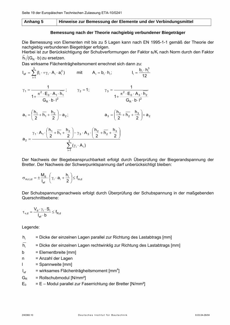
Seite 19 der Europäischen Technischen Zulassung ETA-10/0241 Anhang 5 Hinweise zur Bemessung der Elemente und der Verbindungsmittel
Z40360.10 D e u t s c h e s I n s t i t u t f ü r B a u t e c h n i k 8.03.04-26/04
Bemessung nach der Theorie nachgiebig verbundener Biegeträger Die Bemessung von Elementen mit bis zu 5 Lagen kann nach EN 1995-1-1 gemäß der Theorie der nachgiebig verbundenen Biegeträger erfolgen. Hierbei ist zur Berücksichtigung der Schubverformungen der Faktor si/Ki nach Norm durch den Faktor
)bG(h Ri ⋅ zu ersetzen. Das wirksame Flächenträgheitsmoment errechnet sich dann zu:
∑=
⋅⋅γ+⋅=3
1i
2iiiief )aAI(I mit iii hbA ⋅= ;
12hbI
3ii
i⋅
=
2R
11021
lbGhAE
1
1
⋅⋅
⋅⋅⋅π+
=γ ; 12 =γ ;
2R
23023
lbGhAE
1
1
⋅⋅
⋅⋅⋅π+
=γ
22
11
1 a2
hh
2h
a −⎟⎠
⎞⎜⎝
⎛++= ; 2
32
23 a
2h
h2
ha +⎟⎟
⎠
⎞⎜⎜⎝
⎛++=
∑=
⋅γ
⎟⎟⎠
⎞⎜⎜⎝
⎛++⋅⋅γ−⎟
⎠
⎞⎜⎝
⎛++⋅⋅γ
= 3
1iii
32
233
21
111
2
)A(
2h
h2
hA
2h
h2h
Aa
Der Nachweis der Biegebeanspruchbarkeit erfolgt durch Überprüfung der Biegerandspannung der Bretter. Der Nachweis der Schwerpunktspannung darf unberücksichtigt bleiben:
d,mi
iief
dd,i,r,m f
2ha
IM
≤⎟⎠
⎞⎜⎝
⎛ +⋅γ⋅±=σ
Der Schubspannungsnachweis erfolgt durch Überprüfung der Schubspannung in der maßgebenden Querschnittsebene:
d,Ref
iidd,v f
bISV
≤⋅⋅γ⋅
=τ
Legende:
ih = Dicke der einzelnen Lagen parallel zur Richtung des Lastabtrags [mm]
ih = Dicke der einzelnen Lagen rechtwinklig zur Richtung des Lastabtrags [mm] b = Elementbreite [mm] n = Anzahl der Lagen l = Spannweite [mm]
efI = wirksames Flächenträgheitsmoment [mm4] GR = Rollschubmodul [N/mm²] E0 = E – Modul parallel zur Faserrichtung der Bretter [N/mm²]
Diese Zulassung umfasst
This Approval contains
19 Seiten einschließlich 5 Anhänge 19 pages including 5 annexes
E u r o p ä i s c h e O r g a n i s a t i o n f ü r T e c h n i s c h e Z u l a s s u n g e n
E u r o p e a n O r g a n i s a t i o n f o r T e c h n i c a l A p p r o v a l s
Deutsches Institut für Bautechnik Anstalt des öffentlichen Rechts
Kolonnenstr. 30 L 10829 Berlin Germany
Tel.: +49(0)30 787 30 0 Fax: +49(0)30 787 30 320 E-mail: [email protected] Internet: www.dibt.de
Mitglied der EOTA Member of EOTA
European Technical Approval ETA-10/0241
English translation prepared by DIBt - Original version in German language
Handelsbezeichnung Trade name
LenoTec LenoTec
Zulassungsinhaber
Holder of approval Finnforest Merk GmbH Industriestraße 2 86551 Aichach
Zulassungsgegenstand und Verwendungszweck
Massive plattenförmige Holzbauelemente zur Verwendung als tragende Teile in Bauwerken
Generic type and use of construction product
Solid wood slab elements to be used as structural elements in buildings Geltungsdauer:
Validity: vom from
12 August 2010
bis to
12 August 2015
Herstellwerk
Manufacturing plant Finnforest Merk GmbH Industriestraße 2 86551 Aichach DEUTSCHLAND
Page 2 of ETA-10/0241, issued on 12 August 2010 English translation by Deutsches Institut für Bautechnik (DIBt)
Z25256.10 D e u t s c h e s I n s t i t u t f ü r B a u t e c h n i k 8.03.04-26/04
I LEGAL BASES AND GENERAL CONDITIONS
1 This European technical approval is issued by Deutsches Institut für Bautechnik in accordance with: - Council Directive 89/106/EEC of 21 December 1988 on the approximation of laws,
regulations and administrative provisions of Member States relating to construction products1, modified by Council Directive 93/68/EEC2 and Regulation (EC) N° 1882/2003 of the European Parliament and of the Council3;
- Gesetz über das In-Verkehr-Bringen von und den freien Warenverkehr mit Bauprodukten zur Umsetzung der Richtlinie 89/106/EWG des Rates vom 21. Dezember 1988 zur Angleichung der Rechts- und Verwaltungsvorschriften der Mitgliedstaaten über Bauprodukte und anderer Rechtsakte der Europäischen Gemeinschaften (Bauprodukten-gesetz - BauPG) vom 28. April 19984, as amended by law of 31 October 20065;
- Common Procedural Rules for Requesting, Preparing and the Granting of European technical approvals set out in the Annex to Commission Decision 94/23/EC6.
2 Deutsches Institut für Bautechnik is authorized to check whether the provisions of this European technical approval are met. Checking may take place in the manufacturing plant. Nevertheless, the responsibility for the conformity of the products to the European technical approval and for their fitness for the intended use remains with the holder of the European technical approval.
3 This European technical approval is not to be transferred to manufacturers or agents of manufacturers other than those indicated on page 1, or manufacturing plants other than those indicated on page 1 of this European technical approval.
4 This European technical approval may be withdrawn by Deutsches Institut für Bautechnik, in particular pursuant to information by the Commission according to Article 5(1) of Council Directive 89/106/EEC.
5 Reproduction of this European technical approval including transmission by electronic means shall be in full. However, partial reproduction can be made with the written consent of Deutsches Institut für Bautechnik. In this case partial reproduction has to be designated as such. Texts and drawings of advertising brochures shall not contradict or misuse the European technical approval.
6 The European technical approval is issued by the approval body in its official language. This version corresponds fully to the version circulated within EOTA. Translations into other languages have to be designated as such.
1 Official Journal of the European Communities L 40, 11 February 1989, p. 12 2 Official Journal of the European Communities L 220, 30 August 1993, p. 1 3 Official Journal of the European Union L 284, 31 October 2003, p. 25 4 Bundesgesetzblatt Teil I 1998, p. 812 5 Bundesgesetzblatt Teil I 2006, p.2407, 2416 6 Official Journal of the European Communities L 17, 20 January 1994, p. 34
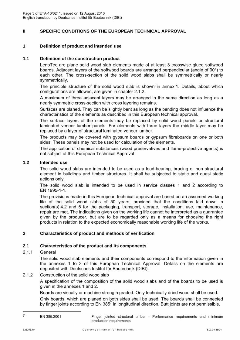
Page 3 of ETA-10/0241, issued on 12 August 2010 English translation by Deutsches Institut für Bautechnik (DIBt)
Z25256.10 D e u t s c h e s I n s t i t u t f ü r B a u t e c h n i k 8.03.04-26/04
II SPECIFIC CONDITIONS OF THE EUROPEAN TECHNICAL APPROVAL
1 Definition of product and intended use
1.1 Definition of the construction product LenoTec are plane solid wood slab elements made of at least 3 crosswise glued softwood
boards. Adjacent layers of the softwood boards are arranged perpendicular (angle of 90°) to each other. The cross-section of the solid wood slabs shall be symmetrically or nearly symmetrically.
The principle structure of the solid wood slab is shown in annex 1. Details, about which configurations are allowed, are given in chapter 2.1.2.
A maximum of three adjacent layers may be arranged in the same direction as long as a nearly symmetric cross-section with cross layering remains.
Surfaces are planed. They can be slightly bent as long as the bending does not influence the characteristics of the elements as described in this European technical approval.
The surface layers of the elements may be replaced by solid wood panels or structural laminated veneer lumber panels. For elements with three layers the middle layer may be replaced by a layer of structural laminated veneer lumber.
The products may be covered with gypsum boards or gypsum fibreboards on one or both sides. These panels may not be used for calculation of the elements.
The application of chemical substances (wood preservatives and flame-protective agents) is not subject of this European Technical Approval.
1.2 Intended use The solid wood slabs are intended to be used as a load-bearing, bracing or non structural
element in buildings and timber structures. It shall be subjected to static and quasi static actions only.
The solid wood slab is intended to be used in service classes 1 and 2 according to EN 1995-1-1.
The provisions made in this European technical approval are based on an assumed working life of the solid wood slabs of 50 years, provided that the conditions laid down in section(s) 4.2 and 5 for the packaging, transport, storage, installation, use, maintenance, repair are met. The indications given on the working life cannot be interpreted as a guarantee given by the producer, but are to be regarded only as a means for choosing the right products in relation to the expected economically reasonable working life of the works.
2 Characteristics of product and methods of verification
2.1 Characteristics of the product and its components 2.1.1 General The solid wood slab elements and their components correspond to the information given in
the annexes 1 to 3 of this European Technical Approval. Details on the elements are deposited with Deutsches Institut für Bautechnik (DIBt).
2.1.2 Construction of the solid wood slab A specification of the composition of the solid wood slabs and of the boards to be used is
given in the annexes 1 and 2. Boards are visually or machine strength graded. Only technically dried wood shall be used. Only boards, which are planed on both sides shall be used. The boards shall be connected
by finger joints according to EN 3857 in longitudinal direction. Butt joints are not permissible. 7 EN 385:2001 Finger jointed structural timber - Performance requirements and minimum
production requirements
Page 4 of ETA-10/0241, issued on 12 August 2010 English translation by Deutsches Institut für Bautechnik (DIBt)
Z25256.10 D e u t s c h e s I n s t i t u t f ü r B a u t e c h n i k 8.03.04-26/04
The elements can be connected by universal finger joints according to EN 3878. The boards can be grooved with notches of approx. 2,5 mm width in intervals of 40 to
80 mm. For elements of three layers notches with a width of 20 mm or 40 mm according to annex 2 are allowed. The distance between the notches and between notch and edge must be between 40 m and 80 mm. The remaining thickness of the board in field of the notches must be between 4 mm and 7 mm.
The boards within a layer are not glued together on their adjacent surfaces. The acceptable width of gaps is given in annex 2.
If structural laminated veneer lumber is used as surface layer or, for elements with three layers, as middle layer, it must fulfil the requirements as stated in EN 143749 and as deposited with Deutsches Institut für Bautechnik.
If solid wood panels are used, they must fulfil the requirements as stated in EN 1398610 or in a European technical approval.
The structural laminated veneer lumber and the solid wood panels shall have a maximum thickness of 33 mm.
If gypsum boards or gypsum fibre boards are used as additional layer, they must fulfil the requirements as stated in EN 52011, EN 15283-212 or a European technical approval. The gypsum boards or gypsum fibre boards might not be taken into account for calculation.
The laminated veneer lumber, the solid wood panels, the gypsum plaster boards and gypsum fibre boards are only components of the product "LenoTec". They are not regulated independently in this European technical approval. National regulations might have to be followed for their use.
The cross section shall be symmetric. In case of deviances from the symmetry the distance between the stresses neutral line and the geometrical middle of the cross section shall not be more than 1/10 of the thickness of the element.
The elements might be bent depending on the thickness of the layers as follows: Thickness of the layer ≤ 12 mm bending radius R ≥ 250·d, Thickness of the layer > 12 bis ≤ 17 mm bending radius R ≥ 350·d, Thickness of the layer > 17 bis ≤ 22 mm bending radius R ≥ 420·d, Thickness of the layer > 22 bis ≤ 27 mm bending radius R ≥ 500·d, with R = bending radius of a single board d = thickness of a single board of a bended layer.
8 EN 387:2001 Glued laminated timber - Large finger joints - Performance requirements and
minimum production requirements 9 EN 14374:2004 Timber structures - Structural laminated veneer lumber - Requirements 10 EN 13986:2004 Wood-based panels for use in construction - Characteristics, evaluation of
conformity and marking 11 EN 520:2004 Gipsplatten - Begriffe, Anforderungen und Prüfverfahren 12 EN 15283-2:2009 Gypsum boards with fibrous reinforcement – Definitions, requirements and test
methods – Part 2: Gypsum fibre boards
Page 5 of ETA-10/0241, issued on 12 August 2010 English translation by Deutsches Institut für Bautechnik (DIBt)
Z25256.10 D e u t s c h e s I n s t i t u t f ü r B a u t e c h n i k 8.03.04-26/04
2.1.3 Adhesive The adhesive for gluing the layers, the finger joints of the individual boards and the universal
finger joints shall be an adhesive "Type I" conform to EN 30113 which passed the tests according to EN 302-1 to EN 302-414. Alternatively a PU – adhesive fulfilling the requirements of EN 1408015, Annex C, might be used. For the classification EN 1542516 applies.
This also applies for solid wood panels and laminated veneer lumber being part of the product.
The adhesive used must be conform to the information deposited with Deutsches Institut für Bautechnik.
2.2 Mechanical resistance and stability The specifications regarding mechanical resistance and stability are given in annexes 2 to 5.
Design can be carried out according to EN 1995-1-1.
2.3 Behaviour in case of fire 2.3.1 Reaction to fire In accordance with Commission Decision 2003/43/EC the solid wood slab elements covered
by this European technical approval for use as wall, roof, ceiling and special construction components comply with Euroclass D-s2,d0 according to EN 13501-117. For the use as floor construction components they comply with Euroclass DFL-s1. The boundary conditions stated in the commission decision have to be attended for this classification.
The Decision of the European Commission might not apply if additional layers are part of the element, depending on the additional layers used and the boundary conditions affected.
Note: A European reference fire scenario for façades has not been laid down. In some Member
States, the classification of the solid wood slabs according to EN 13501-117 might not be sufficient for the use in façades. An additional assessment of the solid wood slabs according to national provisions (e.g. on the basis of a large scale test) might be necessary to comply with Member State regulations, until the existing European classification system has been completed.
2.3.2 Resistance to fire The resistance to fire performance can be calculated according to EN 1995-1-2 using the
charring rate given in annex 3. Occurring asymmetries have to be taken into account. The remaining cross section might not be thinner than 3 mm.
13 EN 301:2006 Adhesives, phenolic and aminoplastic, for load-bearing timber structures -
Classification and performance requirements 14 EN 302-1 to -4 Adhesives for load-bearing timber structures - Test methods -
Part 1: Determination of bond strength in longitudinal tensile shear strength; 2004 Part 2: Determination of resistance to delamination; 2004 Adhesives for load-bearing timber structures - Test methods - Part 3: Determination of the effect of acid damage to wood fibres by temperature and humidity cycling on the transverse tensile strength; 2004 + A1:2005 Adhesives for load-bearing timber structures - Test methods - Part 4: Determination of the effects of wood shrinkage on the shear strength; 2004
15 EN 14080:2005 Timber structures - Glued laminated timber - Requirements 16 EN 15425:2008 Adhesives - One component polyurethane for load bearing timber structures -
Classification and performance requirements 17 EN 13501-1:2007 Fire classification of construction products and building elements - Classification
using data from reaction to fire tests
Page 6 of ETA-10/0241, issued on 12 August 2010 English translation by Deutsches Institut für Bautechnik (DIBt)
Z25256.10 D e u t s c h e s I n s t i t u t f ü r B a u t e c h n i k 8.03.04-26/04
2.4 Hygiene, health and the environment A manufacturer’s declaration has been submitted that no dangerous substances are used in
the product regulated by this European technical approval. Wood preservatives or flame retardants are not part of this European Technical Approval. The class of release of formaldehyde has been determined according to EN 13986 with
regard to solid wood panels. The product Lenotec fulfils the classification E1 for assemblies with and without laminated
veneer lumber. For assemblies with solid wood panels "no performance determined" applies. Note: In addition to the specific clauses relating to dangerous substances contained in this
European technical approval, there may be other requirements applicable to the products falling within its scope (e.g. transposed European legislation and national laws, regulations and administrative provisions). In order to meet the provisions of the Construction Products Directive, these requirements need also to be complied with, when and where they apply.
2.5 Methods of verification The assessment of the fitness of the solid wood slab for the intended use in relation to the
requirements for mechanical resistance and stability, for safety in case of fire, for hygiene, health and the environment, for protection against noise, for energy economy and heat retention, as well as for durability in the sense of these Essential has been made in compliance with the assessment rules for solid wood slabs agreed upon within EOTA.
3 Evaluation and attestation of conformity and CE marking
3.1 System of attestation of conformity According to the Decision 97/176/EC18 of the European Commission for the product family
2/3 system 1 of the attestation of conformity applies. This system of attestation of conformity is defined as follows:
System 1: Certification of the conformity of the product by an approved certification body on the basis of:
(a) Tasks for the manufacturer: (1) factory production control; (2) further testing of samples taken at the factory by the manufacturer in accordance
with a prescribed test plan; (b) Tasks for the approved body:
(3) initial type–testing of the product; (4) initial inspection of factory and of factory production control; (5) continuous surveillance, assessment and approval of factory production control.
Note: Approved bodies are also referred to as "notified bodies".
18 Official Journal of the European Communities L 73/19 from 03/1997
Page 7 of ETA-10/0241, issued on 12 August 2010 English translation by Deutsches Institut für Bautechnik (DIBt)
Z25256.10 D e u t s c h e s I n s t i t u t f ü r B a u t e c h n i k 8.03.04-26/04
3.2 Responsibilities 3.2.1 Tasks for the manufacturer 3.2.1.1 Factory production control The manufacturer shall exercise permanent internal control of production. All the elements,
requirements and provisions adopted by the manufacturer shall be documented in a systematic manner in the form of written policies and procedures, including records of results performed. This production control system shall insure that the product is in conformity with this European technical approval.
The manufacturer may only use constituent materials stated in the technical documentation of this European technical approval.
The factory production control shall be in accordance with the "control plan of 12 August 2010 relating to the European technical approval ETA-10/0241" issued on 12 August 2010 which is part of the technical documentation of this European technical approval. The control plan is laid down in the context of the factory production control system operated by the manufacturer and deposited with Deutsches Institut für Bautechnik.19
The results of factory production control shall be recorded and evaluated in accordance with the provisions of the control plan. The records include at least: − Designation of the product, basic materials and components; − Type of control or testing; − Date of manufacture of the product and date of testing of the product or basic materials or
components; − Results of control and testing and, if appropriate, comparison with requirements; − Name and signature of person responsible for factory production control.
3.2.1.2 Other tasks for the manufacturer The manufacturer shall, on the basis of a contract, involve a body which is approved for the
tasks referred to in section 3.1 in order to undertake the actions laid down in section 3.2.2 For this purpose, the control plan referred to in sections 3.2.1.1 and 3.2.2 shall be handed over by the manufacturer to the approved body involved.
The manufacturer shall make a declaration of conformity, stating that the construction product is in conformity with the provisions of the European technical approval ETA-10/0241 issued on 12 August 2010. The declaration of conformity can only be given if the provisions of this ETA are met and the control plan is being followed.
3.2.2 Tasks for the approved bodies The approved body shall perform the
- initial type-testing of the product, - initial inspection of factory and of factory production control, - continuous surveillance, assessment and approval of factory production
in accordance with the provisions laid down in the control plan. The initial inspection of the factory shall include the inspection of the factory plant, the
technical equipment and the qualification of the staff. The approved body shall retain the essential points of its actions referred to above and state
the results obtained and conclusions drawn in a written report. The approved certification body involved by the manufacturer shall issue an EC certificate of
conformity of the product stating the conformity with the provisions of this European technical approval. The certificate of conformity can only be given if the provisions of this ETA are met and the control plan is being followed.
In cases where the provisions of the European technical approval and its control plan are no longer fulfilled the certification body shall withdraw the certificate of conformity and inform Deutsches Institut für Bautechnik without delay.
19 The "control plan" is a confidential part of the European technical approval and only handed over to the approved
body involved in the procedure of attestation of conformity. See section 3.2.2.
Page 8 of ETA-10/0241, issued on 12 August 2010 English translation by Deutsches Institut für Bautechnik (DIBt)
Z25256.10 D e u t s c h e s I n s t i t u t f ü r B a u t e c h n i k 8.03.04-26/04
3.3 CE marking The CE marking shall be affixed on the product itself, a label attached to it, the packaging or
the accompanying commercial document. The letters ”CE” shall be followed by the identification number of the approved certification
body and shall be accompanied by the following additional information: - the name and address of the producer (legal entity responsible for the manufacture), - the last two digits of the year in which the CE marking was affixed, - the number of the EC certificate of conformity for the product, - the number of the European technical approval, - description of the element, showing its intended use, - species of the wood used, - number and arrangement of the layers, - nominal thickness of the element, - strength class of the wood of each layer - class of release of formaldehyde (if required) - type and classification of the adhesive used For the CE – marking of laminated veneer lumber (LVL), Solid wood panels (SWP), gypsum boards and gypsum fibre boards used within the element the regulations provided in the associated European standards or European Technical Approvals apply. The characteristics of this product parts shall be included in the CE – marking of the product "LenoTec" according to this European Technical Approval.
4 Assumptions under which the fitness of the products for the intended use was favourably assessed
4.1 Manufacturing The solid wood slabs are manufactured in accordance with the provisions of this European
Technical Approval using the automated manufacturing process as identified in the inspection of the plant by the Deutsches Institut für Bautechnik and laid down in the technical documentation.
The layers shall be glued together to the required thickness of the solid wood slabs. The adhesive deposited with Deutsches Institut für Bautechnik shall be used for
manufacturing. This applies also to laminated veneer lumber planes if they are part of the element.
For elements with three layers and a middle layer of laminated veneer lumber it shall be observed that the boards are arranged vertically and the direction of the grain of the surface layers is arranged horizontally.
The European technical approval is issued for the product on the basis of agreed data/information, deposited with Deutsches Institut für Bautechnik, which identifies the product that has been assessed and judged. Changes to the product or production process, which could result in this deposited data/information being incorrect, should be notified to Deutsches Institut für Bautechnik before the changes are introduced. Deutsches Institut für Bautechnik will decide whether or not such changes affect the approval and consequently the validity of the CE marking on the basis of the approval and if so whether further assessment or alterations to the approval shall be necessary.
4.2 Installation 4.2.1 Design of solid wood slab elements The European Technical Approval only applies to the manufacture and use of the solid wood
slab. Verification of stability of the works including application of loads on the solid wood slab is not subject of this European Technical Approval. Fitness for the intended use of the solid wood slab is given under the following conditions:
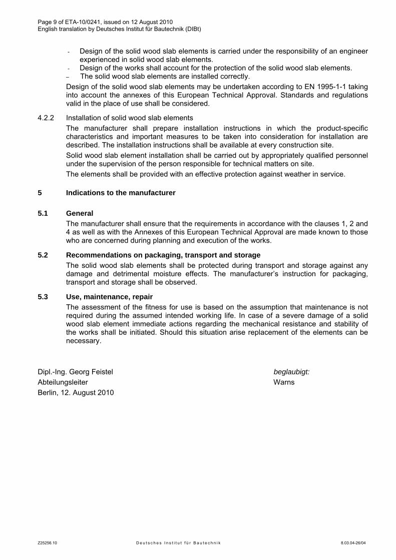
Page 9 of ETA-10/0241, issued on 12 August 2010 English translation by Deutsches Institut für Bautechnik (DIBt)
Z25256.10 D e u t s c h e s I n s t i t u t f ü r B a u t e c h n i k 8.03.04-26/04
- Design of the solid wood slab elements is carried under the responsibility of an engineer experienced in solid wood slab elements.
- Design of the works shall account for the protection of the solid wood slab elements. – The solid wood slab elements are installed correctly.
Design of the solid wood slab elements may be undertaken according to EN 1995-1-1 taking into account the annexes of this European Technical Approval. Standards and regulations valid in the place of use shall be considered.
4.2.2 Installation of solid wood slab elements The manufacturer shall prepare installation instructions in which the product-specific
characteristics and important measures to be taken into consideration for installation are described. The installation instructions shall be available at every construction site.
Solid wood slab element installation shall be carried out by appropriately qualified personnel under the supervision of the person responsible for technical matters on site.
The elements shall be provided with an effective protection against weather in service.
5 Indications to the manufacturer
5.1 General The manufacturer shall ensure that the requirements in accordance with the clauses 1, 2 and
4 as well as with the Annexes of this European Technical Approval are made known to those who are concerned during planning and execution of the works.
5.2 Recommendations on packaging, transport and storage The solid wood slab elements shall be protected during transport and storage against any
damage and detrimental moisture effects. The manufacturer’s instruction for packaging, transport and storage shall be observed.
5.3 Use, maintenance, repair The assessment of the fitness for use is based on the assumption that maintenance is not
required during the assumed intended working life. In case of a severe damage of a solid wood slab element immediate actions regarding the mechanical resistance and stability of the works shall be initiated. Should this situation arise replacement of the elements can be necessary.
Dipl.-Ing. Georg Feistel beglaubigt: Abteilungsleiter Warns Berlin, 12. August 2010
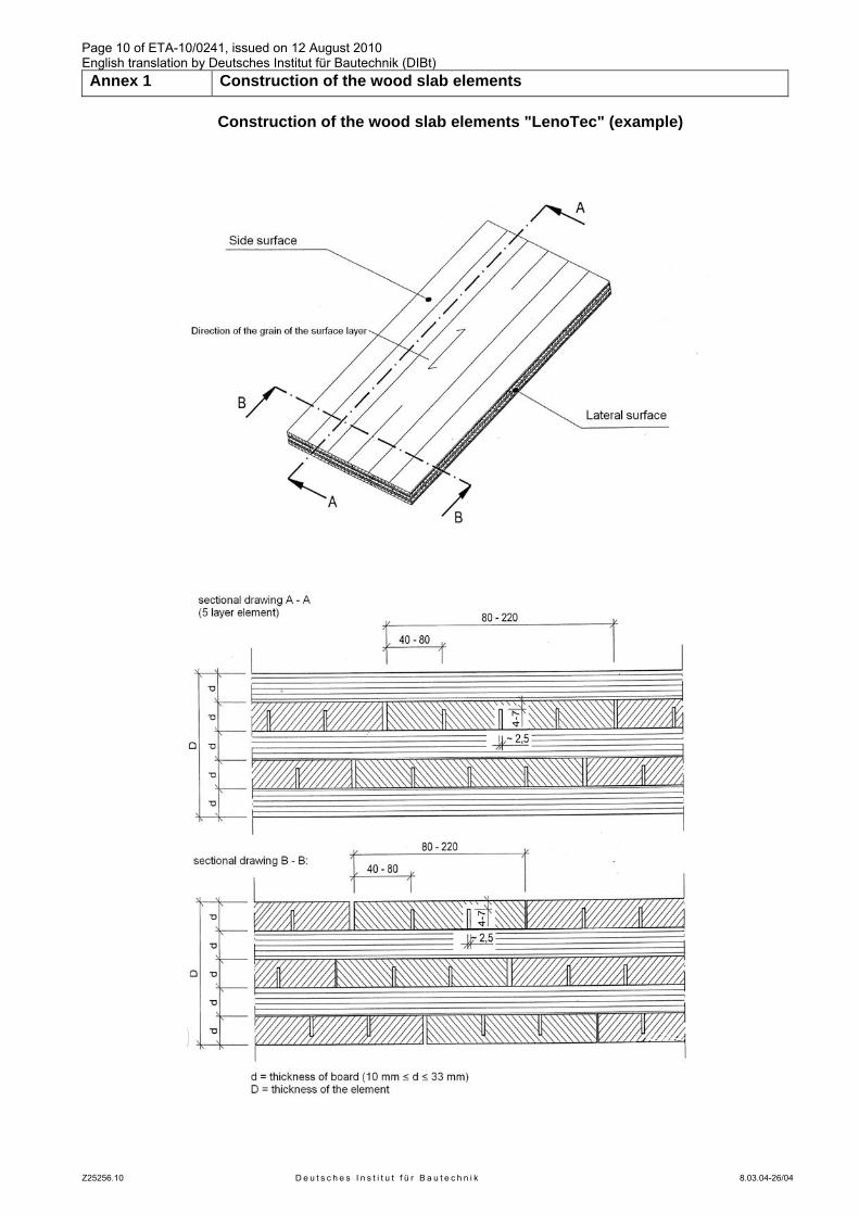
Page 10 of ETA-10/0241, issued on 12 August 2010 English translation by Deutsches Institut für Bautechnik (DIBt) Annex 1 Construction of the wood slab elements
Z25256.10 D e u t s c h e s I n s t i t u t f ü r B a u t e c h n i k 8.03.04-26/04
Construction of the wood slab elements "LenoTec" (example)
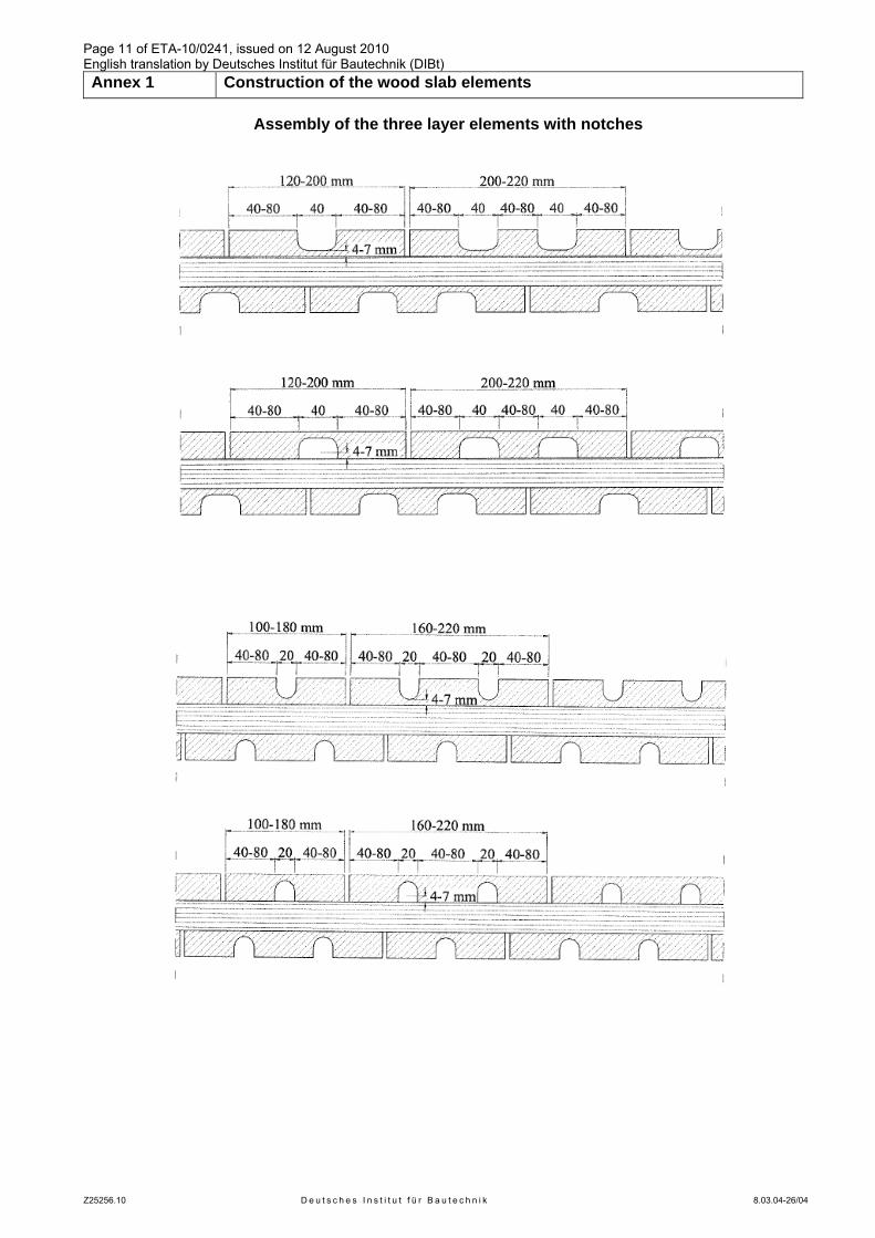
Page 11 of ETA-10/0241, issued on 12 August 2010 English translation by Deutsches Institut für Bautechnik (DIBt) Annex 1 Construction of the wood slab elements
Z25256.10 D e u t s c h e s I n s t i t u t f ü r B a u t e c h n i k 8.03.04-26/04
Assembly of the three layer elements with notches
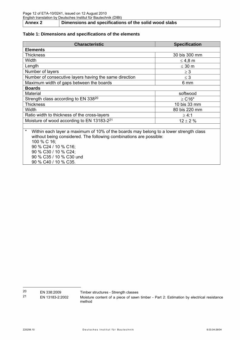
Page 12 of ETA-10/0241, issued on 12 August 2010 English translation by Deutsches Institut für Bautechnik (DIBt) Annex 2 Dimensions and specifications of the solid wood slabs
Z25256.10 D e u t s c h e s I n s t i t u t f ü r B a u t e c h n i k 8.03.04-26/04
Table 1: Dimensions and specifications of the elements
Characteristic Specification Elements Thickness 30 bis 300 mm Width ≤ 4,8 m Length ≤ 30 m Number of layers ≥ 3 Number of consecutive layers having the same direction ≤ 3 Maximum width of gaps between the boards 6 mm Boards Material softwood Strength class according to EN 33820 ≥ C16* Thickness 10 bis 33 mm Width 80 bis 220 mm Ratio width to thickness of the cross-layers ≥ 4:1 Moisture of wood according to EN 13183-221 12 ± 2 %
* Within each layer a maximum of 10% of the boards may belong to a lower strength class
without being considered. The following combinations are possible: 100 % C 16; 90 % C24 / 10 % C16; 90 % C30 / 10 % C24; 90 % C35 / 10 % C30 und 90 % C40 / 10 % C35.
20 EN 338:2009 Timber structures - Strength classes 21 EN 13183-2:2002 Moisture content of a piece of sawn timber - Part 2: Estimation by electrical resistance
method
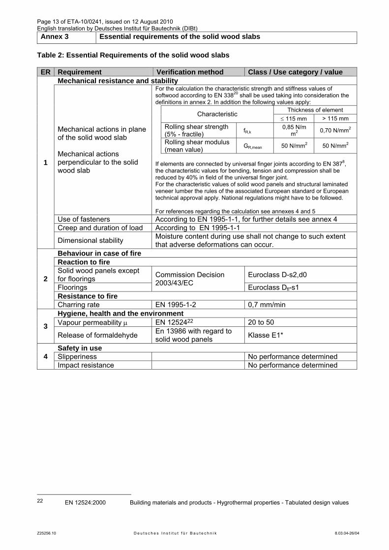
Page 13 of ETA-10/0241, issued on 12 August 2010 English translation by Deutsches Institut für Bautechnik (DIBt) Annex 3 Essential requirements of the solid wood slabs
Z25256.10 D e u t s c h e s I n s t i t u t f ü r B a u t e c h n i k 8.03.04-26/04
Table 2: Essential Requirements of the solid wood slabs ER Requirement Verification method Class / Use category / value
Mechanical resistance and stability For the calculation the characteristic strength and stiffness values of softwood according to EN 33820 shall be used taking into consideration the definitions in annex 2. In addition the following values apply: Thickness of element Characteristic
≤ 115 mm > 115 mm
Rolling shear strength (5% - fractile) fR,k
0,85 N/mm2 0,70 N/mm2
Rolling shear modulus (mean value) GR,mean 50 N/mm2 50 N/mm2
Mechanical actions in plane of the solid wood slab Mechanical actions perpendicular to the solid wood slab
If elements are connected by universal finger joints according to EN 3878, the characteristic values for bending, tension and compression shall be reduced by 40% in field of the universal finger joint. For the characteristic values of solid wood panels and structural laminated veneer lumber the rules of the associated European standard or European technical approval apply. National regulations might have to be followed. For references regarding the calculation see annexes 4 and 5
Use of fasteners According to EN 1995-1-1, for further details see annex 4 Creep and duration of load According to EN 1995-1-1
1
Dimensional stability Moisture content during use shall not change to such extent that adverse deformations can occur.
Behaviour in case of fire Reaction to fire Solid wood panels except for floorings Euroclass D-s2,d0
Floorings
Commission Decision 2003/43/EC Euroclass Dfl-s1
Resistance to fire
2
Charring rate EN 1995-1-2 0,7 mm/min Hygiene, health and the environment Vapour permeability μ EN 1252422 20 to 50 3 Release of formaldehyde En 13986 with regard to
solid wood panels Klasse E1*
Safety in use Slipperiness No performance determined 4 Impact resistance No performance determined
22 EN 12524:2000 Building materials and products - Hygrothermal properties - Tabulated design values
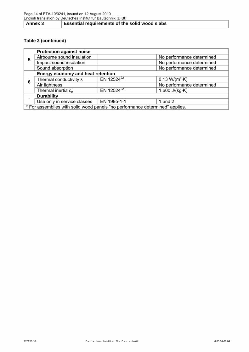
Page 14 of ETA-10/0241, issued on 12 August 2010 English translation by Deutsches Institut für Bautechnik (DIBt) Annex 3 Essential requirements of the solid wood slabs
Z25256.10 D e u t s c h e s I n s t i t u t f ü r B a u t e c h n i k 8.03.04-26/04
Table 2 (continued)
Protection against noise Airbourne sound insulation No performance determined Impact sound insulation No performance determined 5
Sound absorption No performance determined Energy economy and heat retention Thermal conductivity λ EN 1252422 0,13 W/(m²·K) Air tightness No performance determined 6
Thermal inertia cp EN 1252422 1.600 J/(kg·K) Durability - Use only in service classes EN 1995-1-1 1 und 2
* For assemblies with solid wood panels "no performance determined" applies.
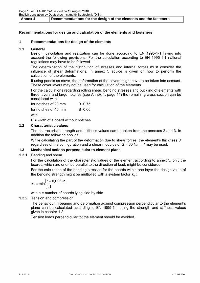
Page 15 of ETA-10/0241, issued on 12 August 2010 English translation by Deutsches Institut für Bautechnik (DIBt) Annex 4 Recommendations for the design of the elements and the fasteners
Z25256.10 D e u t s c h e s I n s t i t u t f ü r B a u t e c h n i k 8.03.04-26/04
Recommendations for design and calculation of the elements and fasteners
1 Recommendations for design of the elements
1.1 General Design, calculation and realization can be done according to EN 1995-1-1 taking into
account the following provisions. For the calculation according to EN 1995-1-1 national regulations may have to be followed.
The determination of the distribution of stresses and internal forces must consider the influence of shear deformations. In annex 5 advice is given on how to perform the calculation of the elements.
If using panels as cover, the deformation of the covers might have to be taken into account. These cover layers may not be used for calculation of the elements.
For the calculations regarding rolling shear, bending stresses and buckling of elements with three layers and large notches (see Annex 1, page 11) the remaining cross-section can be considered with:
for notches of 20 mm B·0,75 for notches of 40 mm B·0,60 with B = width of a board without notches
1.2 Characteristic values The characteristic strength and stiffness values can be taken from the annexes 2 and 3. In
addition the following applies: While calculating the part of the deformation due to shear forces, the element’s thickness D
regardless of the configuration and a shear modulus of G = 60 N/mm² may be used. 1.3 Mechanical actions perpendicular to element plane 1.3.1 Bending and shear
For the calculation of the characteristic values of the element according to annex 5, only the boards, which are oriented parallel to the direction of load, might be considered.
For the calculation of the bending stresses for the boards within one layer the design value of the bending strength might be multiplied with a system factor lk :
+ ⋅⎧
= ⎨⎩
l
1 0,025 nk min
1,1
with n = number of boards lying side by side. 1.3.2 Tension and compression
The behaviour in bearing and deformation against compression perpendicular to the element’s plane can be calculated according to EN 1995-1-1 using the strength and stiffness values given in chapter 1.2.
Tension loads perpendicular tot the element should be avoided.
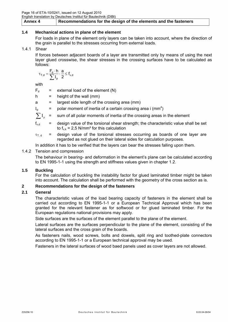
Page 16 of ETA-10/0241, issued on 12 August 2010 English translation by Deutsches Institut für Bautechnik (DIBt) Annex 4 Recommendations for the design of the elements and the fasteners
Z25256.10 D e u t s c h e s I n s t i t u t f ü r B a u t e c h n i k 8.03.04-26/04
1.4 Mechanical actions in plane of the element For loads in plane of the element only layers can be taken into account, where the direction of
the grain is parallel to the stresses occurring from external loads. 1.4.1 Shear
If forces between adjacent boards of a layer are transmitted only by means of using the next layer glued crosswise, the shear stresses in the crossing surfaces have to be calculated as follows:
dT,d v,d
p
F h a f2
⋅τ = ⋅ ≤
Ι∑
with Fd = external load of the element (N) h = height of the wall (mm) a = largest side length of the crossing area (mm) Ιp = polar moment of inertia of a certain crossing area i (mm4)
∑ pI = sum of all polar moments of inertia of the crossing areas in the element
fv,d = design value of the torsional shear strength; the characteristic value shall be set to fv,k = 2,5 N/mm² for this calculation
τT, d = design value of the torsional stresses occurring as boards of one layer are regarded as not glued on their lateral sides for calculation purposes.
In addition it has to be verified that the layers can bear the stresses falling upon them. 1.4.2 Tension and compression
The behaviour in bearing- and deformation in the element’s plane can be calculated according to EN 1995-1-1 using the strength and stiffness values given in chapter 1.2.
1.5 Buckling For the calculation of buckling the instability factor for glued laminated timber might be taken
into account. The calculation shall be performed with the geometry of the cross section as is. 2 Recommendations for the design of the fasteners 2.1 General
The characteristic values of the load bearing capacity of fasteners in the element shall be carried out according to EN 1995-1-1 or a European Technical Approval which has been granted for the relevant fastener as for softwood or for glued laminated timber. For the European regulations national provisions may apply.
Side surfaces are the surfaces of the element parallel to the plane of the element. Lateral surfaces are the surfaces perpendicular to the plane of the element, consisting of the
lateral surfaces and the cross grain of the boards. As fasteners nails, wood screws, bolts and dowels, split ring and toothed-plate connectors
according to EN 1995-1-1 or a European technical approval may be used. Fasteners in the lateral surfaces of wood baed panels used as cover layers are not allowed.
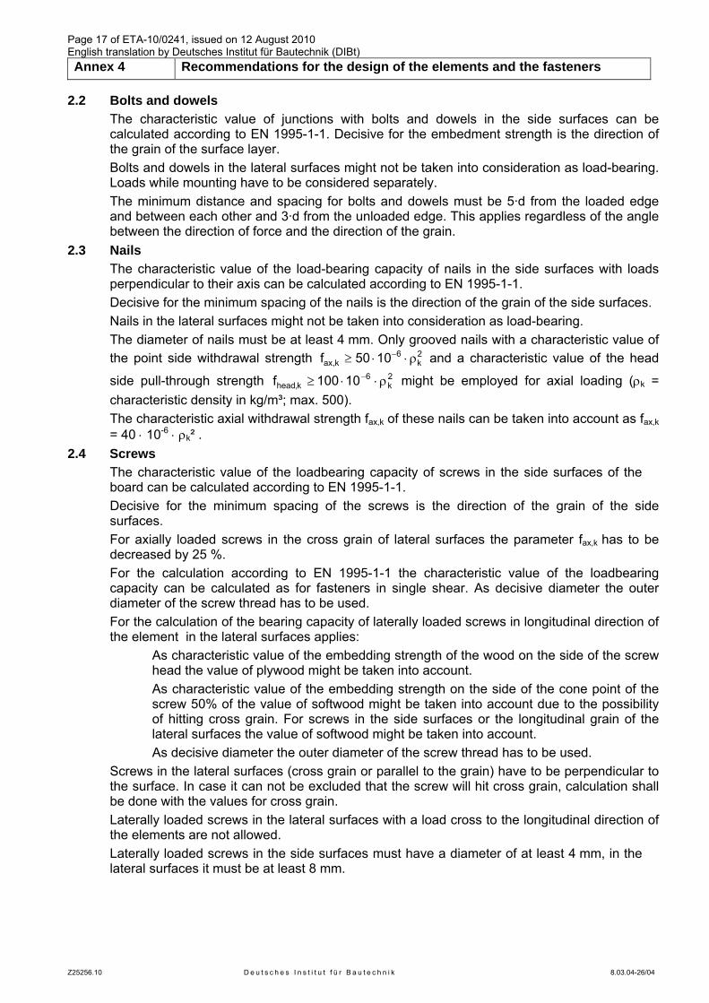
Page 17 of ETA-10/0241, issued on 12 August 2010 English translation by Deutsches Institut für Bautechnik (DIBt) Annex 4 Recommendations for the design of the elements and the fasteners
Z25256.10 D e u t s c h e s I n s t i t u t f ü r B a u t e c h n i k 8.03.04-26/04
2.2 Bolts and dowels The characteristic value of junctions with bolts and dowels in the side surfaces can be
calculated according to EN 1995-1-1. Decisive for the embedment strength is the direction of the grain of the surface layer.
Bolts and dowels in the lateral surfaces might not be taken into consideration as load-bearing. Loads while mounting have to be considered separately.
The minimum distance and spacing for bolts and dowels must be 5·d from the loaded edge and between each other and 3·d from the unloaded edge. This applies regardless of the angle between the direction of force and the direction of the grain.
2.3 Nails The characteristic value of the load-bearing capacity of nails in the side surfaces with loads perpendicular to their axis can be calculated according to EN 1995-1-1. Decisive for the minimum spacing of the nails is the direction of the grain of the side surfaces. Nails in the lateral surfaces might not be taken into consideration as load-bearing. The diameter of nails must be at least 4 mm. Only grooved nails with a characteristic value of the point side withdrawal strength 2
k6
k,ax 1050f ρ⋅⋅≥ − and a characteristic value of the head
side pull-through strength 2k
6k,head 10100f ρ⋅⋅≥ − might be employed for axial loading (ρk =
characteristic density in kg/m³; max. 500). The characteristic axial withdrawal strength fax,k of these nails can be taken into account as fax,k = 40 ⋅ 10-6 ⋅ ρk² .
2.4 Screws The characteristic value of the loadbearing capacity of screws in the side surfaces of the
board can be calculated according to EN 1995-1-1. Decisive for the minimum spacing of the screws is the direction of the grain of the side
surfaces. For axially loaded screws in the cross grain of lateral surfaces the parameter fax,k has to be
decreased by 25 %. For the calculation according to EN 1995-1-1 the characteristic value of the loadbearing
capacity can be calculated as for fasteners in single shear. As decisive diameter the outer diameter of the screw thread has to be used.
For the calculation of the bearing capacity of laterally loaded screws in longitudinal direction of the element in the lateral surfaces applies:
As characteristic value of the embedding strength of the wood on the side of the screw head the value of plywood might be taken into account.
As characteristic value of the embedding strength on the side of the cone point of the screw 50% of the value of softwood might be taken into account due to the possibility of hitting cross grain. For screws in the side surfaces or the longitudinal grain of the lateral surfaces the value of softwood might be taken into account.
As decisive diameter the outer diameter of the screw thread has to be used. Screws in the lateral surfaces (cross grain or parallel to the grain) have to be perpendicular to
the surface. In case it can not be excluded that the screw will hit cross grain, calculation shall be done with the values for cross grain.
Laterally loaded screws in the lateral surfaces with a load cross to the longitudinal direction of the elements are not allowed.
Laterally loaded screws in the side surfaces must have a diameter of at least 4 mm, in the lateral surfaces it must be at least 8 mm.
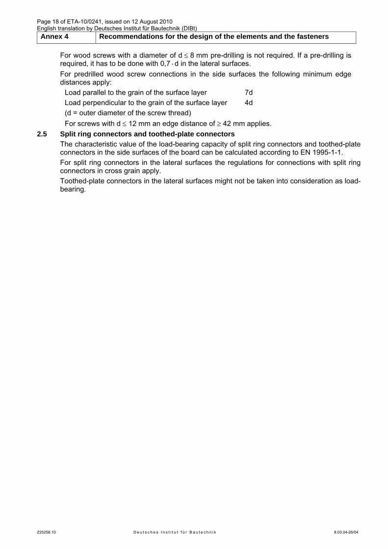
Page 18 of ETA-10/0241, issued on 12 August 2010 English translation by Deutsches Institut für Bautechnik (DIBt) Annex 4 Recommendations for the design of the elements and the fasteners
Z25256.10 D e u t s c h e s I n s t i t u t f ü r B a u t e c h n i k 8.03.04-26/04
For wood screws with a diameter of d ≤ 8 mm pre-drilling is not required. If a pre-drilling is required, it has to be done with 0,7·d in the lateral surfaces.
For predrilled wood screw connections in the side surfaces the following minimum edge distances apply:
Load parallel to the grain of the surface layer 7d Load perpendicular to the grain of the surface layer 4d (d = outer diameter of the screw thread) For screws with d ≤ 12 mm an edge distance of ≥ 42 mm applies.
2.5 Split ring connectors and toothed-plate connectors The characteristic value of the load-bearing capacity of split ring connectors and toothed-plate
connectors in the side surfaces of the board can be calculated according to EN 1995-1-1. For split ring connectors in the lateral surfaces the regulations for connections with split ring
connectors in cross grain apply. Toothed-plate connectors in the lateral surfaces might not be taken into consideration as load-
bearing.
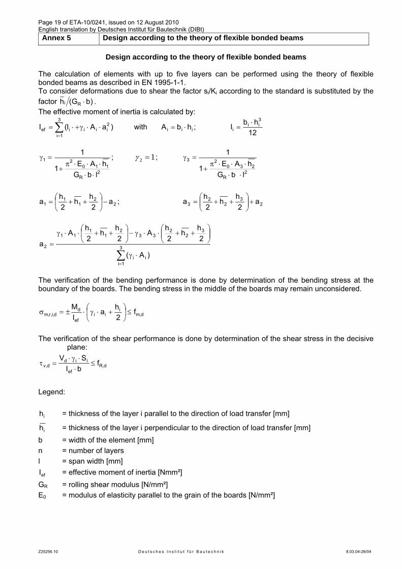
Page 19 of ETA-10/0241, issued on 12 August 2010 English translation by Deutsches Institut für Bautechnik (DIBt) Annex 5 Design according to the theory of flexible bonded beams
Z25256.10 D e u t s c h e s I n s t i t u t f ü r B a u t e c h n i k 8.03.04-26/04
Design according to the theory of flexible bonded beams The calculation of elements with up to five layers can be performed using the theory of flexible bonded beams as described in EN 1995-1-1. To consider deformations due to shear the factor si/Ki according to the standard is substituted by the factor )bG(h Ri ⋅ . The effective moment of inertia is calculated by:
∑=
⋅⋅γ+⋅=3
1i
2iiiief )aAI(I with iii hbA ⋅= ;
12hbI
3ii
i⋅
=
2R
11021
lbGhAE1
1
⋅⋅⋅⋅⋅π
+
=γ ; 12 =γ ;
2R
23023
lbGhAE1
1
⋅⋅⋅⋅⋅π
+
=γ
22
11
1 a2
hh
2h
a −⎟⎠
⎞⎜⎝
⎛++= ; 2
32
23 a
2h
h2
ha +⎟⎟
⎠
⎞⎜⎜⎝
⎛++=
∑=
⋅γ
⎟⎟⎠
⎞⎜⎜⎝
⎛++⋅⋅γ−⎟
⎠
⎞⎜⎝
⎛++⋅⋅γ
= 3
1iii
32
233
21
111
2
)A(
2h
h2
hA
2h
h2h
Aa
The verification of the bending performance is done by determination of the bending stress at the boundary of the boards. The bending stress in the middle of the boards may remain unconsidered.
d,mi
iief
dd,i,r,m f
2ha
IM
≤⎟⎠
⎞⎜⎝
⎛ +⋅γ⋅±=σ
The verification of the shear performance is done by determination of the shear stress in the decisive
plane:
d,Ref
iidd,v f
bISV
≤⋅⋅γ⋅
=τ
Legend:
ih = thickness of the layer i parallel to the direction of load transfer [mm]
ih = thickness of the layer i perpendicular to the direction of load transfer [mm] b = width of the element [mm] n = number of layers l = span width [mm]
efI = effective moment of inertia [Nmm²] GR = rolling shear modulus [N/mm²] E0 = modulus of elasticity parallel to the grain of the boards [N/mm²]