Adaptable Imaging Package for Remote Vehicles · Laboratoire de technologie écologique (ECOL),...
28
1 Adaptable Imaging Package for Remote Vehicles Jean-Luc Liardon † , D. A. Barry Laboratoire de technologie écologique (ECOL), Institut d’ingénierie de l’environnement (IIE), Faculté de l’environnement naturel, architectural et construit (ENAC), Station 2, Ecole Polytechnique Fédérale de Lausanne (EPFL), 1015 Lausanne, Switzerland. Emails: jean- [email protected], [email protected]. Telephone: +41 (21) 693-8073, +41 (21) 693-5576. Facsimile: +41 (21) 693-8035 Accepted for publication by HardwareX, 18 April 2017. Doi: 10.1016/j.ohx.2017.04.001 † To whom correspondence should be addressed
-
Upload
duongkhuong -
Category
Documents
-
view
222 -
download
0
Transcript of Adaptable Imaging Package for Remote Vehicles · Laboratoire de technologie écologique (ECOL),...
1
Adaptable Imaging Package for Remote Vehicles
Jean-Luc Liardon†, D. A. Barry
Laboratoire de technologie écologique (ECOL), Institut d’ingénierie de l’environnement (IIE),
Faculté de l’environnement naturel, architectural et construit (ENAC), Station 2, Ecole
Polytechnique Fédérale de Lausanne (EPFL), 1015 Lausanne, Switzerland. Emails: jean-
[email protected], [email protected]. Telephone: +41 (21) 693-8073, +41 (21) 693-5576.
Facsimile: +41 (21) 693-8035
Accepted for publication by HardwareX, 18 April 2017. Doi: 10.1016/j.ohx.2017.04.001
† To whom correspondence should be addressed
2
Abstract: An easy-to-customize, low-cost solution for remote imagery is described. The system,
denoted ImPROV (Imaging Package for Remote Vehicles), supports multiple cameras, live
streaming, long-range encrypted communication using mobile networks, positioning and time-
stamped imagery, etc. The adaptability of the system is demonstrated by its deployment on
different remotely operated or autonomous vehicles, which include model aircraft, drones,
balloon, kite and a submarine.
Keywords: 4G; Aerial imagery; Balloon; Camera; Drone; EasyCAP; Encryption; FLIR; GPL; GPS;
Kite; ImPROV; Infrared; Live-streaming; LTE; LWIR; Mobile Network; Positioning; RGB; ROV;
Submarine; Time-stamping; UAV; VPN
Acronyms: APN Access Point Name, ESC Electronic Speed Controller, FPV First Person View,
GPL GNU General Public License, GPS Global Positioning System, LiPo Lithium-Polymer,
ImPROV Image Package for Remote Vehicles, LTE Long-Term Evolution, LWIR Long Wave
Infrared, RGB Red Green Blue, ROV Remotely Operated Vehicle, SSH Secure Socket Shell, UART
Universal Asynchronous Receiver/Transmitter, UAV Unmanned Aerial Vehicle, VPN Virtual
Private Network
3
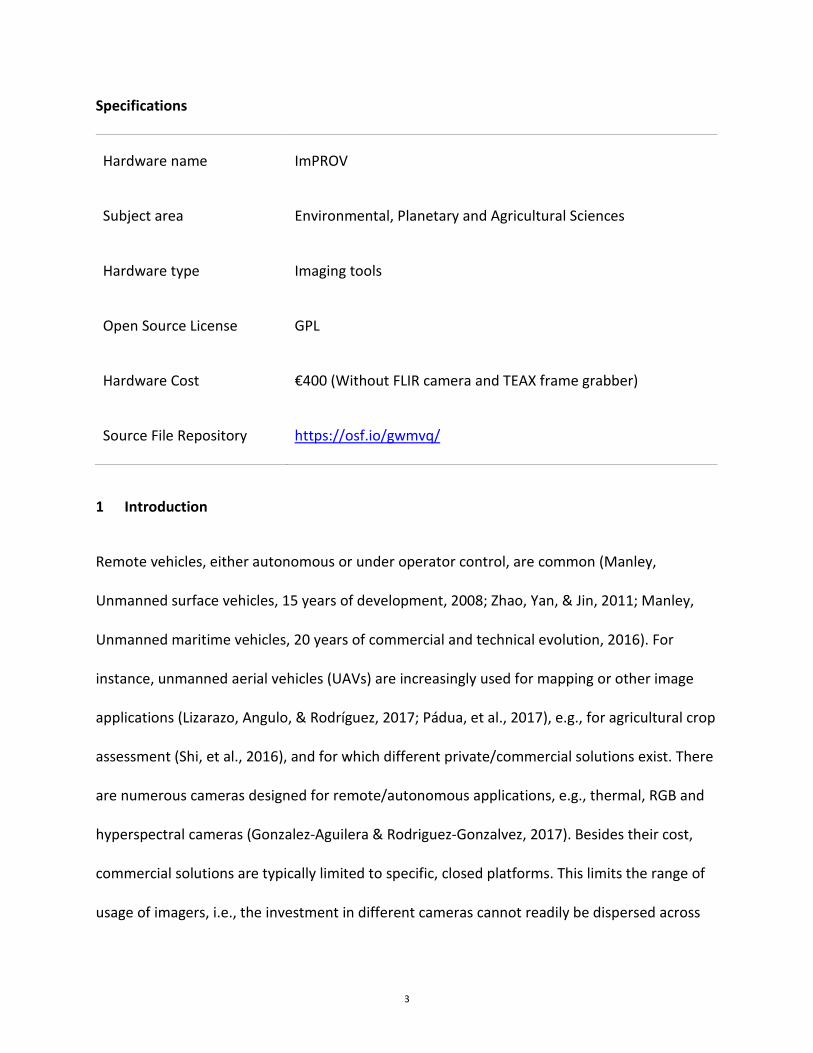
Specifications
Hardware name ImPROV
Subject area Environmental, Planetary and Agricultural Sciences
Hardware type Imaging tools
Open Source License GPL
Hardware Cost €400 (Without FLIR camera and TEAX frame grabber)
Source File Repository https://osf.io/gwmvq/
1 Introduction
Remote vehicles, either autonomous or under operator control, are common (Manley,
Unmanned surface vehicles, 15 years of development, 2008; Zhao, Yan, & Jin, 2011; Manley,
Unmanned maritime vehicles, 20 years of commercial and technical evolution, 2016). For
instance, unmanned aerial vehicles (UAVs) are increasingly used for mapping or other image
applications (Lizarazo, Angulo, & Rodríguez, 2017; Pádua, et al., 2017), e.g., for agricultural crop
assessment (Shi, et al., 2016), and for which different private/commercial solutions exist. There
are numerous cameras designed for remote/autonomous applications, e.g., thermal, RGB and
hyperspectral cameras (Gonzalez-Aguilera & Rodriguez-Gonzalvez, 2017). Besides their cost,
commercial solutions are typically limited to specific, closed platforms. This limits the range of
usage of imagers, i.e., the investment in different cameras cannot readily be dispersed across
4
different vehicles. Even if an imaging package is open to modifications, there remains the major
logistical challenge of integration of the system to different vehicles.
The cost of hardware is no longer a barrier to system development (Colomina & Molina, 2014).
Indeed, if a mobile imaging system is divided into its imaging and non-imaging components, the
cost of the latter is remarkably low. The cost of the imagers, of course, is dependent on the
quality demanded by the envisaged application. Here, too, however, the cost/quality ratio is
increasingly attractive.
In this contribution, we present ImPROV (Image Package for Remote Vehicles), an adaptable
imaging system suitable for deployment on autonomous/remote vehicles. As in similar
developments (Bin & Amahah, 2009), the system leverages the readily available hardware used
in autonomous vehicle control and associated open source ground station and mission planning
software. ImPROV is fully customizable for different imaging platforms. At the same time, it
offers a range of attractive features, including full remote control, positioning, time-stamping,
real-time streaming, encrypted communications, etc.
5
2 Material
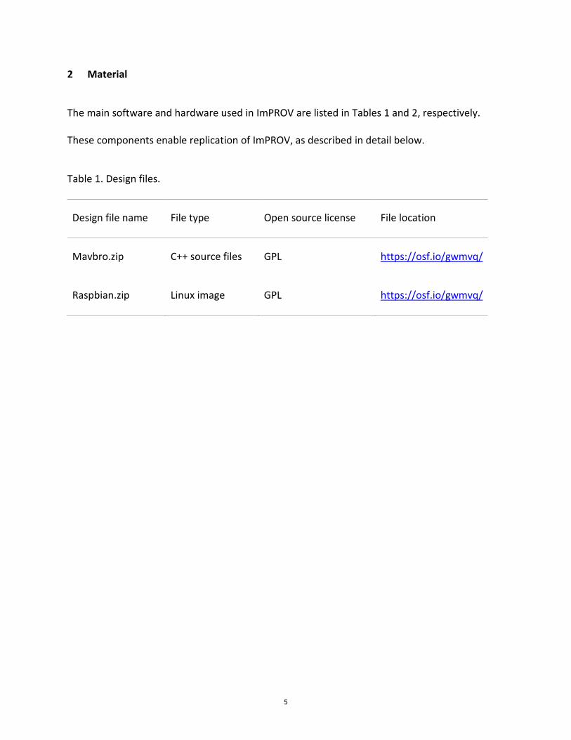
The main software and hardware used in ImPROV are listed in Tables 1 and 2, respectively.
These components enable replication of ImPROV, as described in detail below.
Table 1. Design files.
Design file name File type Open source license File location
Mavbro.zip C++ source files GPL https://osf.io/gwmvq/
Raspbian.zip Linux image GPL https://osf.io/gwmvq/
6
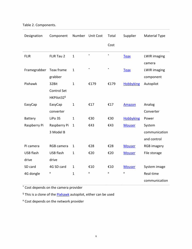
Table 2. Components.
Designation Component Number Unit Cost Total
Cost
Supplier Material Type
FLIR FLIR Tau 2 1 * * Teax LWIR imaging
camera
Framegrabber Teax frame
grabber
1 * * Teax LWIR imaging
component
Pixhawk 32Bit
Control Set
HKPilot32§
1 €179 €179 Hobbyking Autopilot
EasyCap EasyCap
converter
1 €17 €17 Amazon Analog
Converter
Battery LiPo 3S 1 €30 €30 Hobbyking Power
Raspberry Pi Raspberry Pi
3 Model B
1 €43 €43 Mouser System
communication
and control
Pi camera RGB camera 1 €28 €28 Mouser RGB imagery
USB flash
drive
USB flash
drive
1 €20 €20 Mouser File storage
SD card 4G SD card 1 €10 €10 Mouser System image
4G dongle ¤ 1 ¤ ¤ ¤ Real-time
communication * Cost depends on the camera provider § This is a clone of the Pixhawk autopilot, either can be used ¤ Cost depends on the network provider
7
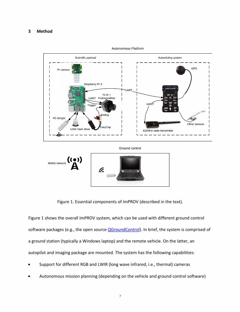
3 Method
Figure 1. Essential components of ImPROV (described in the text).
Figure 1 shows the overall ImPROV system, which can be used with different ground control
software packages (e.g., the open source QGroundControl). In brief, the system is comprised of
a ground station (typically a Windows laptop) and the remote vehicle. On the latter, an
autopilot and imaging package are mounted. The system has the following capabilities:
• Support for different RGB and LWIR (long wave infrared, i.e., thermal) cameras
• Autonomous mission planning (depending on the vehicle and ground control software)
8
• Support for multiple, simultaneously deployed vehicles
• As part of the ground control software, recording of autopilot sensor data (air pressure,
vehicle motion characteristics including acceleration and orientation, etc.)
• Location and time stamping of all images
• Synchronized images
• Live streaming of all cameras
• Live tracking of remote vehicles at the ground station
• Radio communication
• Communication over 4G (LTE) mobile networks (with encrypted communication over a
VPN), which removes any distance restrictions between the ground station and remote
vehicle(s)
• Ability to include other sensors using the Pixhawk MAVLink communication protocol
We interfaced the following cameras, although many other choices exist:
• FLIR Tau 2 (LWIR)
• FLIR Lepton (LWIR)
• Raspberry Pi camera (1 and 2, RGB)
• Logitech C920 (RGB)
• Generic webcams (RGB)
As indicated, the implementation of the (C++) software permits straightforward integration of
new cameras or other sensors. For instance, as a safety feature for our autonomous aerial
9
vehicles, we include a parachute for landing on water. The parachute launch is preceded by an
automatic system shutdown to prevent possible water damage.
The ImPROV system is versatile as it is:
• Easy to customize
• Uses inexpensive, off-the-shelf components
• Compatible with any camera subject to integration into the system
3.1 Build Instructions
3.1.1 Hardware assembly
The system components are depicted in Figure 1, and are connected as described below. The
final hardware configuration is adapted to the target remote vehicle.
3.1.1.1 Scientific payload
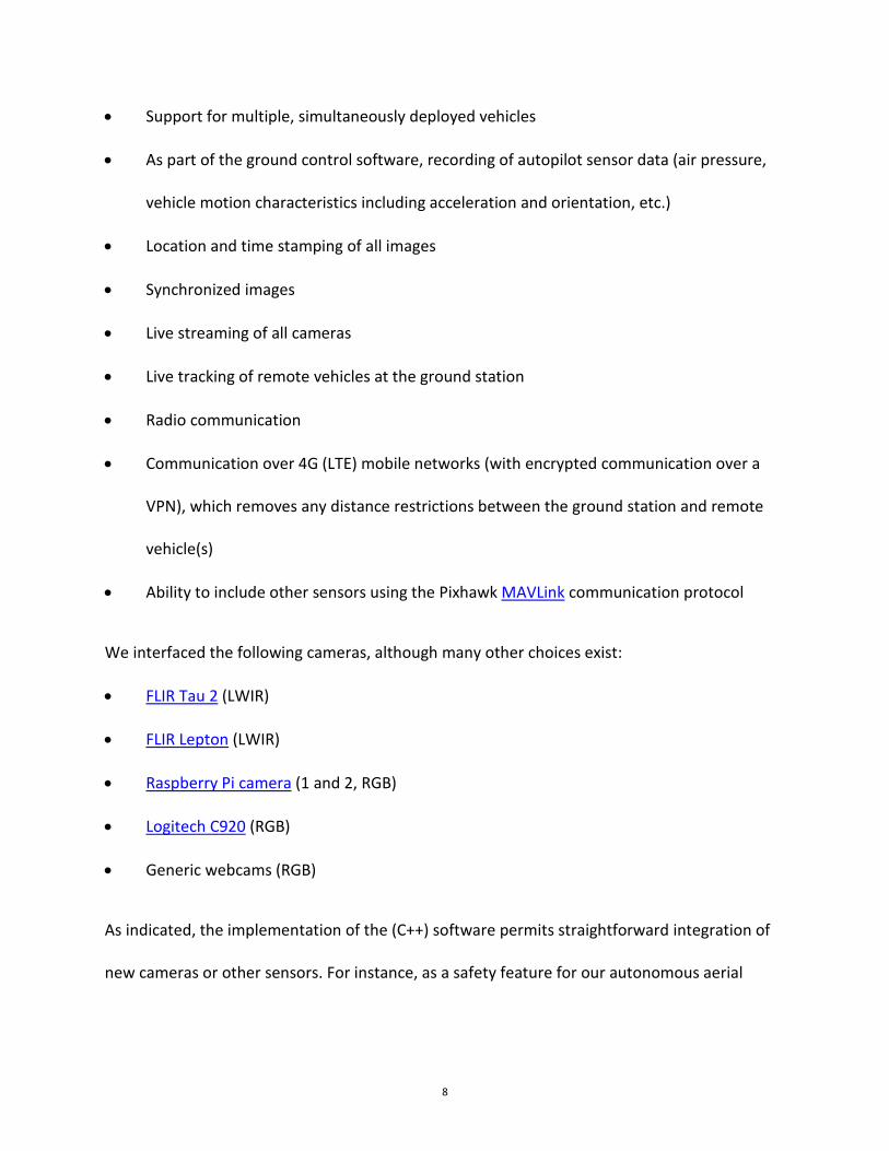
1) Thermal Imagery. We use a FLIR camera and Teax framegrabber, which together create a
compact thermal imaging solution. The FLIR camera and the framegrabber are assembled
following instructions from Teax, who provide a step-by-step guide. Figure 2 shows the
assembled camera.
10
Figure 2. FLIR Tau 2 (front) with Teax framegrabber (mounted at the camera’s rear).
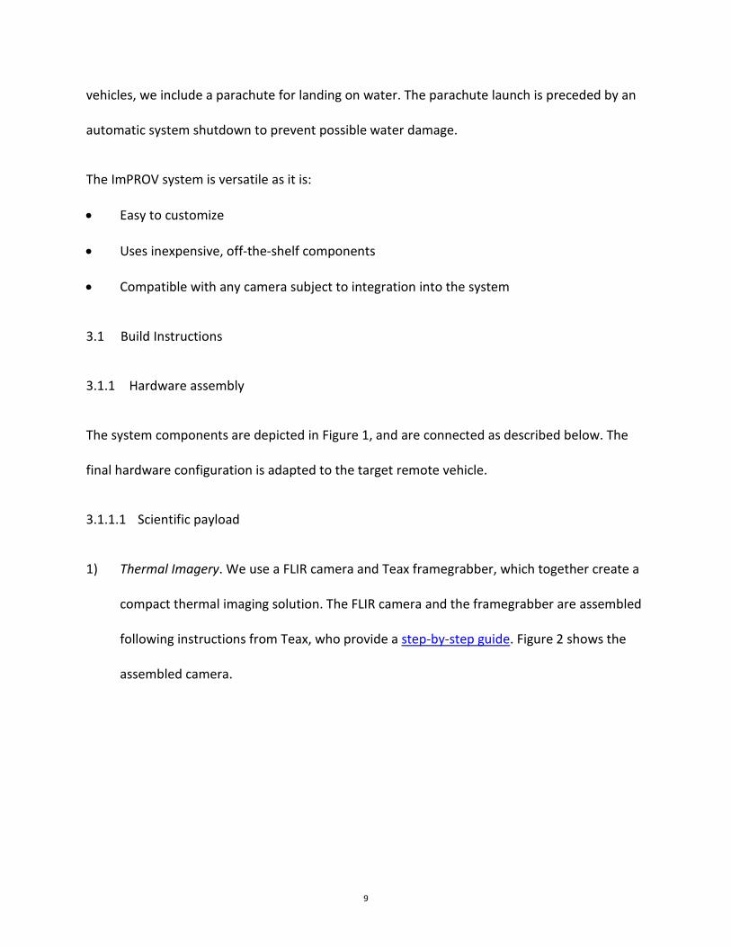
2) RGB Imagery. The Raspberry Pi camera is a cost-effective RGB imaging solution. For setup,
simply connect the Raspberry Pi computer to the Pi camera using the CSI2 camera port, as
shown in Figure 3.
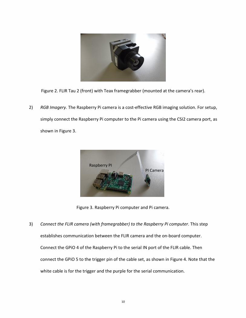
3) Connect the FLIR camera (with framegrabber) to the Raspberry Pi computer. This step
establishes communication between the FLIR camera and the on-board computer.
Connect the GPiO 4 of the Raspberry Pi to the serial IN port of the FLIR cable. Then
connect the GPiO 5 to the trigger pin of the cable set, as shown in Figure 4. Note that the
white cable is for the trigger and the purple for the serial communication.
Figure 3. Raspberry Pi computer and Pi camera.
PI Camera Raspberry PI
11
Figure 4. Connection between FLIR Tau 2 camera and the Raspberry Pi computer.
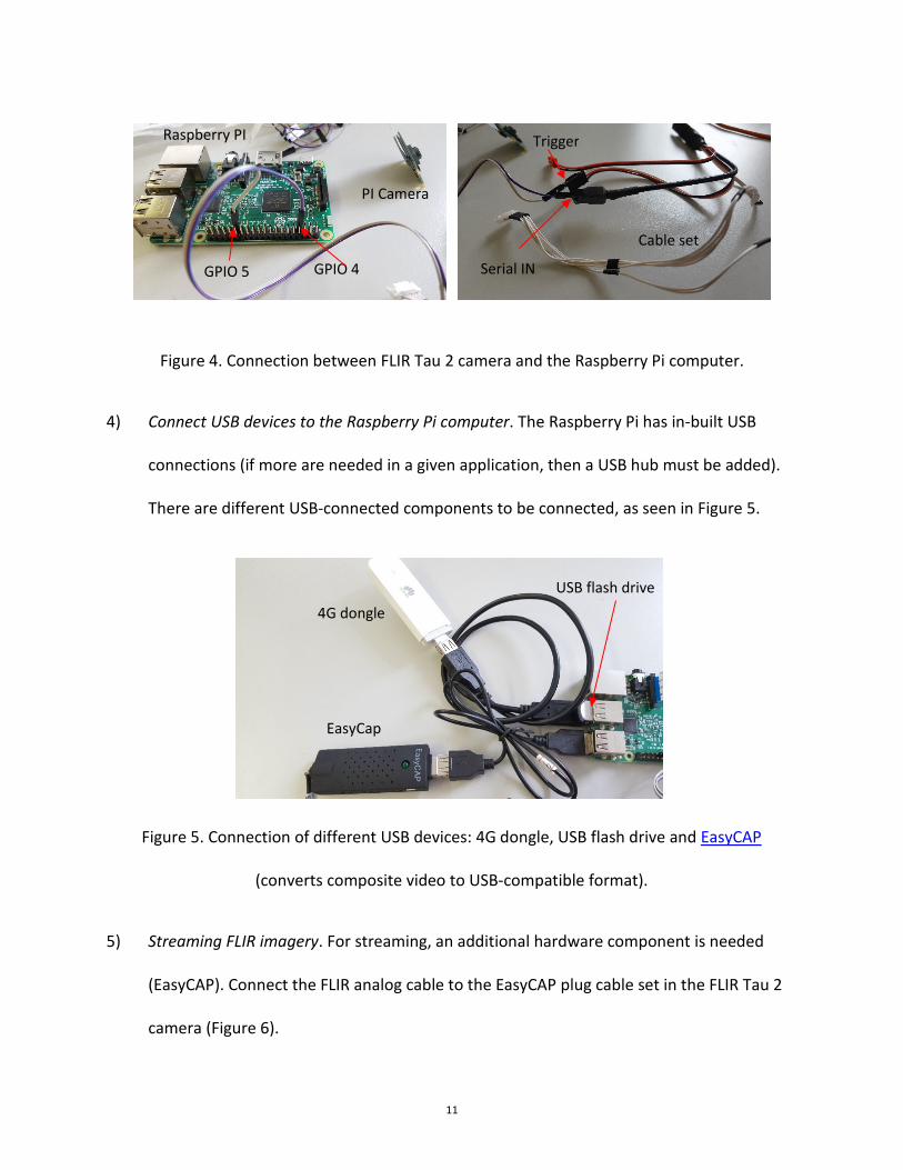
4) Connect USB devices to the Raspberry Pi computer. The Raspberry Pi has in-built USB
connections (if more are needed in a given application, then a USB hub must be added).
There are different USB-connected components to be connected, as seen in Figure 5.
Figure 5. Connection of different USB devices: 4G dongle, USB flash drive and EasyCAP
(converts composite video to USB-compatible format).
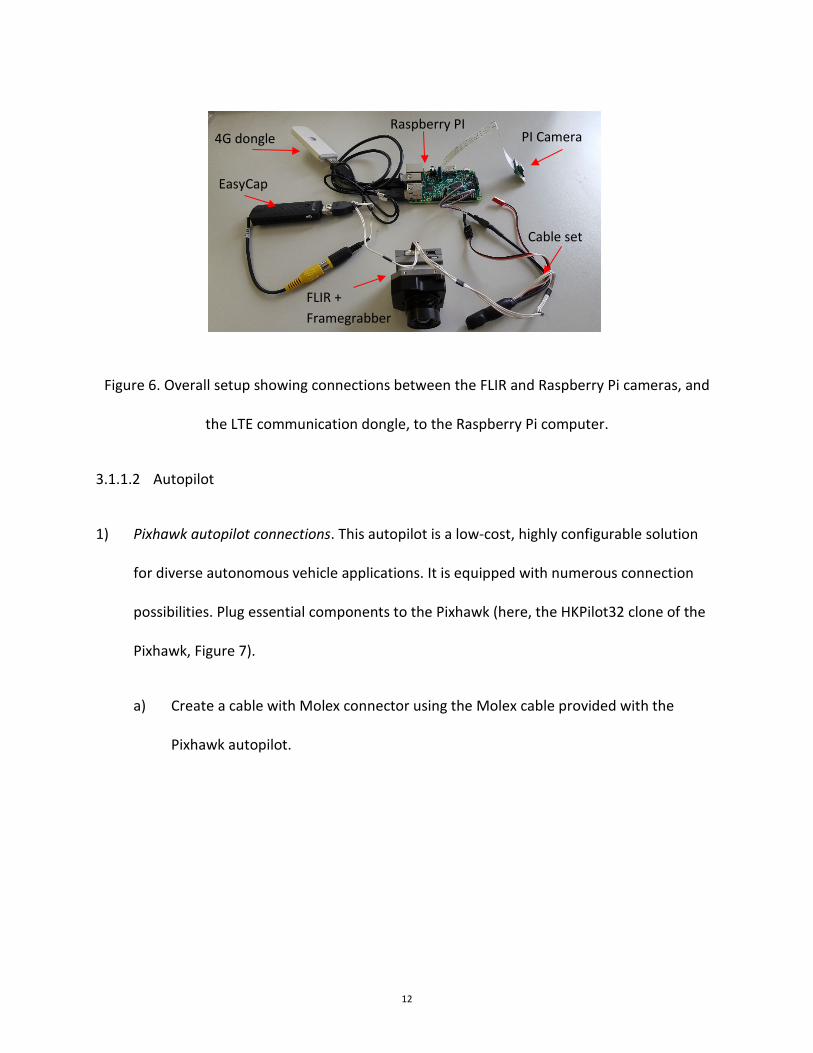
5) Streaming FLIR imagery. For streaming, an additional hardware component is needed
(EasyCAP). Connect the FLIR analog cable to the EasyCAP plug cable set in the FLIR Tau 2
camera (Figure 6).
PI Camera
Raspberry PI
GPIO 4 GPIO 5 Serial IN
Trigger
Cable set
4G dongle
EasyCap
USB flash drive
12
Figure 6. Overall setup showing connections between the FLIR and Raspberry Pi cameras, and
the LTE communication dongle, to the Raspberry Pi computer.
3.1.1.2 Autopilot
1) Pixhawk autopilot connections. This autopilot is a low-cost, highly configurable solution
for diverse autonomous vehicle applications. It is equipped with numerous connection
possibilities. Plug essential components to the Pixhawk (here, the HKPilot32 clone of the
Pixhawk, Figure 7).
a) Create a cable with Molex connector using the Molex cable provided with the
Pixhawk autopilot.
4G dongle
EasyCap
FLIR + Framegrabber
Raspberry PI PI Camera
Cable set
13
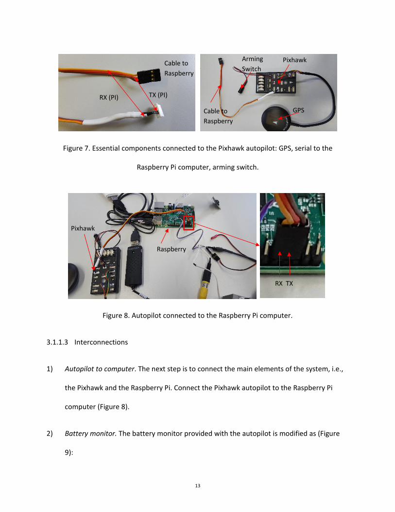
Figure 7. Essential components connected to the Pixhawk autopilot: GPS, serial to the
Raspberry Pi computer, arming switch.
3.1.1.3 Interconnections
1) Autopilot to computer. The next step is to connect the main elements of the system, i.e.,
the Pixhawk and the Raspberry Pi. Connect the Pixhawk autopilot to the Raspberry Pi
computer (Figure 8).
2) Battery monitor. The battery monitor provided with the autopilot is modified as (Figure
9):
Figure 8. Autopilot connected to the Raspberry Pi computer.
Pixhawk
GPS
Arming Switch
Cable to Raspberry
Cable to Raspberry
TX (PI) RX (PI)
Pixhawk
Raspberry
RX TX
14
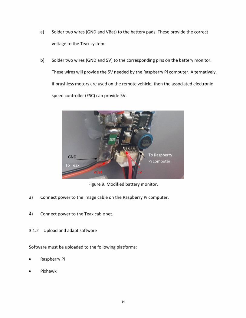
a) Solder two wires (GND and VBat) to the battery pads. These provide the correct
voltage to the Teax system.
b) Solder two wires (GND and 5V) to the corresponding pins on the battery monitor.
These wires will provide the 5V needed by the Raspberry Pi computer. Alternatively,
if brushless motors are used on the remote vehicle, then the associated electronic
speed controller (ESC) can provide 5V.
Figure 9. Modified battery monitor.
3) Connect power to the image cable on the Raspberry Pi computer.
4) Connect power to the Teax cable set.
3.1.2 Upload and adapt software
Software must be uploaded to the following platforms:
• Raspberry Pi
• Pixhawk
5V
To Raspberry Pi computer
VBat
GND
To Teax
15
3.1.2.1 Raspberry Pi
The Raspberry operation system – specifically Raspbian lite – is saved on a microSD card.
Raspbian lite was modified as follows:
• Read-Only. Allows powering down without corrupting the SD card contents.
• Automatic 4G connection. If a 4G/LTE dongle is available, the computer will establish an
internet connection.
• Symlinks. Handle specific devices such as EasyCap.
• OpenVPN. Configure the computer to automatically connect to the VPN server.
• ImPROV application software. Handles camera links and communication with the
autopilot and the user computer.
The modified Raspbian image is available from OSF. It is installed on the MicroSD card following
the Raspberry official documentation.
The (optional) 4G communication requires:
• An OpenVPN server
• 4G connection parameters such as APN, which accompany the 4G subscription
To connect for the first time to the Raspberry Pi computer, simply use an Ethernet cable
between the Pi and the accessing computer (used for setup). Once powered on, the Raspberry
Pi is accessible using SSH with the following credentials:
16
• IP address: raspberrypi.mshome.net
• Login: pi
• Password (case sensitive): raspberry
3.1.2.1.1 OpenVPN Setup
Encrypted internet communication over 4G/LTE is provided by the OpenVPN connection, which
entails configuration of three computers:
• Ground station computer
• Server
• Raspberry Pi
The setup is straightforward (Liardon & Barry, 2017), with steps detailed in the document
ImPROV_VPN.pdf (available from OSF).
3.1.2.1.2 4G Communication
The following steps configure the network-manager on the Raspberry Pi computer. From a shell
command:
1) Type sudo nmcli con edit, then enter. You are now in a connection utility.
2) Type gsm and then press enter.
3) Type set gsm.apn APN_ADDRESS and press enter. The APN_ADRESS is provided by the
with the LTE subscription (gprs.swisscom.ch for Swisscom).
17
4) Type save, then yes.
5) Type quit.
After a reboot, the Raspberry Pi computer will automatically connect to the 4G/3G network.
3.1.2.1.3 ImPROV Software customization
The name of the custom software used in the Raspberry Pi is Mavbro. The default configuration
of the provided software is:
• FLIR Tau 2 with framegrabber
• Raspberry Pi Camera
• Communication through 4G (OpenVPN, to IP 10.8.0.5)
It can be customized by modifying and recompiling the C++ source code (mavbro.zip), using the
tool Eclipse IDE. Full details are provided in mavbro_dev.docx on OSF.
3.1.2.2 Pixhawk autopilot
Either of the following software stacks that can be used with the autopilot:
• PX4 Stack
• Ardupilot
We used Arduplane 3.5.3 (from Ardupilot). Other versions are suitable so long as they use
MAVLink1 as communication protocol. Recent versions of the Arduplane software set this by
specifying the SERIAL1_PROTOCOL parameter.
18
3.1.2.3 Ground Station
Any MAVLink-compliant ground control software can be used, e.g.,
• Mission Planner
• APM Planner 2
• QGroundControl
If the live streaming is needed, then the preferred software should be modified by adding
additional commands, and gstreamer should be installed. All the above are open source, and
modifiable. We selected QGroundcontrol and adapted it to control the different cameras by
adding buttons that, once clicked, send the following MAVLink command:
• Command: MAV_CMD_DO_CONTROL_VIDEO
• Param1: Camera ID
• Param2: Camera Mode (0: Imaging, 1: Streaming, 2:Recording, 3:Recording and
streaming, 4: Streaming through mavlink,5:OFF
The above listed ground control programs also offer the possibility to create custom commands
online, without modifying the source code (described in the selected software related
documentation). This solution is convenient and straoghtforward. We modified the software for
interface tweaking.
The open-source software gstreamer is installed to the ground station to enable live streaming
of the different cameras. Both normal and developer 32-bit versions are needed, which are
19
available at the gstreamer download page. For example, for windows, install gstreamer-1.0-
x86-1.8.1.msi and gstreamer-1.0-devel-x86-1.8.1.msi.
Conveniently, QGrouncontrol has gstreamer embedded. To watch the stream with other
ground station programs, first launch a gstreamer command line. On Windows, it would be:
• gst-launch-1.0 udpsrc port=5600 ! application/x-rtp,payload=96 ! rtph264depay ! queue !
avdec_h264 ! autovideosink sync=false. Note: port=5600 refers to the RGB stream and
port=5601 to the FLIR stream.
3.2 Operation Instructions
Although the operation depends on the chosen platform, the following sequence is always
followed:
1) Connect the battery
2) Switch on computer; connect to 4G; connect to OpenVPN
3) Setup the mission using the ground-control software
4) Arm the autopilot on the remote vehicle using the hardware switch
5) Check the autopilot behavior in manual and semi-auto modes
6) Arm the remote vehicle from the ground control
7) Launch the (soon-to-be) remote vehicle
8) During the mission, monitor the imagery using streaming over 4G/LTE
9) At mission completion, disarm the remote vehicle
20
Where 4G is not available, it is still possible to operate the remote vehicle using the basic radio
communication that can be connected directly to the Pixhawk autopilot. The system then works
as described above except for live streaming.
4 Performance
The overall performance of the package depends on the quality of the integrated cameras,
autopilot (hardware and firmware), GPS, mobile network, etc., as well as the application. For
the individual parts of the system, however, some remarks on performance can be made:
Timestamp: Each packet from the autopilot is sent to the Raspberry Pi with a micro-second
accuracy timestamp. The frequency of each packet can be defined in the autopilot parameters.
The highest autopilot frequency 10 is Hz, so the largest time difference between the picture
and the sensor packet is around 100 ms. Note that a higher precision could be achieved by
modifying the autopilot firmware and ImPROV code with the goal of implementing a custom
camera trigger message that would contain the needed information for more precise
timestamping. This step in not necessary for our applications.
Position: The position accuracy and precision is defined by the used GPS. With an Ublox Neo-
m8N GPS (as used in the current setup), one can have a 2.5 m horizontal accuracy. This could be
replaced with an RTK GPS that has cm-level level accuracy. Note that, if the GPS fails, then the
autopilot software (Ardupilot) can navigate using dead reckoning.
Altitude: The altitude is computed using both the GPS and barometer data in the Pixhawk.
Therefore, the precision depends on the firmware used (PX4 or APM). In the case of APM, used

21
in our system, an accuracy of around 2 m can be achieved. As mentioned above, higher
accuracy could be achieved with an RTK GPS.
Attitude: The MEMs accelerometer and gyrometer sensors of the autopilot are used to
estimate the attitude of the system. The in-built data fusion carried out by the autopilot allows
an accuracy of 1-2 ° for both static and dynamic behavior. For better results, a high accuracy
IMU could be used with the Raspberry Pi.
Streaming: The 4G system has a maximum bandwidth of 150 Mbit/s, however this maximum is
often throttled by telecom operators. Our field testing achieved bandwidths of 6-10 Mbit/s,
which permitted simultaneous streaming of HD imagery from 2-3 cameras, as well as a latency
of up to 500 ms between the remote vehicle and the ground station.
5 Example Applications
We have tested the system on different platforms, with different cameras. We present two
examples:
• Kite Aerial Imagery
• Long range unmanned aerial vehicle
5.1 Kite Aerial Imagery
Steady wind conditions facilitate kite imagery, which is low-cost, easily deployable and usually
not subject to legal restrictions. Figure 10 shows the kite we used and the adapted ImPROV
package. One can recognize the different essential components described previously.
22
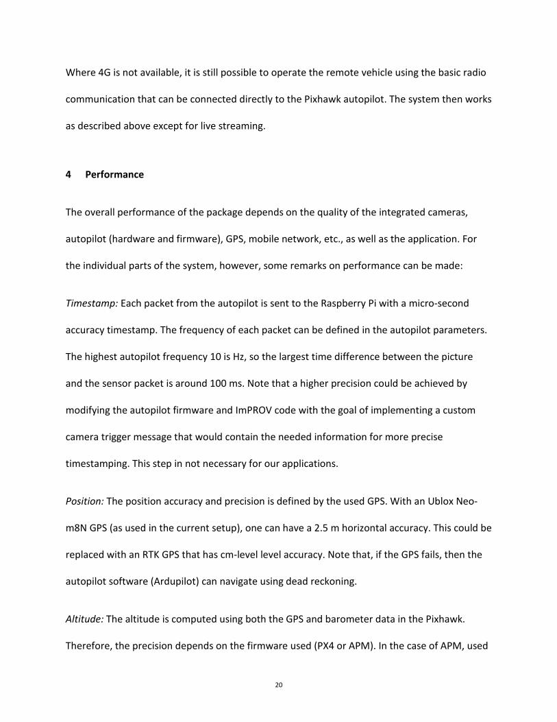
Figure 10. Kite (left) and the ImPROV imagery package (right) used with it.
23
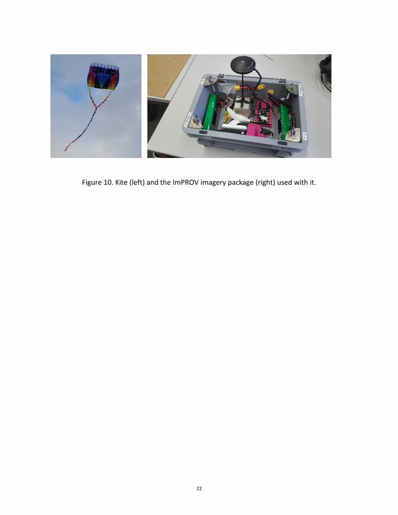
Figure 11. Sample images from a kite imagery mission in a reclaimed land area (Jiangsu,
China). In each row, thermal images are on the left, and RGB on the right. For the latter, note
that the RGB Pi camera was operated with the NIR filter removed. Top two rows – bare soil,
bottom row – small bushes and rocks.
24
As shown in Figure 10, we used 3D printing to fix all the components inside a small box. During
operation, the box is attached to the kite tether line using a Picavet rig. The setup in Figure 10
was successfully used to survey a reclaimed coastal site in Jiangsu, China. The length of the kite
tether was 100 m, and the above ground height of the ImPROV package (Figure 10, right) was
around 40 m. Figure 11 show sample images from this mission, which qualitatively demonstrate
the different information content derived from thermal and RGB cameras.
5.2 UAV
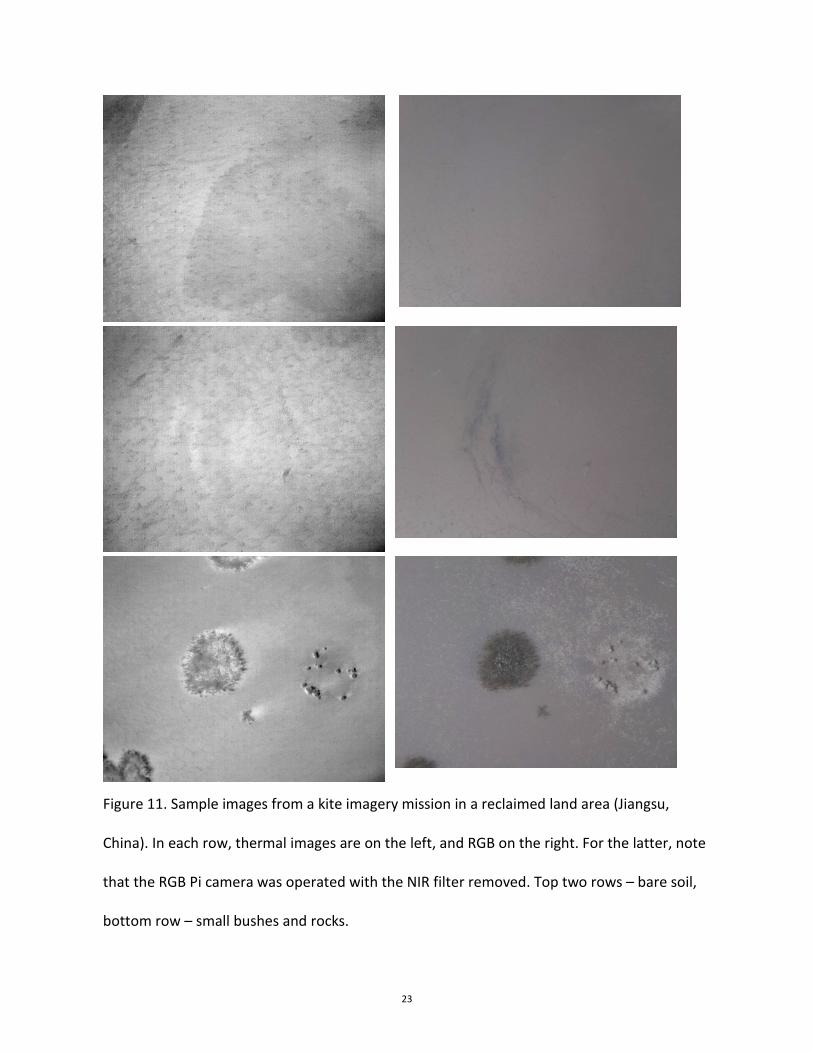
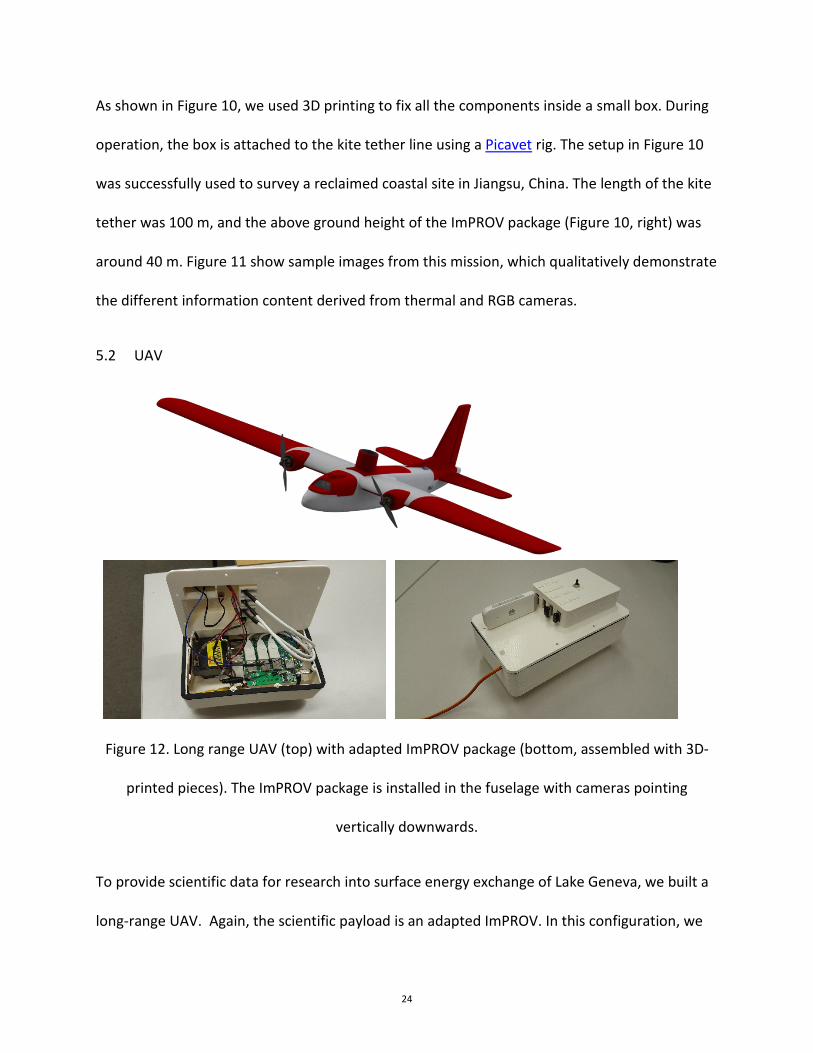
Figure 12. Long range UAV (top) with adapted ImPROV package (bottom, assembled with 3D-
printed pieces). The ImPROV package is installed in the fuselage with cameras pointing
vertically downwards.
To provide scientific data for research into surface energy exchange of Lake Geneva, we built a
long-range UAV. Again, the scientific payload is an adapted ImPROV. In this configuration, we
25
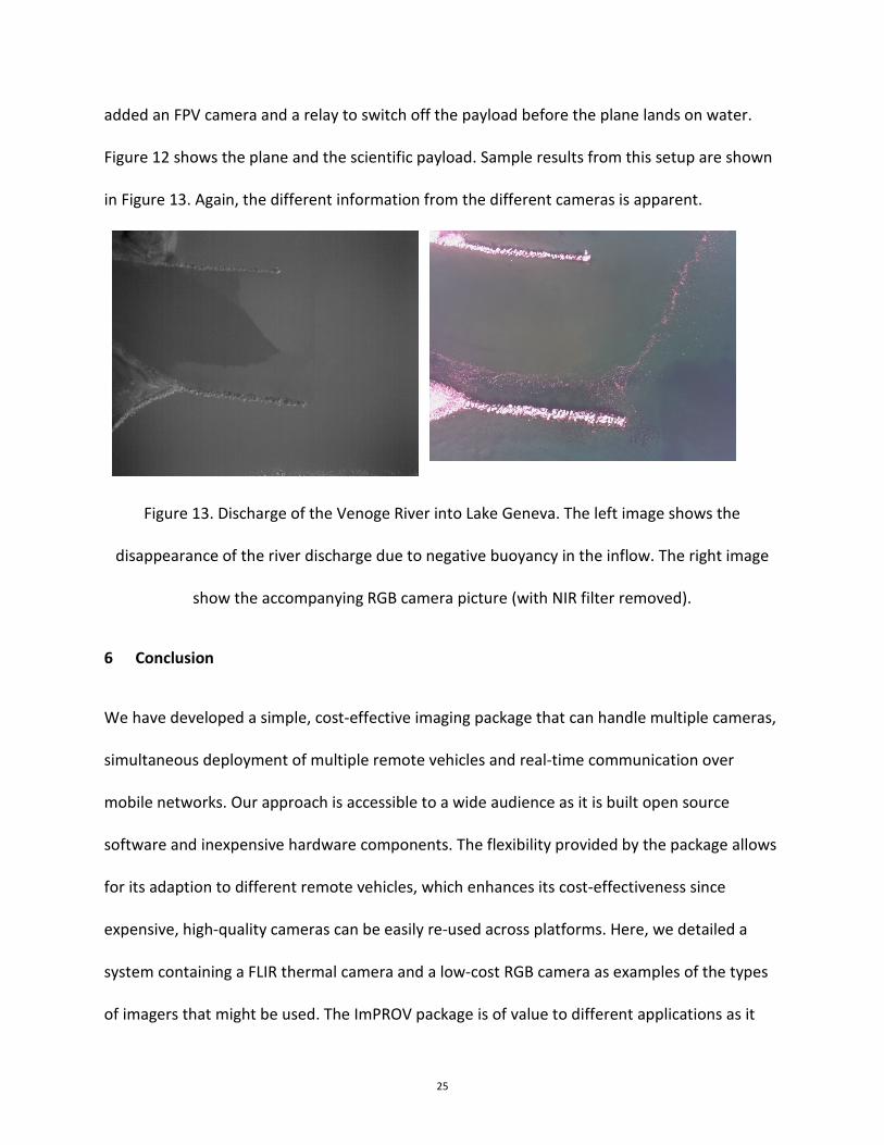
added an FPV camera and a relay to switch off the payload before the plane lands on water.
Figure 12 shows the plane and the scientific payload. Sample results from this setup are shown
in Figure 13. Again, the different information from the different cameras is apparent.
Figure 13. Discharge of the Venoge River into Lake Geneva. The left image shows the
disappearance of the river discharge due to negative buoyancy in the inflow. The right image
show the accompanying RGB camera picture (with NIR filter removed).
6 Conclusion
We have developed a simple, cost-effective imaging package that can handle multiple cameras,
simultaneous deployment of multiple remote vehicles and real-time communication over
mobile networks. Our approach is accessible to a wide audience as it is built open source
software and inexpensive hardware components. The flexibility provided by the package allows
for its adaption to different remote vehicles, which enhances its cost-effectiveness since
expensive, high-quality cameras can be easily re-used across platforms. Here, we detailed a
system containing a FLIR thermal camera and a low-cost RGB camera as examples of the types
of imagers that might be used. The ImPROV package is of value to different applications as it
26
offers LTE communication. Given the ubiquitous presence of LTE coverage worldwide, ImPROV
solutions have no range constraints beyond those imposed by the host remote vehicle, so
beyond-line-of-sight deployments are feasible. Live streaming of the imagery improves
operational safety, and enhances mission efficiency since the operator can modify the mission
in real-time if the imagery finds features of particular interest. Besides imagers, other sensors
can be attached to the ImPROV system and, with some modifications, also live-streamed. We
have used this package successfully on several different platforms, with in-house built
structural components made with a small 3D printer. The ImPROV hardware setup is
unchanged for each remote vehicle, except for minimal software changes.
Acknowledgements
The development of ImPROV benefited from numerous persons working on different research
and engineering projects both directly and indirectly relying on sensing from remote vehicles
and installations. We offer our thanks to Philippe Paccaud, Beat Geissmann, Nawaaz Guijja
Shaik, Ulrich Lemmin, and Abolfazl Irani Rahaghi. Partial financial support was provided by SNF
159422.
7 References
Bin, H., & Amahah, J. (2009). The design of an unmanned aerial vehicle based on the ArduPilot.
Indian Journal of Science and Technology, 2(4), 12-15.
doi:10.17485/ijst/2009/v2i4/29423
27
Colomina, I., & Molina, P. (2014). Unmanned aerial systems for photogrammetry and remote
sensing: A review. ISPRS Journal of Photogrammetry and Remote Sensing, 92, 79-97.
doi:10.1016/j.isprsjprs.2014.02.013
Gonzalez-Aguilera, D., & Rodriguez-Gonzalvez, P. (2017). Drones—An Open Access Journal.
Drones, 1(1), 1. doi:10.3390/drones1010001
Liardon, J.-L., & Barry, D. A. (2017). Freedom from wired networks: Wireless internet
communications with 3G/4G. Submitted.
Lizarazo, I., Angulo, V., & Rodríguez, J. (2017). Automatic mapping of land surface elevation
changes from UAV-based imagery. International Journal of Remote Sensing , 38(8-10),
2603-2622. doi:10.1080/01431161.2016.1278313
Manley, J. E. (2008). Unmanned surface vehicles, 15 years of development. OCEANS 2008 (p.
Article number 5152052). Quebec City, Canada: IEEE.
doi:10.1109/OCEANS.2008.5152052
Manley, J. E. (2016). Unmanned maritime vehicles, 20 years of commercial and technical
evolution. Oceans 2016 (p. art. no. 7761377). Monterey USA: IEEE.
doi:10.1109/OCEANS.2016.7761377
Pádua, L., Vanko, J., Hruška, J., Adão, T., Sousa, J. J., Peres, E., & Morais, R. (2017). UAS, sensors,
and data processing in agroforestry: A review towards practical applications.
International Journal of Remote Sensing, 38(8-10), 2349-2391.
doi:10.1080/01431161.2017.1297548
28
Shi, Y., Thomasson, J. A., Murray, S. C., Pugh, N. A., Rooney, W. L., Shafian, S., . . . Yang, C.
(2016). Unmanned aerial vehicles for high-throughput phenotyping and agronomic
research. PLOS ONE, 11(7), e0159781. doi:10.1371/journal.pone.0159781
Zhao, J., Yan, W., & Jin, X. (2011). Brief review of autonomous surface crafts. ICIC Express
Letters, 5(12), 4381-4386. Retrieved from http://www.ijicic.org/el-5(12).htm