A Large Area Tactile Sensor Patch Based on Commercial Force Sensors
19
Sensors 2011, 11, 5489-5507; doi:10.3390/s110505489 sensors ISSN 1424-8220 www.mdpi.com/journal/sensors Article A Large Area Tactile Sensor Patch Based on Commercial Force Sensors Fernando Vidal-Verdú 1, *, Maria Jose Barquero 1 , Julián Castellanos-Ramos 1 , Rafael Navas-Gonzá lez 1 , Jose Antonio Sánchez 1 , Javier Serón 2 and Alfonso García-Cerezo 2 1 Department of Electronics, University of Má laga, Má laga 29071, Spain; E-Mails: [email protected] (M.J.B.); [email protected] (J.C.-R.); [email protected] (R.N.-G.); [email protected] (J.A.S.) 2 Departamento de Ingenierí a de Sistemas y Automá tica, University of Má laga, Má laga 29071, Spain; E-Mails: [email protected] (J.S.); [email protected] (A.G.-C.) * Author to whom correspondence should be addressed; E-Mail: [email protected]; Tel.: +34-952-133-325; Fax: +34-952-133-324. Received: 9 April 2011; in revised form: 11 May 2011 / Accepted: 17 May 2011 / Published: 19 May 2011 Abstract: This paper reports the design of a tactile sensor patch to cover large areas of robots and machines that interact with human beings. Many devices have been proposed to meet such a demand. These realizations are mostly custom-built or developed in the lab. The sensor of this paper is implemented with commercial force sensors. This has the benefit of a more foreseeable response of the sensor if its behavior is understood as the aggregation of readings from all the individual force sensors in the array. A few reported large area tactile sensors are also based on commercial sensors. However, the one in this paper is the first of this kind based on the use of polymeric commercial force sensing resistors (FSR) as unit elements of the array or tactels, which results in a robust sensor. The paper discusses design issues related to some necessary modifications of the force sensor, its assembly in an array, and the signal conditioning. The patch has 16 × 9 force sensors mounted on a flexible printed circuit board with a spatial resolution of 18.5 mm. The force range of a tactel is 6 N and its sensitivity is 0.6 V/N. The array is read at a rate of 78 frames per second. Finally, two simple application examples are also carried out with the sensor mounted on the forearm of a rescue robot that communicates with the sensor through a CAN bus. OPEN ACCESS
Transcript of A Large Area Tactile Sensor Patch Based on Commercial Force Sensors

Sensors 2011, 11, 5489-5507; doi:10.3390/s110505489
sensors ISSN 1424-8220
www.mdpi.com/journal/sensors
Article
A Large Area Tactile Sensor Patch Based on Commercial Force
Sensors
Fernando Vidal-Verdú 1,*, Maria Jose Barquero
1, Julián Castellanos-Ramos
1,
Rafael Navas-González 1, Jose Antonio Sánchez
1, Javier Serón
2 and Alfonso García-Cerezo
2
1 Department of Electronics, University of Málaga, Málaga 29071, Spain;
E-Mails: [email protected] (M.J.B.); [email protected] (J.C.-R.);
[email protected] (R.N.-G.); [email protected] (J.A.S.) 2 Departamento de Ingeniería de Sistemas y Automática, University of Málaga, Málaga 29071,
Spain; E-Mails: [email protected] (J.S.); [email protected] (A.G.-C.)
* Author to whom correspondence should be addressed; E-Mail: [email protected];
Tel.: +34-952-133-325; Fax: +34-952-133-324.
Received: 9 April 2011; in revised form: 11 May 2011 / Accepted: 17 May 2011 /
Published: 19 May 2011
Abstract: This paper reports the design of a tactile sensor patch to cover large areas of
robots and machines that interact with human beings. Many devices have been proposed to
meet such a demand. These realizations are mostly custom-built or developed in the lab.
The sensor of this paper is implemented with commercial force sensors. This has the
benefit of a more foreseeable response of the sensor if its behavior is understood as the
aggregation of readings from all the individual force sensors in the array. A few reported
large area tactile sensors are also based on commercial sensors. However, the one in this
paper is the first of this kind based on the use of polymeric commercial force sensing
resistors (FSR) as unit elements of the array or tactels, which results in a robust sensor. The
paper discusses design issues related to some necessary modifications of the force sensor,
its assembly in an array, and the signal conditioning. The patch has 16 × 9 force sensors
mounted on a flexible printed circuit board with a spatial resolution of 18.5 mm. The force
range of a tactel is 6 N and its sensitivity is 0.6 V/N. The array is read at a rate of 78 frames
per second. Finally, two simple application examples are also carried out with the sensor
mounted on the forearm of a rescue robot that communicates with the sensor through
a CAN bus.
OPEN ACCESS

Sensors 2011, 11
5490
Keywords: tactile sensors; assistive robots; human-machine interaction; force sensing
resistors
1. Introduction
Tactile sensors are basically arrays of force sensors that enable a whole specific surface area to be
monitored, instead of only discrete point pressure monitoring. They are demanded in applications
where unstructured environments or uncertainty are present, such as minimally invasive surgery (MIS),
robotics, rehabilitation, virtual reality, telepresence, or industrial automation [1]. Many different
approaches have been proposed to manufacture these sensors, most of them are based on piezoresistive
or capacitive principles, and a few are based on optical or piezoelectrical transduction [2]. Many of
these sensors are made with silicon or polymers using microelectromechanical systems (MEMS)
technologies. These technologies are not oriented to large area devices, so they are usually proposed
for applications that demand high spatial resolution and good performance in terms of errors, such as
MIS. However, large area devices can be made with skin patches, i.e., by connecting several arrays in
more complex structures. For instance, a piezoresistive MEMS on polymer sensor that covers an area
of 25 mm × 25 mm is presented in [3]. The scalability to larger sensors is limited by the wiring
complexity and the authors proposed the addition of silicon based integrated circuits on the same
substrate to achieve a modular and large area sensor. Another modular approach based on capacitive
MEMS on polymer is examined in [4]. Other implementations build a sensor with MEMS on silicon
and soldered in an array on a flexible PCB [5]. Nevertheless, those sensors that are not oriented to
cover the fingertips but for example the forearms, do not require a high spatial resolution and are
usually developed with other technologies.
Optical tactile sensors are composed of photo emitter and photo detector pairs. Pressure against the
sensor modulates the light that is captured by the detector. A skin that covers the whole surface of a
robot and allows a safe interaction with humans is presented in [6]. It is made with infrared LED and
detector pairs that implement proximity sensors. In [7] a module is presented with 32 tactels that are
based on a LED, a phototransistor and a urethane foam atop. The amount of light scattered in the foam
and detected by the phototransistor depends on the pressure exerted on the tactel. Quite high hysteresis
is observed. In [8] sensors based on fiber Bragg gratings are proposed. The pressure causes a shift in
the wavelength of the Bragg grating. The tactels have good sensitivity, repeatability and no hysteresis.
However, each tactel has its own Bragg wavelength, which is a drawback to building large arrays (the
paper shows results from small arrays of 3 × 3 elements), and the electronics are complex.
Capacitive tactile sensors exploit the dependence of the capacitance on the distance between the
plates of a capacitor that has a deformable dielectric layer. Parasitic capacitors and noise are major
concerns, so signal conditioning must be close to the raw sensor. Conformable and stretchable
capacitive tactile sensors are commercialized by Pressure Profile Systems [9]. In [10] a modular
approach is proposed where triangular modules of 12 capacitive tactels are connected to each other to
cover any shape. An off-the-shelf CDC capacitive to digital converter (AD7147) standard chip from
Analog Devices is used for signal conditioning in every module. A common drawback of tactile

Sensors 2011, 11
5491
capacitive sensors is hysteresis. However in [11] a sensor is presented that has no hysteresis. This is
achieved by an appropriate selection of the elastomer between capacitor plates. Signal conditioning is
carried out with multivibrators made with off-the shelf integrated circuits.
The last and larger group of sensors reported to cover large areas are those based on piezoresistive
principles. Several are made of conductive fabric or rubbers [12,13]. A common method of producing
these sensors consists in implementing an array of electrodes on a flexible printed circuit board, and a
conductive rubber or polymer is placed atop of them [14,15]. QTC (Quantum Tunneling Composite)
from Peratech is used in [16] to build the array (64 tactels in the forearm) of custom sized sensors cut
from A4 size sheets. Wiring is again a concern here. The EIT (Electrical Impedance Tomography)
technique is used in [17] to implement a stretchable tactile sensor that has electrodes only at the
contour, thus wiring is reduced. However, tactile sensors based on EIT are less accurate and the
procedure to read the data from them is quite slow. A sensor is proposed in [18] that communicates
through microwaves in a two dimensional sheet. It implements a RFID tag and a resonant proximity
connector in every tactel and the whole array detects binary images (it does not register pressure
maps). The sensor in [19] also provides a binary output and points to a printing technology plus
multiplexing to reduce the number of external wires. The sensor in [20] is also made with a large-area
printing technology and addressing is done with a switching matrix of organic field-effect transistors
implemented on the same substrate. This is a promising technology, although the estimated scan time
in a 16 × 16 array is 480 ms.
Other authors take advantage of the low spatial resolution of the tactile sensor and relatively large
size of the tactel to implement it with a commercial force sensor. In [21] this approach is adopted with
silicon based force sensors. These sensors have good performance in terms of drift, hysteresis or
linearity. However, pieces of elastic material are used to concentrate the force at the diaphragms of the
pressure-sensing elements and another elastic sheet is used to make the sensor soft and perform a
spatial filtering. The addition of these elastic materials degrades somewhat the performance. Moreover,
silicon is fragile and brittle in comparison to other materials like polymers. In [22] polymeric FSRs
(Force Sensing Resistors) are used as on-off sensors in combination with force-torque sensors to
compute the magnitude and direction of the force and the contact position. However, it is assumed that
a simple force is applied, so its application is limited when more complex forces are exerted and more
detailed information is required, as in the case of holding a human being in the arms of the robot.
Similar sensors have been used to provide some tactile sensitivity to robotic hands in [23], where they
are not used as binary sensors but the whole output force range is exploited. Only a few of these
sensors are necessary in [23] and they are wisely located in the robotics hands.
This paper presents a large area tactile sensor that is made of the same commercial FSRs soldered
on a flexible Printed Circuit Board (PCB). Some preliminary results were presented in [24]. Many
problems arise when these FSRs are intended to be used in this way. Some modifications have to be
made to the sensor to preserve its performance and behavior as an isolated element. The paper explains
these modifications and the strategies followed to build the patch and minimize errors and
interferences. The obtained tactel is characterized and results for the input-output curve, drift, step
response and mismatching are shown in the paper. The force range of the tactel is 6 N and its
sensitivity is 0.6 V/N. The patch has 16 × 9 tactels with a spatial resolution of 18.5 mm and it is read at
a rate of 78 frames per second. Signal conditioning is based on a PIC18F4680. A modular approach is

Sensors 2011, 11
5492
achieved in this way since communication with a CAN bus is also implemented, so many of these or
similar patches can be connected. Two application examples were also carried out where the sensor
was used to cover the forearm of the ALACRANE rescue robot [25]. Details are given at the end of
the paper.
2. Specifications of the Sensor
As a reference to design the sensor, we are interested in avoiding violent collisions that can hurt
humans. When a human being comes into contact with the surface of an object the amount of force
produced is typically around 0.1–2.0 N and this force can be taken as a reference for the minimum
value to be detected and does not cause any pain. Regarding maximum force, the average pressure
exerted against the skin by the weight of a body held in the arms is around 14 kPa (0.15 Kg/cm2
aprox.) and a certain security margin must be taken [21]. The response time in which a human
completes all processing of tactile stimuli from contact detection to response output is 100–200 ms.
This is taken in [22] as a reference of the input-output delay of the smart tactile sensor. As regards to
the spatial resolution, the static simultaneous two-point discrimination threshold of the human skin in
the forearm is around 38 mm [26]. In the following section we will describe the design of a sensor that
meets these specifications. Design issues related to the raw sensor and electronics are discussed.
3. Design of the Raw Sensor
As mentioned in the introduction, our design is based on commercial force sensing resistors (FSR).
Three commercial FSRs from Lusense, Tekscan (Flexiforce sensors) and Interlink Electronics are on
the market. These sensors have been compared in [27] and [28]. The FSRs from Interlink [29] are the
most robust, and this is an important point in our design because of the hostile environment and heavy
weights which the robot has to cope with. Moreover, these sensors have a good tradeoff between drift,
hysteresis and accuracy. A few different sensors are available from Interlink Electronics, two round in
shape, one square and another strip shaped one. Round sensors are more suitable for forming our array.
The larger one was chosen (Interlink Electronics Standard 402 FSR) [29] because it allows the
resolution requirements to be accomplished of less than 38 mm between tactels. In addition it also fits
our force requirements. Table 1 lists the main performance data of this sensor.
Table 1. Interlink Electronics Standard 402 FSR Main Features.
Size 18.28 mm (diameter)
Actuation Force 0.1 N
Durability 10 Million actuations without failure
Force Sensitive Range 0.1–10 N
Force Repeatability 0.2% (single part)
0.6% (part to part)
Hysteresis +10%
Operating temp. range −30 °C to 70 °C

Sensors 2011, 11
5493
We had to decide how to arrange the sensors in a flexible sheet that is shaped as a cylinder when
placed in its final destination. In order to have the best filling factor, we decided to arrange them in a
triangular grid (see Figure 1(a)).
A slight, but significant, modification of the sensor refers to the spacer the commercial sensor has
between the layer with the electrodes and the flexible substrate with printed semi-conductor (see
Figure 1(b)). This spacer guarantees that there is no response in absence of force applied to the sensor.
However, the presence of this spacer causes no response even in the case that a flat rigid object presses
the sensor, because it avoids the contact between the substrate and the electrodes. This is observed
clearly in our sensor. It does not register any data with the above described array of FSRs. Some
element must be added atop to allow the force to reach the active area of the sensor, which is the inner
area beyond the spacer. A possible solution we have adopted is the addition of small polyurethane cones
(circular bumpers BS-01R, Durometer, Shore A 60–70 Standard [30]) atop each FSR, as Figure 1(c,d)
illustrate. Trials with continuous sheets of deformable materials were also made. The conclusion was
that the response depends greatly on the properties of the material. We registered readings with quite
flexible foams but not with other more rigid elastomers atop the sensor. With a single piece of
elastomer per sensing resistor, any pressure exerted against a tactel is translated by the cone directly to
the active area of the FSR. Moreover, this approach allows the characterization as an isolated element.
Figure 1. (a) Detail of the grid. (b) Layers in a Force Sensing Resistors from Interlink.
(c) Draw of the sensor with a polyurethane cone atop. (d) A photograph.
(a) (b)
(c) (d)
The influence of the added cone on the performance of the sensor was tested with some
experiments. We used the characterization set-up of Figure 2(a). Basically, it consists of a translation
stage (A) to place the sensor on, a stepper motor (B) to exert the force via a spring (C) and finally a
force sensor placed at the tip of the probe (D) (Honeywell FSG15N1A). The measurement process is
automatic and it is controlled by a computer. The computer sends the commands to the motor and
reads the data from the sensor by means of a data acquisition board. The system is calibrated before
making the measurements. It is done by pressing with the probe against a precision balance
(KERN 440-47N) and taking the readings from the balance and from the characterization set-up to
obtain the calibration curve in Figure 2(b).

Sensors 2011, 11
5494
Figure 2. (a) Characterization set-up. (b) Calibration curve.
(a) (b)
A first simple test to know the influence of the polyurethane cone was carried out. It consisted of
repeating the calibration procedure but placing a cone between the probe and the balance. The curve
obtained is shown in Figure 3. The larger the difference between this curve and the calibration curve in
Figure 2(b), the larger the influence of the cone would be. Since this difference is negligible, we can
conclude that the piece of polyurethane does not introduce a significant disturbance in terms of
hysteresis or linearity.
Figure 3. Data obtained when the probe presses against a polyurethane cone placed on the balance.
Another test was done with the cone atop of one sensing resistor, and both attached on a rigid and
flat surface. The data registered by the set-up in Figure 2(a) is shown in Figure 4(a,b). On the left, the
readings from ten cycles of increasing and decreasing force are shown while the figure on the right
depicts the mean value and standard deviation obtained from this data. The same measurement was
made but replacing the polyurethane cone with a circular piece of metal and a small piece of fabric at
the interface with the sensor to achieve a uniform contact pressure. The results are in Figure 4(c,d),
0 1 2 3 4 5 6 7-0.5
0
0.5
1
1.5
2
2.5
3
3.5
4
4.5
Force (N)
Ou
tpu
t o
f th
e p
rob
e s
en
so
r (V
)
Force up
Force down
0 1 2 3 4 5 6 7-0.5
0
0.5
1
1.5
2
2.5
3
3.5
4
4.5
Force (N)
Ou
tpu
t o
f th
e p
rob
e s
en
so
r (V
)
Force up
Force down

Sensors 2011, 11
5495
where the meaning of data is the same as in Figure 4(a,b). The curves are also very similar this time,
with no significant differences in terms of errors. The gain is slightly larger in the case of the circular
piece, but it is because its diameter is 11.5 mm while the diameter of the basis of the cone
is 10.2 mm. The diameter of the active area of the sensing resistor is 12.7 mm, so a cone that fitted this
area would perform better.
Figure 4. (a and b) Static response to a pressure up—pressure down cycle of the modified
sensor with the cone atop of one sensing resistor. (c and d) Static response of the sensor
without the polyurethane cone and pressed with a circular piece of metal and a small piece
of fabric at the interface with the sensor to achieve a uniform contact pressure.
(a) (b)
(c) (d)
Two additional tests were made to establish the dynamic response of the modified sensor. FSRs
have a rise time between 1–2 ms determined by their mechanical design. A simple test was made to
assure the modification with the polyurethane cone did not change this dynamic response. Figure 5
shows the response to a force pulse measured by the silicon force sensor (top curve) and by the
modified FSR (bottom curve). Responses are in the order of hundreds of microseconds, so they do not
0 1 2 3 4 5 60
0.5
1
1.5
2
2.5
3
3.5FSR interlink with a polyurethane cone
Force (N)
Ou
tpu
t (V
)
Force up
Force down
0 1 2 3 4 5 60
0.5
1
1.5
2
2.5
3
3.5
Force (N)
Ou
tpu
t (V
)
FSR interlink with a polyurethane cone
Force up
Force down
0 1 2 3 4 5 60
0.5
1
1.5
2
2.5
3
3.5FSR interlink with a circular metal piece
Force (N)
Ou
tpu
t (V
)
Force up
Force down
0 1 2 3 4 5 60
0.5
1
1.5
2
2.5
3
3.5
Force (N)
Ou
tpu
t (V
)
FSR interlink with a circular metal piece
Force up
Force down
Sensors 2011, 11
5496
determine the limitation of the dynamic response of the sensor to meet a delay below 200 ms. This
limitation will be given by the electronics discussed in the next section.
Figure 5. Tactel response to a force pulse. Channel 1 shows the output from the probe
silicon force sensor and Cannel 2 shows the output from the tactel.
Regarding drift, we have followed a procedure similar to that reported in [28] for a characterization
of commercial force sensors based on similar principles. This procedure consists in measuring the drift
not only when pressure is exerted on the sensor from a prior situation of no pressure on it, but also the
result of a few increments from starting pressure different to zero. We also show results of positive as
well as negative increments. Figure 6 shows the results of this experiment that was performed with the
set-up in Figure 2(a). A drift of up to 10.7% of the full scale output in 1,974 s is observed in the worst
case. The largest drift is observed when the starting pressure is zero. This effect could be reduced by
applying a preload.
Figure 6. Measured drift of a tactel.
0 200 400 600 800 1000 1200 1400 1600 1800 20000
1
2
3
4
5
Time (s)
Ou
tpu
t (V
)
FSR interlink with a silicone cone
input 2,07 N from 0 N
input 4,04 N from 2,07 N
input 5,21 N from 4,04 N
input 4,04 N from 5,21 N
input 2,07 N from 4,04 N

Sensors 2011, 11
5497
The FSR sensors from Interlink also have long leads with the connectors at their ends. These
connectors are crimped because the leads are damaged by the heat and cannot be soldered directly to
the PCB. As a consequence, the distance between FSRs in the array is very large unless we allow they
overlap. We could cut the leads and crimp them again, but this would take a long time. Moreover, it is
not possible to remove them completely and the distance between tactels would be always larger than
if the force sensors overlap. Therefore, active areas of the sensors lie on the leads of others (see Figure 7)
and the spatial resolution is optimum.
Figure 7. (a) Detail of the placement of the sensors, and (b) a photograph of the whole array.
(a) (b)
Two more practical issues are important to discuss here. First, we observed that interferences appear
despite the electronic (described in the next section) being designed to cancel them. After
investigations we saw the contact of the sensor leads with solderings of other tactels caused such
interferences. Therefore, insulation of the solderings was required to remove them, as Figure 7(a)
shows. Figure 8 shows the reading of the sensor when it is pressed with a circular piece of metal with
and without insulating the solderings.
Figure 8. Tactile image of a circular object without (a) and with (b) insulating the solderings.
(a) (b)

Sensors 2011, 11
5498
The other implementation issue refers to the convenience of having a flat and firm surface under the
force sensing resistor. If the sensors are mounted as Figure 7 depicts and they rest on the tails of other
sensors, a poor performance is observed. For instance, Figure 9(a) shows the output obtained with the
characterization set-up of Figure 2(a) when the output from one of the mounted tactels is registered. A
highly non-linear and distorted output is obtained. Another modification of the sensor is required to
achieve an output similar to that reported by the manufacturer. It is done by attaching a circular rigid
plastic piece at the bottom of the sensor, as Figure 9(c) shows. In this way the output from the sensor is
quite linear, as Figure 9(b) shows.
Figure 9. (a) Tactel output without and (b) with a rigid flat piece at the bottom.
(c) Photograph of the modified FSR.
(a) (b)
(c)
Finally, another test was carried out to obtain information about the mismatching of the sensors in
the array, as in [21]. The output of 16 tactels was read with the set-up in Figure 2(a) and the results are
shown in Table 2. The variations could be tolerated for practical purposes [1], or some calibration
procedure can be implemented that takes advantage of the microcontroller of the sensor.
0 1 2 3 4 5 60
0.5
1
1.5
2
2.5
3
3.5Without a rigid flat piece at the bottom
Force (N)
Outp
ut
(V)
0 1 2 3 4 5 60
0.5
1
1.5
2
2.5
3
3.5With a rigid flat piece at the bottom
Force (N)
Outp
ut
(V)

Sensors 2011, 11
5499
Table 2. Variations of Tactels.
Tactel coordinates Gain (Volts/N)
(5,1) (5,3) (5,7) (5,9) (6,9) (6,8) (6,3) (6,2) (5,2) (5,4) (5,6) (5,8) (5,10) (5,11) (6,11) (6,1)
0.57 0.63 0.65 0.59 0.62 0.68 0.55 0.65 0.55 0.65 0.69 0.61 0.55 0.57 0.57 0.47
Average S.D.
0.60 0.06
4. Design of the Electronics
Figure 10(a) shows the local electronics of the smart tactile sensor. It is based on a microcontroller
PIC18F4680 and is in charge of scanning the array, storing the data and sending it via CAN bus to a
central processing unit. More capabilities can be added to the smart sensor by taking advantage of the
microcontroller. Figure 10(b) shows a basic schematic of the main blocks in Figure 10(a) except the
power supply module. The array is scanned and every tactel output is read.
The output voltage is given by the following expression:
ref
ij
Gout V
R
RV )1(
where Rij is the force dependant resistance of the element ij in the array, and RG is the resistance to set
the gain of the transresistance amplifiers at the output of every column.
Figure 11 shows the readings of the smart tactile sensor when its surface is pressed with the hand.
The shape of the hand is clearly noticeable and the information about the existence of contact as well
as the force exerted is provided.
Figure 10. (a) Photograph of the electronics. (b) simplified schematics.
(a)

Sensors 2011, 11
5500
Figure 10. Cont.
(b)
Figure 11. (a) and (b) two tactile images of a hand as registered by the tactile sensor.
(a) (b)
Note that one operational amplifier is required per column in Figure 10(b). Their purpose is to set
the voltage Vref at the tracks of all columns. Since the voltage of all rows that do not contribute to the
output is also set to Vref, any possible parasitic path is short circuited. This is a common grounding
technique [31] in sensors developed from a continuous film of conductive rubber or polymer because
parasitic resistors are present between tactels. We think it is worth highlighting here that these
electronics must be used even when we have a discrete array. This is true in our case, because we have
an array of force sensors. Nevertheless, once they are arranged in rows and columns and connected by
the corresponding addressing tracks, multiple parasitic paths appear. One of them is depicted in
Figure 12(a), where a simpler electronics layout that does not cancel the interferences is shown. The
left part of Figure 12 shows the readings provided by this electronics. Note that crosstalk makes the
shape of the hand indistinguishable and it is not possible to determine the orientation and size of the

Sensors 2011, 11
5501
object on the sensor. Similarly, the implementation in [32] describes a technique where tactile sensors
are formed by dispensing conductive polymer on copper electrodes. This is highlighted as a technique
to reduce crosstalk, although grounding is also necessary.
Figure 12. (a) Electronics that does not cancel crosstalk and (b) tactile image obatined
from a hand on the sensor.
(a)
(b)
Regarding the sensor bandwidth, reading out the whole array takes 12.8 ms, so it is much lower
than the 100–200 ms we had set as a maximum. Moreover, distance between centers of tactels is 1.85 cm
(see Figure 7(b)), so it is also lower that 3.8 cm which we had set as a goal taking into account the
static spatial resolution of the human skin in the forearm. Finally, Table 3 shows data from the
proposed sensor and from other reported tactile sensor patches oriented to cover large areas.

Sensors 2011, 11
5502
Table 3. Performance data from the proposed and other reported tactile sensor patches.
Author/
Year
Transd.
Method Tech.
N° of Sensing
Elements
Spatial
Resol.
Sensor
BW
Force/Press.
Range
Force/Press.
Sensitivity
Ohmura [7]/
2006 Optical
Flexible
PCB 8 × 4 ~30 mm 5 kHz 500 kPa
Shan [5]/
2005 Piezores.
MEMS on Si,
Flex.PCB 4 × 4 10 mm 2 N
228 mV/N
(shear forces:
34 mV/N)
Heo [8]/
2006 Optical 3 × 3 5 mm 5 N 1 mN
Cannata [10]/
2008 Capacitive
Flexible
PCB
12
(triangular patch) 2 tactels/cm
Up to
0.5 kHz
Ulmen [11]/
2010 Capacitive
Foam Layer
PCB 4 × 4 15 mm 0.080 kHz 100 N 0.02 N
Shimojo [13]/
2004
Conduct.
Rubber 16 × 3 3 mm 12 N 0.2 MPa
Kerpa [14]/
2003 Piezores. PCB 10 × 23 15 mm 0.040 kHz 120 kPa 12 bits
Someya [20]/
2004 FSR Organic FET 16 × 16 2.54 mm 0.003 KHz 30 kPa
Mukai [21]/
2008
Silicon
based FSR Flexible PCB 8 × 8 18 mm 0.1 kHz 128 kPa
Sthiel [23]/
2006
FSR
(QTC) PCB 4 × 2
Proposed Polymer
based FSR
Flexible
PCB 16 × 9 18.5 mm 0.078 kHz 6 N 0.60 V/N
5. The Sensor in a Robot
Figure 13(c) shows the sensor mounted on the arm of the rescue robot ALACRANE. This is a fully
hydraulic robot that has been developed from a modified small demolition machine by Brokk®
. The
Main Arm has five DOF with five hydraulic cylinders. This redundant configuration increases its
reachability of the end-effector. Its payload is 120 kg when it is fully extended, and 450 kg in the
vicinity of the arm base.
An experiment has been carried out to show the performance of the sensor in this rescue robot. The
robot has been programmed with the following reactive behavior. If contact is detected while it is
doing some task, the manipulator moves back a predefined distance from the trajectory it was
following. If there is no contact at this moment, the robot resumes the task. If there is still contact, the
robot keeps still until the contact ceases.
Figure 13 illustrates this behavior. It shows the Cartesian coordinates x, y, z, referred to the base
reference system of the robot as well as the average force registered by the tactels whose readings are
higher than a certain threshold. Figure 13(a) shows a circular trajectory followed by the manipulator
when no contact is detected, while Figure 13(b) shows the described reactive behavior when the
manipulator makes contact with an obstacle twice. The first time the contact remains even when the

Sensors 2011, 11
5503
manipulator has moved back, and the second time the contact is undone before the manipulator
completes the backward movement, therefore the robot resumes its task. This behavior would keep
people safe as well as objects surrounding the rescue robot and the robot itself.
Figure 13. (a) Trajectories of the manipulator without contact, and (b) with two contacts.
(c) Sensor mounted on the ALACRANE (the top right corner of the figure shows a detail
where the sensor was mounted in a circular shape).
(a) (b)
(c)
Another experiment was carried out to illustrate the applicability of the sensor. This time the robot
takes the coordinates of the center of mass of the tactile image (Cx, Cy) to follow a certain trajectory.
These coordinates are calculated by the microcontroller of the tactile patch as:
,
(1)
where ( ) are the coordinates of the i-th tactel, is the force registered by it, and N is the number
of tactels in the tactile sensor. Note that the obtained result takes into account the contact area and also
the pressure distribution on this area. The trajectories of the center of mass when a dummy human is
held in the arms of a robot are shown in [20] to illustrate the use of the sensor. Here we show the
trajectory of the mass center and also how the robot can use this information in a cooperative task with
a human. Figure 14 shows the starting situation (A), where a metal tube is held by the arm of the robot
0 10 20 30 40 50 60-800
-600
-400
-200
0
200
400
600
800
Time (s)
Thre
e a
xis
positio
n (
mm
), S
ensor
Measure
ments
X axis
Y axis
Z axis
Sensor
0 20 40 60 80 100 120-800
-600
-400
-200
0
200
400
600
800
1000
Time (s)
Thre
e a
xis
positio
n (
mm
), S
ensor
Measure
ments
X axis
Y axis
Z axis
Sensor
Sensors 2011, 11
5504
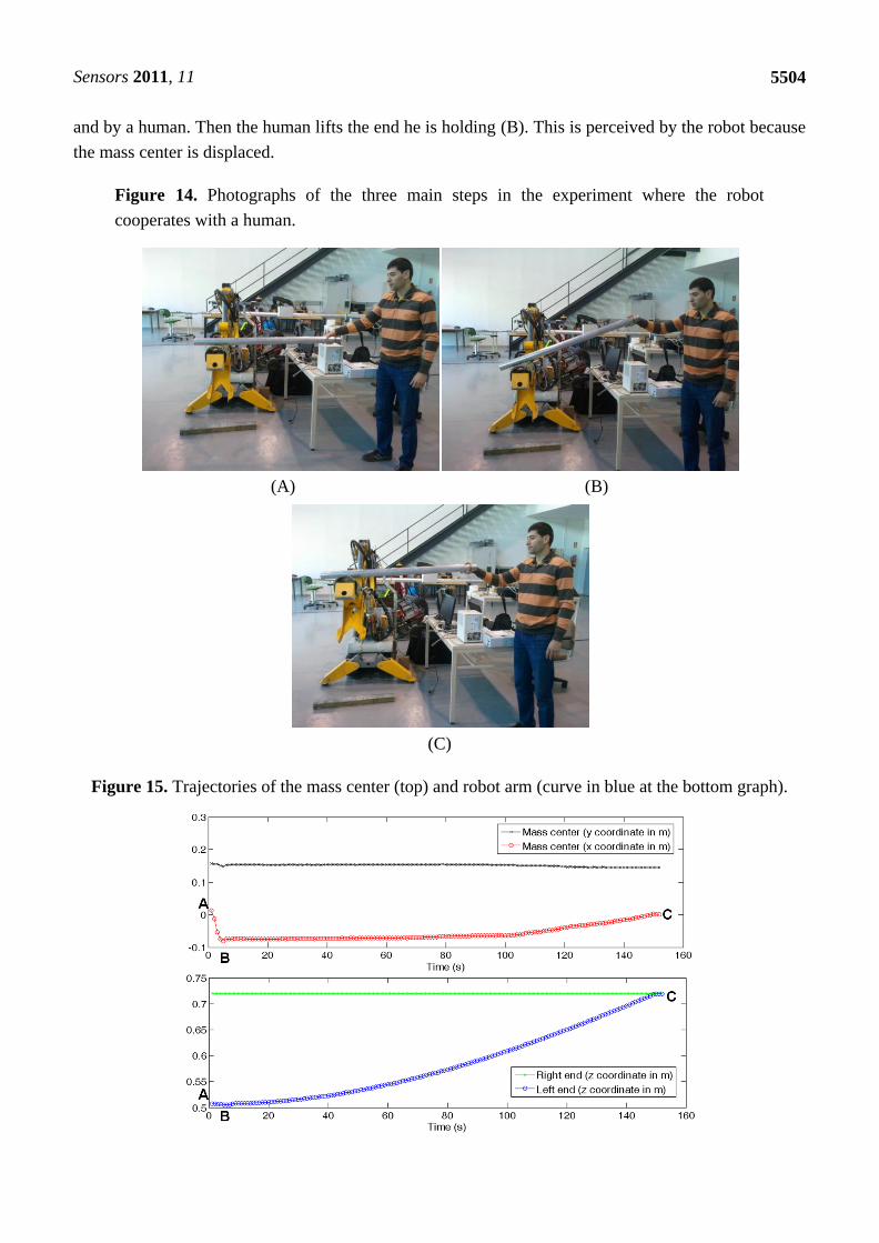
and by a human. Then the human lifts the end he is holding (B). This is perceived by the robot because
the mass center is displaced.
Figure 14. Photographs of the three main steps in the experiment where the robot
cooperates with a human.
(A) (B)
(C)
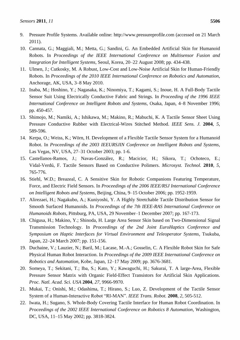
Figure 15. Trajectories of the mass center (top) and robot arm (curve in blue at the bottom graph).

Sensors 2011, 11
5505
This can be seen in Figure 15, where the trajectories of the center of mass and the robot arm are
depicted. Now the robot lifts its arm until the location of the center of mass goes back to the initial
value in (A). At this point, the heights of both ends of the tube are similar again (C), as can be seen in
Figures 14 and 15.
6. Conclusions
A thorough description of the design of a large area tactile sensor has been presented. It is the first
of this kind based on polymeric commercial force sensing resistors. This choice was made to achieve a
robust design in a shorter time. Some modifications were needed to maintain the performance of the
isolated force sensor, once it is incorporated to the tactile array on a flexible substrate. These
modifications are explained as well as their impact on the response of the sensor. We can see the latter
is negligible for good design practices that are discussed in the text. The performance of the sensor is
shown through many experimental measurements of the tactel response as well as of the tactile sensor
output. Finally, two examples illustrate its use in a rescue robot.
Acknowledgements
This work has been partially funded by the Spanish Government under contracts TEC2009-14446
and DPI2008-00553.
References
1. Lee, M.H. Tactile Sensing, New Directions, New Challenges. Int. J. Robot. Res. 2000, 7, 636-643.
2. Dahiya, R.S.; Metta, G.; Valle, M.; Sandini, G. Tactile Sensing—From Humans to Humanoids.
IEEE Trans. Robot. 2010, 1, 1-19.
3. Engel, J.; Chen, N.; Tucker, C.; Liu, C.; Kin, S.-H.; Jones, D. Flexible Multimodal Tactile
Sensing System for Object Identification. In Proceedings of the 5th IEEE Conference on Sensors,
Daegu, Korea, 22–25 October 2006; pp. 563-566.
4. Lee, H.-K.; Chang, S.-I.; Yoon, E. A Flexible Polymer Tactile Sensor: Fabrication and Modular
Expandability for Large Area Deployment. J. Microelectromech. Syst. 2006, 6, 1681-1686.
5. Shan, J.H.; Mei, T.; Sun, L.; Kong, D.Y.; Zhang, Z.Y.; Ni, L.; Meng, M.; Chu, J.R. The Design
and Fabrication of a Flexible Three-Dimensional Force Sensor Skin. In Proceedings of the
IEEE/RSJ International Conference on Intelligent Robots and Systems, Edmonton, AB, Canada,
2–6 August 2005; pp. 1818-1823.
6. Um, D.; Stankovic, B.; Giles, K.; Hammond, T.; Lumelsky, V. A Modularized Sensitive Skin for
Motion Planning in Uncertain Environments. In Proceedings of the 1998 IEEE International
Conference on Robotics & Automation, Leuven, Belgium, 16–20 May 1998; pp. 7-12.
7. Ohmura, Y.; Kuniyoshi, Y.; Nagakubo, A. Conformable and Scalable Tactile Sensor Skin for
Curved Surfaces. In Proceedings of the 2006 IEEE International Conference on Robotics and
Automation, Orlando, FL, USA, 15–19 May 2006; pp. 1348-1353.
8. Heo, J.-S.; Chung, J.-H.; Lee, J.-J. Tactile Sensor Arrays Using Fiber Bragg Grating Sensors.
Sens. Actuat. A 2006, 126, 312-337.
Sensors 2011, 11
5506
9. Pressure Profile Systems. Available online: http://www.pressureprofile.com (accessed on 21 March
2011).
10. Cannata, G.; Maggiali, M.; Metta, G.; Sandini, G. An Embedded Artificial Skin for Humanoid
Robots. In Proceedings of the IEEE International Conference on Multisensor Fusion and
Integration for Intelligent Systems, Seoul, Korea, 20–22 August 2008; pp. 434-438.
11. Ulmen, J.; Cutkosky, M. A Robust, Low-Cost and Low-Noise Artificial Skin for Human-Friendly
Robots. In Proceedings of the 2010 IEEE International Conference on Robotics and Automation,
Anchorage, AK, USA, 3–8 May 2010.
12. Inaba, M.; Hoshino, Y.; Nagasaka, K.; Ninomiya, T.; Kagami, S.; Inoue, H. A Full-Body Tactile
Sensor Suit Using Electrically Conductive Fabric and Strings. In Proceeding of the 1996 IEEE
International Conference on Intelligent Robots and Systems, Osaka, Japan, 4–8 November 1996;
pp. 450-457.
13. Shimojo, M.; Namiki, A.; Ishikawa, M.; Makino, R.; Mabuchi, K. A Tactile Sensor Sheet Using
Pressure Conductive Rubber with Electrical-Wires Stitched Method. IEEE Sens. J. 2004, 5,
589-596.
14. Kerpa, O.; Weiss, K.; Wörn, H. Development of a Flexible Tactile Sensor System for a Humanoid
Robot. In Proceedings of the 2003 IEEURSJIN Conference on Intelligent Robots and Systems,
Las Vegas, NV, USA, 27–31 October 2003; pp. 1-6.
15. Castellanos-Ramos, J.; Navas-González, R.; Macicior, H.; Sikora, T.; Ochoteco, E.;
Vidal-Verdú, F. Tactile Sensors Based on Conductive Polimers. Microsyst. Technol. 2010, 5,
765-776.
16. Stiehl, W.D.; Breazeal, C. A Sensitive Skin for Robotic Companions Featuring Temperature,
Force, and Electric Field Sensors. In Proceedings of the 2006 IEEE/RSJ International Conference
on Intelligent Robots and Systems, Beijing, China, 9–15 October 2006; pp. 1952-1959.
17. Alirezaei, H.; Nagakubo, A.; Kuniyoshi, Y. A Highly Stretchable Tactile Distribution Sensor for
Smooth Surfaced Humanoids. In Proceedings of the 7th IEEE-RAS International Conference on
Humanoids Robots, Pittsburg, PA, USA, 29 November–1 December 2007; pp. 167-173.
18. Chigusa, H.; Makino, Y.; Shinoda, H. Large Area Sensor Skin based on Two-Dimensional Signal
Transmission Technology. In Proceedings of the 2nd Joint EuroHaptics Conference and
Symposium on Haptic Interfaces for Virtual Environment and Teleoperator Systems, Tsukuba,
Japan, 22–24 March 2007; pp. 151-156.
19. Duchaine, V.; Lauzier, N.; Baril, M.; Lacase, M.-A.; Gosselin, C. A Flexible Robot Skin for Safe
Physical Human Robot Interaction. In Proceedings of the 2009 IEEE International Conference on
Robotics and Automation, Kobe, Japan, 12–17 May 2009; pp. 3676-3681.
20. Someya, T.; Sekitani, T.; Iba, S.; Kato, Y.; Kawaguchi, H.; Sakurai, T. A large-Area, Flexible
Pressure Sensor Matrix with Organic Field-Effect Transistors for Artificial Skin Applications.
Proc. Natl. Acad. Sci. USA 2004, 27, 9966-9970.
21. Mukai, T.; Onishi, M.; Odashima, T.; Hirano, S.; Luo, Z. Development of the Tactile Sensor
System of a Human-Interactive Robot ―RI-MAN‖. IEEE Trans. Robot. 2008, 2, 505-512.
22. Iwata, H.; Sugano, S. Whole-Body Covering Tactile Interface for Human Robot Coordination. In
Proceedings of the 2002 IEEE International Conference on Robotics 8 Automation, Washington,
DC, USA, 11–15 May 2002; pp. 3818-3824.

Sensors 2011, 11
5507
23. Stiehl, W.D.; Lalla, L.; Breazeal, C. A Somatic Alphabet Approach to Sensitive Skin. In
Proceedings of IEEE International Conference on Robotics and Automation ICRA’04,
New Orleans, LA, USA, 26 April–1 May 2004; pp. 2865-2870.
24. Vidal-Verdú, F.; Barquero, M.J.; Serón, J.; García-Cerezo, A. Large Area Smart Tactile Sensor
for Rescue Robot. In Proceedings of IEEE International Workshop on Robotic and Sensor
Environments (ROSE09), Lecco, Italy, 6–7 November 2009; pp. 6-10.
25. Mobile Robotic Assistant for Exploration and Rescue Missions. Available online:
http://www.isa.uma.es/C8/Alacrane/default.aspx (accessed on 21 March 2011).
26. Weinstein, S. Intensive and Extensive Aspects of Tactile Sensitivity as a Function of Body Part,
Sex and Laterality. In The Skin Senses; Kenshalo, D.R., Ed.; Charles C. Thomas Publishing:
Springfield, IL, USA, 1968; pp. 195-218.
27. Hollinger, A.; Wanderley, M.M. Evaluation of Commercial Force Sensing Resistors. In
Proceedings of International Conference on New Interfaces for Musical Expression, Paris,
France, 4–8 June 2006.
28. Vecchi, F.; Freschi, C.; Micera, S.; Sabatini, A.; Dario, P.; Sacchetti, R. Experimental Evaluation
of Two Commercial Force Sensors for Applications in Biomechanics and Motor Control. In
Proceedings of the 5th Annual Conference of the International Functional Electrical Stimulation
Society, Aalborg, Denmark, 17–23 June 2000; pp. 44-54.
29. Interlink Electronics. Available online: http://www.interlinkelectronics.com/force_sensors/
(accessed on 21 March 2011).
30. Self-Adhesive Molded Polyurethane Bumpers. Available online: http://www.bumperspecialties.com
(accessed on 21 March 2011).
31. D’Alessio, T. Measurement Errors in the Scanning of Piezoresistive Sensors Arrays. Sens. Actuat.
A 1999, 72, 71-76.
32. Yang, Y.J.; Cheng, M.Y.; Chang, W.Y.; Tsao, L.C.; Yang, S.A.; Shih, W.P.; Chang, F.Y.;
Chang, S.H.; Fan, K.C. An Integrated Flexible Temperature and Tactile Sensing Array Using
PI-Copper Films. Sens. Actuat. A 2008, 143, 143-153.
© 2011 by the authors; licensee MDPI, Basel, Switzerland. This article is an open access article
distributed under the terms and conditions of the Creative Commons Attribution license
(http://creativecommons.org/licenses/by/3.0/).