
2465 Electrochemical Detector Operator’s GuideŁ Eteignez toutes les flammes se trouvant à...
226
Waters 2465 Electrochemical Detector Operator’s Guide 34 Maple Street Milford, MA 01757 71500246502, Revision B
Transcript of 2465 Electrochemical Detector Operator’s GuideŁ Eteignez toutes les flammes se trouvant à...

Waters 2465 Electrochemical Detector
Operator’s Guide
34 Maple Street Milford, MA 01757
71500246502, Revision B
2465OG.book Page i Wednesday, November 7, 2007 10:33 AM

2465OG.book Page ii Wednesday, November 7, 2007 10:33 AM
NOTICE
The information in this document is subject to change without notice and should not be construed as a commitment by Waters Corporation. Waters Corporation assumes no responsibility for any errors that may appear in this document. This document is believed to be complete and accurate at the time of publication. In no event shall Waters Corporation be liable for incidental or consequential damages in connection with, or arising from, the use of this document.
© 2002, 2007 WATERS CORPORATION. PRINTED IN THE UNITED STATES OF AMERICA. ALL RIGHTS RESERVED. THIS DOCUMENT OR PARTS THEREOF MAY NOT BE REPRODUCED IN ANY FORM WITHOUT THE WRITTEN PERMISSION OF THE PUBLISHER.
Alliance, Millennium, and Waters are registered trademarks, and Empower, LAC/E, and SAT/IN are trademarks of Waters Corporation.
Microsoft, Windows, and Windows NT are registered trademarks of Microsoft Corporation.
PEEK is a trademark of Victrex Corporation.
Rheodyne is a registered trademark of Rheodyne, L.P.
Teflon, Tefzel, and Viton are registered trademarks of E. I. Du Pont de Nemours and Company.
All other trademarks or registered trademarks are the sole property of their respective owners.

2465OG.book Page iii Wednesday, November 7, 2007 10:33 AM
2465 Detector Safety Precautions
Caution: Untrained personnel should not open the instrument. Removing protective panels on the instrument can result in exposure to potentially dangerous voltages. Disconnect the instrument from all power sources before disassembly.
Caution: To avoid electrical shock, power off the 2465 Detector and unplug the power cord before maintaining or servicing the instrument. The I/O connectors on the rear of the instrument have a risk of electrical shock.
Caution: Use the correct fuses and power setting for your location (U.S.A. provides 110 V; your location may provide 240 V).
Caution: Replace blown fuses (see figure below) with fuses of proper type and rating as stipulated on the rear panel and specified in Section 4.8.1, Replacing Fuses. The fuse holder is integrated in the line connector.
To prevent the risk of fire, never operate the instrument with the incorrect type of fuses.
Caution: Be sure that power cords are plugged into the correct voltage sources. The instrument should be connected to a protective earth via a ground socket. Replace faulty or frayed power cords.
Fuse Holder
AC Input Connector
Power Switch
Line Connector
2465OG.book Page iv Wednesday, November 7, 2007 10:33 AM
Note: When you use the instrument, follow generally accepted procedures for quality control and methods development.
If you observe a change in the retention of a particular compound, in the resolution between two compounds, or in peak shape, immediately determine the reason for the changes. Until you determine the cause of a change, do not rely on the separation results.
Note: The Installation Category (Overvoltage Category) for this instrument is Level II. The Level II Category pertains to equipment that receives its electrical power from a local level, such as an electrical wall outlet.
Attention: Changes or modifications to this unit not expressly approved by the party responsible for compliance could void the users authority to operate the equipment.
Important : Toute modification sur cette unité nayant pas été expressément approuvée par lautorité responsable de la conformité à la réglementation peut annuler le droit de lutilisateur à exploiter léquipement.
Achtung: Jedwede Änderungen oder Modifikationen an dem Gerät ohne die ausdrückliche Genehmigung der für die ordnungsgemäße Funktionstüchtigkeit verantwortlichen Personen kann zum Entzug der Bedienungsbefugnis des Systems führen.
Avvertenza: eventuali modifiche o alterazioni apportate a questa unità e non espressamente approvate da un ente responsabile per la conformità annulleranno lautorità dellutente ad operare lapparecchiatura.
Atención: cualquier cambio o modificación efectuado en esta unidad que no haya sido expresamente aprobado por la parte responsable del cumplimiento puede anular la autorización del usuario para utilizar el equipo.
2465OG.book Page v Wednesday, November 7, 2007 10:33 AM
Caution: Use caution when working with any polymer tubing under pressure: Always wear eye protection when near pressurized polymer tubing.
Extinguish all nearby flames.
Do not use Tefzel tubing that has been severely stressed or kinked.
Do not use Tefzel tubing with tetrahydrofuran (THF) or concentrated nitric or sulfuric acids.
Be aware that methylene chloride and dimethyl sulfoxide cause Tefzel tubing to swell, which greatly reduces the rupture pressure of the tubing.
Attention : Soyez très prudent en travaillant avec des tuyaux de polymères sous pression :
Portez toujours des lunettes de protection quand vous vous trouvez à proximité de tuyaux de polymères.
Eteignez toutes les flammes se trouvant à proximité.
N'utilisez pas de tuyau de Tefzel fortement abîmé ou déformé.
N'utilisez pas de tuyau de Tefzel avec de l'acide sulfurique ou nitrique, ou du tétrahydrofurane (THF).
Sachez que le chlorure de méthylène et le sulfoxyde de diméthyle peuvent provoquer le gonflement des tuyaux de Tefzel, diminuant ainsi fortement leur pression de rupture.
Vorsicht: Bei der Arbeit mit Polymerschläuchen unter Druck ist besondere Vorsicht angebracht:
In der Nähe von unter Druck stehenden Polymerschläuchen stets Schutzbrille tragen.
Alle offenen Flammen in der Nähe löschen.
Keine Tefzel-Schläuche verwenden, die stark geknickt oder überbeansprucht sind.
Tefzel-Schläuche nicht für Tetrahydrofuran (THF) oder konzentrierte Salpeter- oder Schwefelsäure verwenden.
Durch Methylenchlorid und Dimethylsulfoxid können Tefzel-Schläuche quellen; dadurch wird der Berstdruck des Schlauches erheblich reduziert.

2465OG.book Page vi Wednesday, November 7, 2007 10:33 AM
Precauzione: prestare attenzione durante le operazioni con i tubi di polimero sotto pressione:
Indossare sempre occhiali da lavoro protettivi nei pressi di tubi di polimero pressurizzati.
Estinguere ogni fonte di ignizione circostante.
Non utilizzare tubi Tefzel soggetti a sollecitazioni eccessive o incurvati.
Non utilizzare tubi Tefzel contenenti tetraidrofurano (THF) o acido solforico o nitrico concentrato.
Tenere presente che il cloruro di metilene e il dimetilsolfossido provocano rigonfiamento nei tubi Tefzel, che riducono notevolmente il limite di pressione di rottura dei tubi stessi.
Advertencia: manipular con precaución los tubos de polímero bajo presión: Protegerse siempre los ojos en las proximidades de tubos de polímero bajo
presión.
Apagar todas las llamas que estén a proximidad.
No utilizar tubos Tefzel que hayan sufrido tensiones extremas o hayan sido doblados.
No utilizar tubos Tefzel con tetrahidrofurano (THF) o ácidos nítrico o sulfúrico concentrados.
No olvidar que el cloruro de metileno y el óxido de azufre dimetilo dilatan los tubos Tefzel, lo que reduce en gran medida la presión de ruptura de los tubos.

2465OG.book Page vii Wednesday, November 7, 2007 10:33 AM

2465OG.book Page viii Wednesday, November 7, 2007 10:33 AM
Caution: The user shall be made aware that if the equipment is used in a manner not specified by the manufacturer, the protection provided by the equipment may be impaired.
Attention : Lutilisateur doit être informé que si le matériel est utilisé dune façon non spécifiée par le fabricant, la protection assurée par le matériel risque dêtre défectueuses.
Vorsicht: Der Benutzer wird darauf aufmerksam gemacht, dass bei unsachgemäßer Verwenddung des Gerätes unter Umständen nicht ordnungsgemäß funktionieren.
Precauzione: lutente deve essere al corrente del fatto che, se lapparecchiatura viene usta in un modo specificato dal produttore, la protezione fornita dallapparecchiatura potrà essere invalidata.
Advertencia: el usuario deberá saber que si el equipo se utiliza de forma distinta a la especificada por el fabricante, las medidas de protección del equipo podrían ser insuficientes.

2465OG.book Page ix Wednesday, November 7, 2007 10:33 AM
Caution: To protect against fire hazard, replace fuses with those of the same type and rating.
Attention : Remplacez toujours les fusibles par dautres du même type et de la même puissance afin déviter tout risque dincendie.
Vorsicht: Zum Schutz gegen Feuergefahr die Sicherungen nur mit Sicherungen des gleichen Typs und Nennwertes ersetzen.
Precauzione: per una buona protezione contro i rischi di incendio, sostituire i fusibili con altri dello stesso tipo e amperaggio.
Advertencia: sustituya los fusibles por otros del mismo tipo y características para evitar el riesgo de incendio.

2465OG.book Page x Wednesday, November 7, 2007 10:33 AM
Caution: To avoid possible electrical shock, disconnect the power cord before servicing the instrument.
Attention : Afin déviter toute possibilité de commotion électrique, débranchez le cordon dalimentation de la prise avant deffectuer la maintenance de linstrument.
Vorsicht: Zur Vermeidung von Stromschlägen sollte das Gerät vor der Wartung vom Netz getrennt werden.
Precauzione: per evitare il rischio di scossa elettrica, scollegare il cavo di alimentazione prima di svolgere la manutenzione dello strumento.
Precaución: para evitar descargas eléctricas, desenchufe el cable de alimentación del instrumento antes de realizar cualquier reparación.

2465OG.book Page xi Wednesday, November 7, 2007 10:33 AM
Commonly Used Symbols
Direct current
Courant continu
Gleichstrom
Corrente continua
Corriente continua
Alternating current
Courant alternatif
Wechselstrom
Corrente alternata
Corriente alterna
Protective conductor terminal
Borne du conducteur de protection
Schutzleiteranschluss
Terminale di conduttore con protezione
Borne del conductor de tierra

2465OG.book Page xii Wednesday, November 7, 2007 10:33 AM
Frame or chassis terminal
Borne du cadre ou du châssis
Rahmen- oder Chassisanschluss
Terminale di struttura o telaio
Borne de la estructura o del chasis
Caution or refer to manual
Attention ou reportez-vous au guide
Vorsicht, oder lesen Sie das Handbuch
Prestare attenzione o fare riferimento alla guida
Actúe con precaución o consulte la guía
Caution, hot surface or high temperature
Attention, surface chaude ou température élevée
Vorsicht, heiße Oberfläche oder hohe Temperatur
Precauzione, superficie calda o elevata temperatura
Precaución, superficie caliente o temperatura elevada
Commonly Used Symbols (Continued)
2465OG.book Page xiii Wednesday, November 7, 2007 10:33 AM
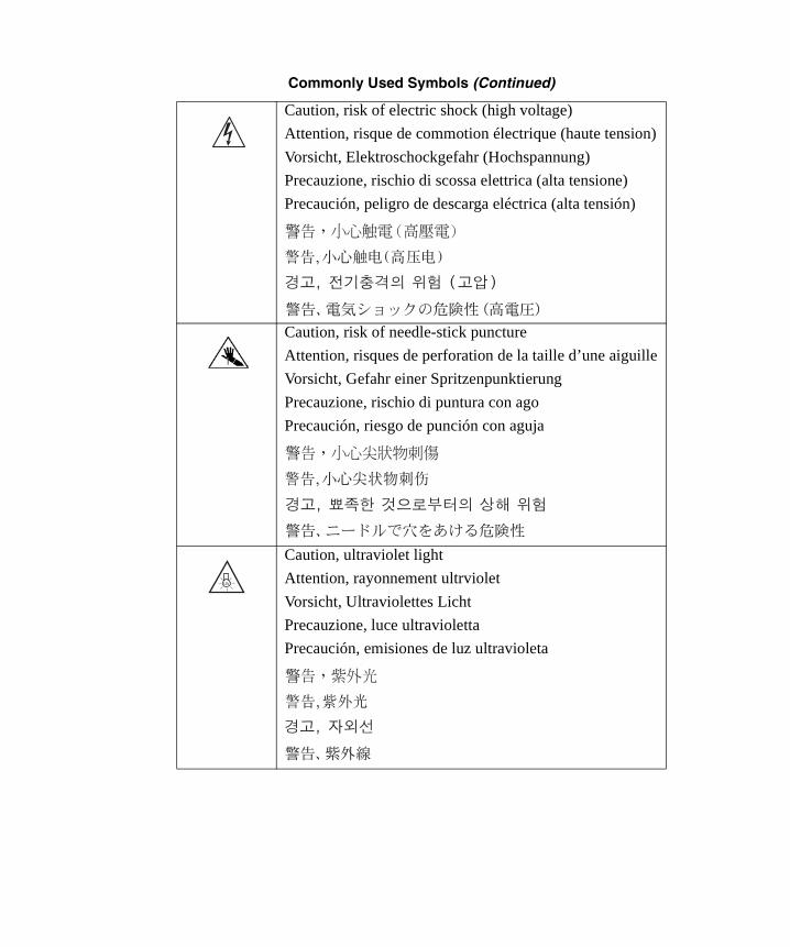
Caution, risk of electric shock (high voltage)
Attention, risque de commotion électrique (haute tension)
Vorsicht, Elektroschockgefahr (Hochspannung)
Precauzione, rischio di scossa elettrica (alta tensione)
Precaución, peligro de descarga eléctrica (alta tensión)
Caution, risk of needle-stick puncture
Attention, risques de perforation de la taille d’une aiguille
Vorsicht, Gefahr einer Spritzenpunktierung
Precauzione, rischio di puntura con ago
Precaución, riesgo de punción con aguja
Caution, ultraviolet light
Attention, rayonnement ultrviolet
Vorsicht, Ultraviolettes Licht
Precauzione, luce ultravioletta
Precaución, emisiones de luz ultravioleta
Commonly Used Symbols (Continued)
UV

2465OG.book Page xiv Wednesday, November 7, 2007 10:33 AM
Fuse
Fusible
Sicherung
Fusibile
Fusible
Electrical power on
Sous tension
Netzschalter ein
Alimentazione elettrica attivata
Alimentación eléctrica conectada
Electrical power off
Hors tension
Netzschalter aus
Alimentazione elettrica disattivata
Alimentación eléctrica desconectada
Commonly Used Symbols (Continued)
1
0

2465OG.book Page xv Wednesday, November 7, 2007 10:33 AM
2465 Electrochemical Detector Information
Intended Use
The Waters® 2465 Electrochemical Detector is designed for HPLC applications.
Biological Hazard
When you analyze physiological fluids, take all necessary precautions and treat all specimens as potentially infectious. Precautions are outlined in “CDC Guidelines on Specimen Handling,” CDC – NIH Manual, 1984.
Calibration
Follow acceptable methods of calibration with pure standards to calibrate methods. Use a minimum of five standards to generate a standard curve. The concentration range should cover the entire range of quality-control samples, typical specimens, and atypical specimens.
Quality Control
Routinely run three quality-control samples. Quality-control samples should represent subnormal, normal, and above-normal levels of a compound. Ensure that quality-control sample results are within an acceptable range, and evaluate precision from day to day and run to run. Data collected when quality-control samples are out of range may not be valid. Do not report this data until you ensure that chromatographic system performance is acceptable.

2465OG.book Page xvi Wednesday, November 7, 2007 10:33 AM
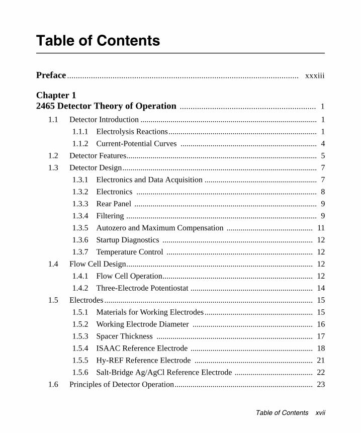
Table of Contents
2465OG.book Page xvii Wednesday, November 7, 2007 10:33 AM
Preface ........................................................................................................... xxxiii
Chapter 1 2465 Detector Theory of Operation ............................................................... 1
1.1 Detector Introduction ........................................................................................ 1
1.1.1 Electrolysis Reactions.......................................................................... 1
1.1.2 Current-Potential Curves .................................................................... 4
1.2 Detector Features............................................................................................... 5
1.3 Detector Design................................................................................................. 7
1.3.1 Electronics and Data Acquisition ........................................................ 7
1.3.2 Electronics .......................................................................................... 8
1.3.3 Rear Panel ........................................................................................... 9
1.3.4 Filtering ............................................................................................... 9
1.3.5 Autozero and Maximum Compensation ........................................... 11
1.3.6 Startup Diagnostics ........................................................................... 12
1.3.7 Temperature Control ......................................................................... 12
1.4 Flow Cell Design............................................................................................. 12
1.4.1 Flow Cell Operation........................................................................... 12
1.4.2 Three-Electrode Potentiostat ............................................................. 14
1.5 Electrodes ........................................................................................................ 15
1.5.1 Materials for Working Electrodes ...................................................... 15
1.5.2 Working Electrode Diameter ............................................................ 16
1.5.3 Spacer Thickness .............................................................................. 17
1.5.4 ISAAC Reference Electrode ............................................................. 18
1.5.5 Hy-REF Reference Electrode ........................................................... 21
1.5.6 Salt-Bridge Ag/AgCl Reference Electrode ....................................... 22
1.6 Principles of Detector Operation..................................................................... 23
Table of Contents xvii

2465OG.book Page xviii Wednesday, November 7, 2007 10:33 AM
1.6.1 DC Mode............................................................................................ 23
1.6.2 Pulse (PAD) Mode ............................................................................ 24
1.6.3 Scan Mode ........................................................................................ 32
1.7 References ....................................................................................................... 33
Chapter 2 Installing the 2465 Detector ........................................................................... 35
2.1 Site Selection and Power Requirements.......................................................... 35
2.1.1 Site Selection ..................................................................................... 35
2.1.2 Power Requirements ......................................................................... 37
2.2 Unpacking and Inspecting the 2465 Detector ................................................. 38
2.3 Making Electrical Power Connections ............................................................ 39
2.4 Making Fluidic Connections ........................................................................... 40
2.4.1 Installing the 2465 Detector............................................................... 43
2.4.2 Connecting a Column ....................................................................... 46
2.4.3 Installing the Flow Cell ..................................................................... 47
2.5 Making I/O Signal Connections ...................................................................... 51
2.5.1 Rear Panel Connections ..................................................................... 51
2.5.2 Connecting to a 2695 Separations Module (Stand-Alone) ............... 55
2.5.3 Connecting to a busSAT/IN Module ................................................. 57
2.5.4 Connecting to a 746 Data Module .................................................... 59
2.5.5 Making RS-232 Connections ............................................................ 60
2.6 Verifying COM Port Settings .......................................................................... 61
Chapter 3 Operating the 2465 Detector ......................................................................... 63
3.1 Starting Up the Detector.................................................................................. 63
3.1.1 Powering On the Detector.................................................................. 63
3.1.2 Using the Display .............................................................................. 64
3.1.3 Using the Keypad .............................................................................. 65
3.1.4 Finding the Parameters ..................................................................... 66
xviii Table of Contents

2465OG.book Page xix Wednesday, November 7, 2007 10:33 AM
3.1.5 Using the Function Keys ................................................................... 66
3.1.6 Using the Keypad to Change Parameters ......................................... 67
3.1.7 Function Key Commands ................................................................. 67
3.1.8 Status and Control Parameters .......................................................... 70
3.2 Overview of the 2465 Detector Modes ........................................................... 74
3.2.1 DC Mode............................................................................................ 75
3.2.2 Pulse (PAD) Mode ............................................................................ 77
3.2.3 Scan Mode ........................................................................................ 79
3.2.4 Remote Mode .................................................................................... 79
3.2.5 Introduction to Time Files ................................................................. 81
3.2.6 Programming Output Event Functions in Time Files ....................... 84
3.3 Preparing the 2465 Detector for Operation ..................................................... 85
3.3.1 Preparing the Detector for Remote Control from Empower.............. 87
3.3.2 Changing from Remote Mode to Stand-Alone Mode ....................... 89
3.3.3 Equilibrating the Detector ................................................................. 89
3.4 Using DC Mode .............................................................................................. 91
3.4.1 Setting Initial Conditions in DC Mode .............................................. 92
3.4.2 Turning the Flow Cell On and Off in DC Mode ............................... 94
3.4.3 Creating a Time File in DC Mode .................................................... 96
3.4.4 Running a Time File in DC Mode .................................................. 101
3.5 Using Pulse (PAD) Mode .............................................................................. 103
3.5.1 Setting Initial Conditions in Pulse Mode......................................... 104
3.5.2 Changing the Range in Pulse Mode ................................................ 106
3.5.3 Making a Chart Mark in Pulse Mode .............................................. 107
3.5.4 Autozeroing the Detector in Pulse Mode ........................................ 107
3.5.5 Turning the Flow Cell On and Off in Pulse Mode .......................... 107
3.5.6 Creating a Time File in Pulse Mode ............................................... 109
3.5.7 Running a Time File in Pulse Mode ............................................... 115
3.6 Using Scan Mode .......................................................................................... 116
3.6.1 Setting Initial Conditions in Scan Mode.......................................... 116
Table of Contents xix
2465OG.book Page xx Wednesday, November 7, 2007 10:33 AM
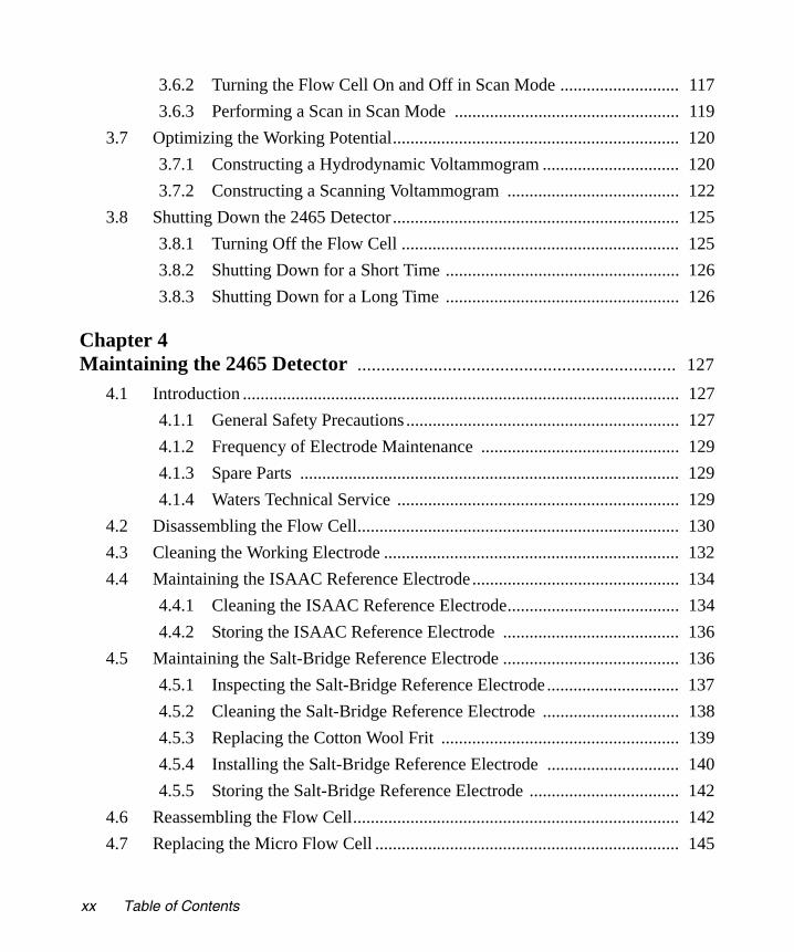
3.6.2 Turning the Flow Cell On and Off in Scan Mode ........................... 117
3.6.3 Performing a Scan in Scan Mode ................................................... 119
3.7 Optimizing the Working Potential................................................................. 120
3.7.1 Constructing a Hydrodynamic Voltammogram ............................... 120
3.7.2 Constructing a Scanning Voltammogram ....................................... 122
3.8 Shutting Down the 2465 Detector ................................................................. 125
3.8.1 Turning Off the Flow Cell ............................................................... 125
3.8.2 Shutting Down for a Short Time ..................................................... 126
3.8.3 Shutting Down for a Long Time ..................................................... 126
Chapter 4 Maintaining the 2465 Detector ................................................................... 127
4.1 Introduction ................................................................................................... 127
4.1.1 General Safety Precautions .............................................................. 127
4.1.2 Frequency of Electrode Maintenance ............................................. 129
4.1.3 Spare Parts ...................................................................................... 129
4.1.4 Waters Technical Service ................................................................ 129
4.2 Disassembling the Flow Cell......................................................................... 130
4.3 Cleaning the Working Electrode ................................................................... 132
4.4 Maintaining the ISAAC Reference Electrode ............................................... 134
4.4.1 Cleaning the ISAAC Reference Electrode....................................... 134
4.4.2 Storing the ISAAC Reference Electrode ........................................ 136
4.5 Maintaining the Salt-Bridge Reference Electrode ........................................ 136
4.5.1 Inspecting the Salt-Bridge Reference Electrode .............................. 137
4.5.2 Cleaning the Salt-Bridge Reference Electrode ............................... 138
4.5.3 Replacing the Cotton Wool Frit ...................................................... 139
4.5.4 Installing the Salt-Bridge Reference Electrode .............................. 140
4.5.5 Storing the Salt-Bridge Reference Electrode .................................. 142
4.6 Reassembling the Flow Cell.......................................................................... 142
4.7 Replacing the Micro Flow Cell ..................................................................... 145
xx Table of Contents

2465OG.book Page xxi Wednesday, November 7, 2007 10:33 AM
4.8 Other Procedures ........................................................................................... 147
4.8.1 Replacing Fuses ............................................................................... 147
4.8.2 Changing a Spacer in the Flow Cell ............................................... 149
4.8.3 Changing a Column ........................................................................ 150
4.8.4 Cleaning the Detector ..................................................................... 150
Chapter 5 Diagnostics and Troubleshooting ............................................................... 151
5.1 Error Messages .............................................................................................. 152
5.2 Diagnostics .................................................................................................... 152
5.2.1 Dummy Cell Test ............................................................................. 152
5.2.2 Stop Flow Test ................................................................................ 155
5.2.3 Keyboard Test ................................................................................. 156
5.2.4 Display Test .................................................................................... 156
5.3 Troubleshooting Tables ................................................................................. 157
5.4 Physical Symptoms ....................................................................................... 161
Appendix A 2465 Detector Specifications ........................................................................ 163
Appendix B 2465 Detector Components and Spare Parts ........................................... 167
B.1 Flow Cells ............................................................................................ 167
B.2 Startup Kit Components ........................................................................ 172
B.3 Spare Parts ............................................................................................ 173
Table of Contents xxi

2465OG.book Page xxii Wednesday, November 7, 2007 10:33 AM
Appendix C Sample ECD Methods ................................................................................... 175
Appendix D 2465 Detector Glossary ................................................................................. 179
Index ................................................................................................................. 183
xxii Table of Contents
List of Figures
2465OG.book Page xxiii Wednesday, November 7, 2007 10:33 AM
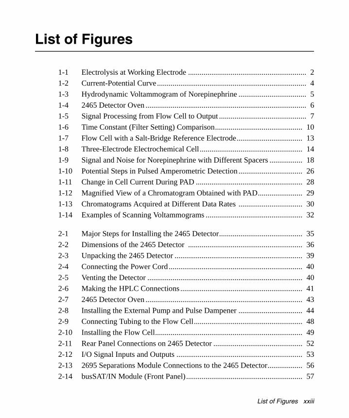
1-1 Electrolysis at Working Electrode ............................................................. 2
1-2 Current-Potential Curve ............................................................................. 4
1-3 Hydrodynamic Voltammogram of Norepinephrine ................................... 5
1-4 2465 Detector Oven ................................................................................... 6
1-5 Signal Processing from Flow Cell to Output ............................................. 7
1-6 Time Constant (Filter Setting) Comparison............................................. 10
1-7 Flow Cell with a Salt-Bridge Reference Electrode.................................. 13
1-8 Three-Electrode Electrochemical Cell ..................................................... 14
1-9 Signal and Noise for Norepinephrine with Different Spacers ................. 18
1-10 Potential Steps in Pulsed Amperometric Detection ................................. 26
1-11 Change in Cell Current During PAD ....................................................... 28
1-12 Magnified View of a Chromatogram Obtained with PAD....................... 29
1-13 Chromatograms Acquired at Different Data Rates ................................. 30
1-14 Examples of Scanning Voltammograms .................................................. 32
2-1 Major Steps for Installing the 2465 Detector........................................... 35
2-2 Dimensions of the 2465 Detector ........................................................... 36
2-3 Unpacking the 2465 Detector .................................................................. 39
2-4 Connecting the Power Cord ..................................................................... 40
2-5 Venting the Detector ................................................................................ 40
2-6 Making the HPLC Connections ............................................................... 41
2-7 2465 Detector Oven ................................................................................. 43
2-8 Installing the External Pump and Pulse Dampener ................................. 44
2-9 Connecting Tubing to the Flow Cell........................................................ 48
2-10 Installing the Flow Cell............................................................................ 49
2-11 Rear Panel Connections on 2465 Detector .............................................. 52
2-12 I/O Signal Inputs and Outputs ................................................................. 53
2-13 2695 Separations Module Connections to the 2465 Detector.................. 56
2-14 busSAT/IN Module (Front Panel)............................................................ 57
List of Figures xxiii

2465OG.book Page xxiv Wednesday, November 7, 2007 10:33 AM
2-15 Connecting a busSAT/IN Module Channel 1 to the 2465 Detector......... 58
2-16 Config Screen .......................................................................................... 59
2-17 IEEE-488 and RS-232 Connections in a Waters Empower System ........ 61
3-1 Calculating Checksum Screen ................................................................. 64
3-2 Checksum Screen..................................................................................... 64
3-3 Main Screen ............................................................................................. 64
3-4 2465 Detector Display and Keypad ......................................................... 65
3-5 DC Mode Navigation............................................................................... 75
3-6 Pulse Mode Navigation............................................................................ 77
3-7 Scan Mode Navigation............................................................................. 79
3-8 Remote DC Mode .................................................................................... 80
3-9 Remote Pulse Mode ................................................................................. 80
3-10 Remote Scan Mode.................................................................................. 80
3-11 Run (Waiting) Screen Before Starting a Run........................................... 83
3-12 Run Screen After Starting a Run ............................................................. 83
3-13 End Cycle Time Screen for an Empty Time File ..................................... 84
3-14 Acquisition Server Dialog Box................................................................ 88
3-15 DC Setup Screen ...................................................................................... 89
3-16 Derating Curve for Detector Oven Temperature ..................................... 90
3-17 DC Stat Screen......................................................................................... 90
3-18 DC Setup Screen ...................................................................................... 92
3-19 Change Polarity to Negative Screen ........................................................ 93
3-20 Change Polarity to Positive Screen.......................................................... 93
3-21 DC Stat Screen......................................................................................... 93
3-22 DC Stat Screen with Cell Off................................................................... 95
3-23 Switch Cell On Screen ............................................................................. 95
3-24 Switch Cell Off Screen ............................................................................ 95
3-25 DC Setup Screen ...................................................................................... 96
3-26 Events Setup Screen................................................................................. 97
3-27 Prog Screen with Initial Conditions......................................................... 97
3-28 Delete Timefile Screen............................................................................. 98
xxiv List of Figures

2465OG.book Page xxv Wednesday, November 7, 2007 10:33 AM
3-29 Overwrite Time Screen ............................................................................ 98
3-30 Prog Screen After Changing Line 1......................................................... 99
3-31 Prog Screen After Changing Cell Potential ............................................. 99
3-32 Prog Screen After Adding Line 2 ............................................................ 99
3-33 Prog Screen After Adding Line 3 .......................................................... 100
3-34 End Cycle Time Screen.......................................................................... 100
3-35 Events Setup Screen with Time File 2 ................................................... 101
3-36 Run (Waiting) Screen............................................................................. 102
3-37 Run Screen After Starting a Run ........................................................... 102
3-38 Pulse Setup1 Screen............................................................................... 104
3-39 Pulse Setup2 Screen............................................................................... 104
3-40 Change Polarity to Negative Screen ...................................................... 105
3-41 Pulse Stat Screen when Flow Cell Is On ............................................... 105
3-42 Pulse Stat Screen when Flow Cell Is Off ............................................... 106
3-43 Pulse Stat Screen with Cell Off.............................................................. 108
3-44 Switch Cell On Screen ........................................................................... 108
3-45 Switch Cell Off Screen .......................................................................... 109
3-46 Pulse Setup1 Screen............................................................................... 110
3-47 Pulse Setup2 Screen............................................................................... 110
3-48 Events Setup Screen............................................................................... 110
3-49 Prog Screen with Initial Conditions....................................................... 111
3-50 Delete Timefile Screen........................................................................... 111
3-51 Overwrite Time Screen .......................................................................... 112
3-52 Prog Screen After Changing Line 1....................................................... 112
3-53 Prog Screen After Adding Line 2 .......................................................... 113
3-54 Prog Screen After Adding Line 3 .......................................................... 113
3-55 End Cycle Time Screen.......................................................................... 114
3-56 Events Setup Screen with Time File 2 ................................................... 114
3-57 Run (Waiting) Screen............................................................................. 115
3-58 Run Screen After Starting a Run ........................................................... 115
3-59 Scan Setup Screen.................................................................................. 116
3-60 Scan Stat Screen..................................................................................... 117
List of Figures xxv
2465OG.book Page xxvi Wednesday, November 7, 2007 10:33 AM
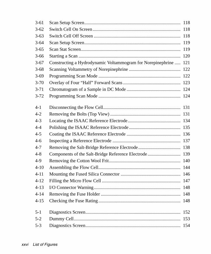
3-61 Scan Setup Screen.................................................................................. 118
3-62 Switch Cell On Screen ........................................................................... 118
3-63 Switch Cell Off Screen .......................................................................... 118
3-64 Scan Setup Screen.................................................................................. 119
3-65 Scan Stat Screen..................................................................................... 119
3-66 Starting a Scan ....................................................................................... 120
3-67 Constructing a Hydrodynamic Voltammogram for Norepinephrine ..... 121
3-68 Scanning Voltammetry of Norepinephrine ............................................ 122
3-69 Programming Scan Mode ...................................................................... 122
3-70 Overlay of Four “Half” Forward Scans ................................................. 123
3-71 Chromatogram of a Sample in DC Mode .............................................. 124
3-72 Programming Scan Mode ...................................................................... 124
4-1 Disconnecting the Flow Cell.................................................................. 131
4-2 Removing the Bolts (Top View) ............................................................ 131
4-3 Locating the ISAAC Reference Electrode............................................. 134
4-4 Polishing the ISAAC Reference Electrode ............................................ 135
4-5 Coating the ISAAC Reference Electrode .............................................. 136
4-6 Inspecting a Reference Electrode .......................................................... 137
4-7 Removing the Salt-Bridge Reference Electrode .................................... 138
4-8 Components of the Salt-Bridge Reference Electrode ............................ 139
4-9 Removing the Cotton Wool Frit............................................................. 140
4-10 Assembling the Flow Cell...................................................................... 144
4-11 Mounting the Fused Silica Connector ................................................... 146
4-12 Filling the Micro Flow Cell ................................................................... 147
4-13 I/O Connector Warning.......................................................................... 148
4-14 Removing the Fuse Holder .................................................................... 148
4-15 Checking the Fuse Rating ...................................................................... 148
5-1 Diagnostics Screen................................................................................. 152
5-2 Dummy Cell........................................................................................... 153
5-3 Diagnostics Screen................................................................................. 154
xxvi List of Figures

2465OG.book Page xxvii Wednesday, November 7, 2007 10:33 AM
5-4 Noise Test with Dummy Cell................................................................. 154
5-5 Noise Test Screen................................................................................... 155
5-6 Testing a Key on the Keypad ................................................................. 156
5-7 Display Test ........................................................................................... 157
5-8 Configuration Screen ............................................................................. 157
List of Figures xxvii

2465OG.book Page xxviii Wednesday, November 7, 2007 10:33 AM
xxviii List of Figures
List of Tables
2465OG.book Page xxix Wednesday, November 7, 2007 10:33 AM
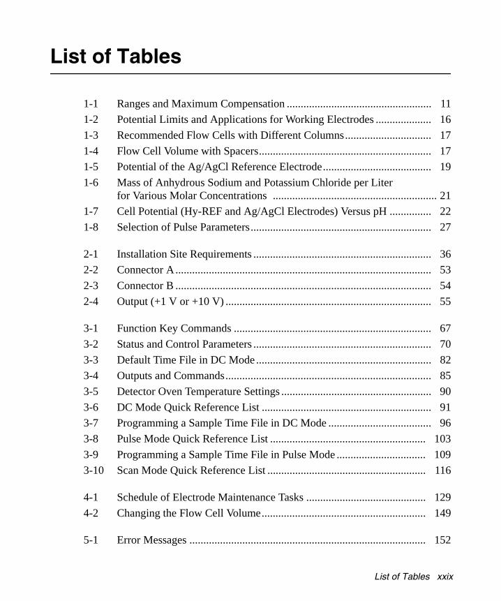
1-1 Ranges and Maximum Compensation .................................................... 11
1-2 Potential Limits and Applications for Working Electrodes .................... 16
1-3 Recommended Flow Cells with Different Columns............................... 17
1-4 Flow Cell Volume with Spacers.............................................................. 17
1-5 Potential of the Ag/AgCl Reference Electrode....................................... 19
1-6 Mass of Anhydrous Sodium and Potassium Chloride per Liter for Various Molar Concentrations ........................................................... 21
1-7 Cell Potential (Hy-REF and Ag/AgCl Electrodes) Versus pH ............... 22
1-8 Selection of Pulse Parameters................................................................. 27
2-1 Installation Site Requirements ................................................................ 36
2-2 Connector A............................................................................................ 53
2-3 Connector B ............................................................................................ 54
2-4 Output (+1 V or +10 V) .......................................................................... 55
3-1 Function Key Commands ....................................................................... 67
3-2 Status and Control Parameters ................................................................ 70
3-3 Default Time File in DC Mode ............................................................... 82
3-4 Outputs and Commands.......................................................................... 85
3-5 Detector Oven Temperature Settings ...................................................... 90
3-6 DC Mode Quick Reference List ............................................................. 91
3-7 Programming a Sample Time File in DC Mode ..................................... 96
3-8 Pulse Mode Quick Reference List ........................................................ 103
3-9 Programming a Sample Time File in Pulse Mode ................................ 109
3-10 Scan Mode Quick Reference List ......................................................... 116
4-1 Schedule of Electrode Maintenance Tasks ........................................... 129
4-2 Changing the Flow Cell Volume........................................................... 149
5-1 Error Messages ..................................................................................... 152
List of Tables xxix

2465OG.book Page xxx Wednesday, November 7, 2007 10:33 AM
5-2 Dummy Cell Test Settings .................................................................... 154
5-3 No Detector Response .......................................................................... 158
5-4 High Cell Current.................................................................................. 158
5-5 Noisy Baseline ...................................................................................... 159
5-6 Drifting Baseline................................................................................... 159
5-7 Decreased Sensitivity (Low S/N Ratio)................................................ 160
5-8 Baseline Oscillations............................................................................. 160
5-9 Saturation of Output.............................................................................. 160
5-10 Physical Symptoms............................................................................... 161
A-1 General Specifications .......................................................................... 163
A-2 Physical Specifications ......................................................................... 164
A-3 Operating and Environmental Requirements........................................ 164
A-4 DC Mode............................................................................................... 164
A-5 Pulse Mode ........................................................................................... 165
A-6 Scan Mode ............................................................................................ 165
A-7 Timed Events Mode .............................................................................. 165
A-8 Flow Cell Specifications ....................................................................... 165
B-1 Flow Cell Kits ....................................................................................... 167
B-2 Flow Cell, 2-mm GC WE, Salt-Bridge Reference Electrode ............... 168
B-3 Flow Cell, 2-mm GC WE, ISAAC Reference Electrode...................... 169
B-4 Flow Cell, 3-mm Pt WE, ISAAC Reference Electrode ........................ 169
B-5 Flow Cell, 3-mm Au WE, Hy-REF Electrode ...................................... 170
B-6 Flow Cell, 2-mm Ag WE, Hy-REF Electrode ...................................... 170
B-7 Micro Flow Cell, 0.7-mm GC WE, Salt-Bridge REF Electrode .......... 171
B-8 Startup Kit ............................................................................................. 172
B-9 Spare Parts ............................................................................................ 173
C-1 Norepinephrine ..................................................................................... 175
C-2 Catecholamines ..................................................................................... 175
C-3 Homocysteine ....................................................................................... 176
xxx List of Tables

2465OG.book Page xxxi Wednesday, November 7, 2007 10:33 AM
C-4 8-Hydroxy-2’-deoxyguanosine ............................................................. 177
C-5 Lactose, Sucrose, and Maltose.............................................................. 177
C-6 Performance Qualification .................................................................... 178
List of Tables xxxi

2465OG.book Page xxxii Wednesday, November 7, 2007 10:33 AM
xxxii List of Tables

2465OG.book Page xxxiii Wednesday, November 7, 2007 10:33 AM
Preface
The Waters 2465 Electrochemical Detector Operator’s Guide describes the procedures for unpacking, installing, operating, verifying, maintaining, and troubleshooting the Waters® 2465 Electrochemical Detector (ECD). It also includes appendixes containing instrument specifications, spare parts, and a glossary.
Anyone who installs, maintains, operates, or troubleshoots the Waters 2465 Electrochemical Detector can use this guide. All personnel who use this guide should be familiar with HPLC terms and practices and be capable of performing basic HPLC system operations such as making fluidic connections.
Organization
This guide contains the following:
Chapter 1 summarizes the features of the 2465 Detector and describes the theory and principles of operation.
Chapter 2 describes how to install the 2465 Detector, make power, fluidic, and signal connections, and connect the detector to other devices.
Chapter 3 describes how to set up and operate the 2465 Detector in remote and stand-alone modes.
Chapter 4 describes how to clean and replace various parts of the 2465 Detector.
Chapter 5 describes the error messages, diagnostics, and recommended actions to solve problems with the 2465 Detector.
Appendix A contains operational, environmental, optical, and voltage specifications for the 2465 Detector.
Appendix B lists recommended and optional spare parts for the 2465 Detector.
Appendix C provides sample methods and application notes for the 2465 Detector.
Appendix D provides a glossary of terms for the 2465 Detector.
Related Documentation
Waters Licenses, Warranties, and Support: Provides software license and warranty information, describes training and extended support, and tells how Waters handles shipments, damages, claims, and returns.
xxxiii

2465OG.book Page xxxiv Wednesday, November 7, 2007 10:33 AM
Online Documentation
Empower Help: Describes all Empower windows, menus, menu selections, and dialog boxes for the base software and software options. Also includes reference information and procedures for performing all tasks required to use Empower software. Included as part of the Empower software.
Printed Documentation
Waters Bus SAT/IN Module Installation Guide: Describes installation of the Waters Bus SAT/IN™ Module.
Millennium32 System Installation and Configuration Guide: Describes Millennium32 software installation. Discusses how to configure the computer and chromatographic instruments as part of the Millennium32 System. Also covers the installation, configuration, and use of acquisition servers such as the LAC/E32 module, the busLAC/E™ card, and interface cards used to communicate with serial instruments.
Empower System Installation and Configuration Guide: Describes Empower software installation, including the stand-alone Personal workstation, Workgroup configuration, and the Enterprise client/server system. Discusses how to configure the computer and chromatographic instruments as part of the Empower System. Also covers the installation, configuration, and use of acquisition servers such as the LAC/E32 module, the busLAC/E card, and interface cards used to communicate with serial instruments.
Documentation Conventions
The following conventions can be used in this guide:
Convention Usage
Bold Bold indicates user action such as keys to press, menu selections, and commands. For example, “Click Next to go to the next page.”
Italic Italic indicates information that you supply such as variables. It also indicates emphasis and document titles. For example, “Replace file_name with the actual name of your file.”
Courier Courier indicates examples of source code and system output. For example, “The SVRMGR> prompt appears.”
Courier Bold Courier bold indicates characters that you type or keys you press in examples of source code. For example, “At the LSNRCTL> prompt, enter set password oracle to access Oracle.”
xxxiv

2465OG.book Page xxxv Wednesday, November 7, 2007 10:33 AM
Notes
Notes call out information that is helpful to the operator. For example:
Note: Record your result before you proceed to the next step.
Attentions
Attentions provide information about preventing damage to the system or equipment. For example:
Cautions
Cautions provide information essential to the safety of the operator. For example:
Keys The word key refers to a computer key on the keypad or keyboard. Screen keys refer to the keys on the instrument located immediately below the screen. For example, “The A/B screen key on the 2414 Detector displays the selected channel.”
… Three periods indicate that more of the same type of item can optionally follow. For example, “You can store filename1, filename2, … in each folder.”
> A right arrow between menu options indicates you should choose each option in sequence. For example, “Select File > Exit” means you should select File from the menu bar, then select Exit from the File menu.
Attention: Never lift the 2465 Detector by the door at the front, but only by its sides, or you may damage the detector.
Caution: To avoid burns, turn off the lamp at least 30 minutes before removing it for replacement or adjustment.
Caution: To avoid electrical shock and injury, turn off the detector and unplug the power cord before performing maintenance procedures.
Caution: To avoid chemical or electrical hazards, observe safe laboratory practices when operating the system.
Convention Usage
xxxv

2465OG.book Page xxxvi Wednesday, November 7, 2007 10:33 AM
xxxvi

1
2465OG.book Page 1 Wednesday, November 7, 2007 10:33 AM
Chapter 1 2465 Detector Theory of Operation
This chapter introduces the Waters® 2465 Electrochemical Detector (2465 Detector). It summarizes the 2465 Detector’s features and major components, and describes the theory and principles of operation. To use the detector effectively, you should understand its principles of operation and design.
1.1 Detector Introduction
Electrochemical detection theory involves the understanding of:
• Electrolysis reactions
• Current-potential curves
The 2465 Detector is amperometric, because the detector’s response is measured in amperes, or current. Coulometry measures the quantity of charge and computes the absolute mass of analyte from Faraday’s law:
Q = n × F × N
where:
Q = Mass of analyte
n = Number of moles (M) of electrons lost or gained
F = Faraday’s constant (96,500 coulombs/mole of electrons)
N = Number of moles of analyte
1.1.1 Electrolysis Reactions
Electrochemical detection differs from other detection methods in that the analyte undergoes an electrochemical reaction while being detected (Figure 1-1). Upon elution from the column, the analyte passes through the electrochemical cell, where it undergoes either oxidation or reduction at the working electrode (WE). The controller (potentiostat)
Detector Introduction 1

1
2465OG.book Page 2 Wednesday, November 7, 2007 10:33 AM
maintains the potential of the working electrode (relative to a reference electrode) at a value that causes the analyte to electrolyze. It simultaneously measures the electrolysis current resulting from the oxidation (or reduction) of the analyte.
Figure 1-1 Electrolysis at Working Electrode
An electrical current is the rate of electricity flow. It is also a measure of the rate of the reaction taking place at the working electrode. The more positive the working electrode potential, the more strongly it can oxidize passing species.
In order for a molecule in solution to undergo an oxidation or reduction at an electrode, it must complete a three-step process: diffusion to the electrode surface, oxidation or reduction, then diffusion away from the vicinity of the working electrode (to allow acceptance or release of electrons from another molecule). The details of the process are as follows:
1. Mass transport of the analyte from the bulk of solution to the electrode surface
Even in rapid LC flow rates, there is a stagnant layer of fluid at the electrode surface through which diffusion is the mode of mass transport. Diffusion in liquids at room temperature is relatively slow. Typical liquid phase diffusion coefficients are 1 to 10 × 10–6 cm/sec2. Small molecule diffusion rates do not differ widely for molecular weights around 100. Therefore, the flow rate, geometry of the flow cell, diffusion coefficient, and viscosity of the fluid are in effect the primary factors that determine the rate of mass transport.
2. Electron transfer at the electrode surface
The rate of this step is determined primarily by the applied potential. Generally, the potential selected is high so that this step is very rapid relative to the rate of mass transport. The Nernst equation describes this behavior:
E = E0 + (RT/nF) ln [Ox]/[Red]
Ox + ne–
Red
Red
Ox
Mass Transport to Solution
Working Electrode Surface
2 2465 Detector Theory of Operation

1
2465OG.book Page 3 Wednesday, November 7, 2007 10:33 AM
where [Ox] and [Red] are the surface concentrations of the oxidized and reduced forms of the analyte, or:
∆E = (E – E0) = RT/nF ln [Ox]/[Red]
where:
E = Potential
E0 = Standard potential of the analyte
R = Gas constant
T = Temperature
n = Number of electrons
[Ox] = Concentration of oxidized form
[Red] = Concentration of reduced form
If ∆E is greater than zero, the concentration of the oxidized form is greater and oxidation results. If ∆E is less than zero, the concentration of the reduced form is greater and reduction results.
3. Mass transport of the electrolytic product(s) from the electrode surface
In any multiple-stage process, the slowest or the rate-limiting step determines the overall rate. Because the oxidized or reduced forms of a molecule have to reach the electrode surface, the growth of the current is limited by the rate of mass transport. There are generally three modes of mass transport: convection, migration, and diffusion. Diffusion is the slowest. Thus mass transport is a diffusion-limited step. The limiting current in a flow cell, when ∆E is large, is given by the following equation, which defines a linear relationship:
where:
i = Mass transport limited current in a given flow cell
n = Number of electrons transferred
F = Faraday’s constant
A = Electrode area
D = Diffusion coefficient
δ = Diffusion layer thickness
C = Concentration of the analyte in the flow cell
iLIMITING nFAD
δ---- C=
Detector Introduction 3

1
2465OG.book Page 4 Wednesday, November 7, 2007 10:33 AM
Therefore, when the flow rate is constant, the diffusion layer thickness is constant, and the current is proportional to the concentration of the analyte. As with any concentration-dependent detector in which the column efficiency and capacity factor are constant, the peak height is directly proportional to the mass injected on the column.
1.1.2 Current-Potential CurvesThe selection of the appropriate applied potential should be based upon an understanding of the current-potential curve(s) of the analyte(s). The current-potential curve should be obtained under the conditions identical to the mobile phase used for the analysis. A current-potential curve for a flowing solution at constant flow rate is called a hydrodynamic voltammogram. Figure 1-2 shows an idealized hydrodynamic voltammogram for an oxidation.
Figure 1-2 Current-Potential Curve
The significant characteristics of a current-potential curve are the E1/2 and the limiting current plateau. The E1/2 is very nearly equal to the standard reduction potential of the analyte. The limiting current plateau corresponds to those potentials that result in nearly instantaneous electrolysis of the analyte upon reaching the electrode surface. In general, select the smallest potential at the plateau that can oxidize all peaks of interest. Operating at greater potential does not increase the signal and is likely to increase noise.
Reduction Current
Reduction of Mobile Phase
Applied Potential
( + )
Mobile Phase Without Analyte
Mobile Phase With Analyte
Oxidation of Mobile Phase
Oxidation Current
( – )
E1/2
4 2465 Detector Theory of Operation
1
2465OG.book Page 5 Wednesday, November 7, 2007 10:33 AM
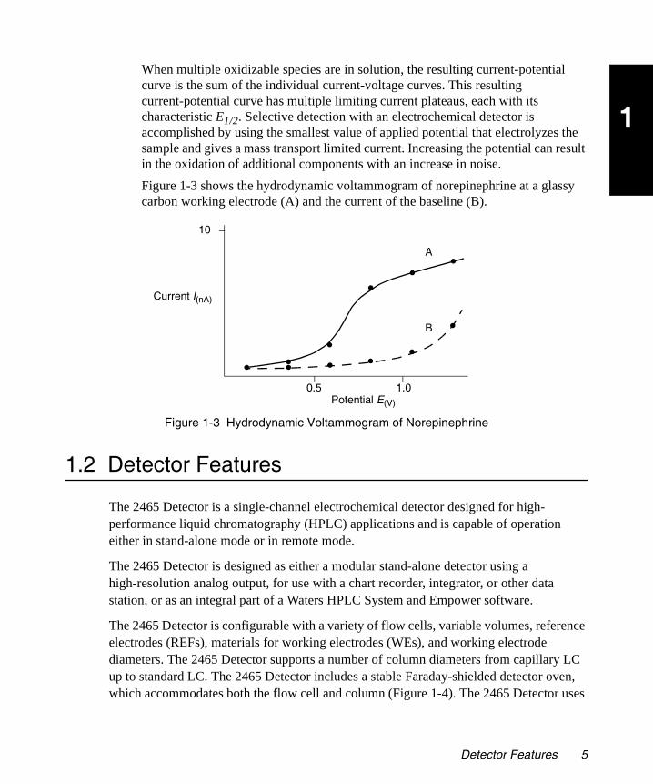
When multiple oxidizable species are in solution, the resulting current-potential curve is the sum of the individual current-voltage curves. This resulting current-potential curve has multiple limiting current plateaus, each with its characteristic E1/2. Selective detection with an electrochemical detector is accomplished by using the smallest value of applied potential that electrolyzes the sample and gives a mass transport limited current. Increasing the potential can result in the oxidation of additional components with an increase in noise.
Figure 1-3 shows the hydrodynamic voltammogram of norepinephrine at a glassy carbon working electrode (A) and the current of the baseline (B).
Figure 1-3 Hydrodynamic Voltammogram of Norepinephrine
1.2 Detector Features
The 2465 Detector is a single-channel electrochemical detector designed for high- performance liquid chromatography (HPLC) applications and is capable of operation either in stand-alone mode or in remote mode.
The 2465 Detector is designed as either a modular stand-alone detector using a high-resolution analog output, for use with a chart recorder, integrator, or other data station, or as an integral part of a Waters HPLC System and Empower software.
The 2465 Detector is configurable with a variety of flow cells, variable volumes, reference electrodes (REFs), materials for working electrodes (WEs), and working electrode diameters. The 2465 Detector supports a number of column diameters from capillary LC up to standard LC. The 2465 Detector includes a stable Faraday-shielded detector oven, which accommodates both the flow cell and column (Figure 1-4). The 2465 Detector uses
A
B
10
Current I(nA)
0.5 1.0Potential E(V)
Detector Features 5
1
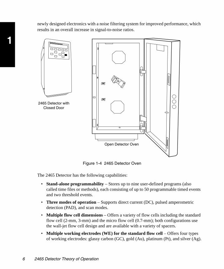
2465OG.book Page 6 Wednesday, November 7, 2007 10:33 AM
newly designed electronics with a noise filtering system for improved performance, which results in an overall increase in signal-to-noise ratios.
Figure 1-4 2465 Detector Oven
The 2465 Detector has the following capabilities:
• Stand-alone programmability – Stores up to nine user-defined programs (also called time files or methods), each consisting of up to 50 programmable timed events and two threshold events.
• Three modes of operation – Supports direct current (DC), pulsed amperometric detection (PAD), and scan modes.
• Multiple flow cell dimensions – Offers a variety of flow cells including the standard flow cell (2-mm, 3-mm) and the micro flow cell (0.7-mm); both configurations use the wall-jet flow cell design and are available with a variety of spacers.
• Multiple working electrodes (WE) for the standard flow cell – Offers four types of working electrodes: glassy carbon (GC), gold (Au), platinum (Pt), and silver (Ag).
Open Detector Oven
2465 Detector with Closed Door
6 2465 Detector Theory of Operation

1
2465OG.book Page 7 Wednesday, November 7, 2007 10:33 AM
• Multiple reference electrodes (REF) for the standard flow cell – Offers three reference electrodes: salt-bridge silver/silver chloride (sb REF), in-situ silver/silver chloride (ISAAC), and hydrogen reference (Hy-REF).
• Dummy cell – Facilitates troubleshooting by enabling you to isolate and test the electronics and control without the variability introduced by the presence of a real flow cell.
• Detector oven (column and flow cell heater compartment) – Faraday-shielded oven; provides thermal operating stability and reduces noise and drift characteristics.
• Method editing and storage – Supports basic method programming, storage, and retrieval from the front panel.
• Diagnostic capability – Supports built-in diagnostic tools to optimize functionality and performance.
• Rear panel I/O connectors – Include main power, chassis ground connector, two contact closure outputs, two relays, six external event inputs, and an RS-232C connector for full instrument control (optional).
1.3 Detector Design
1.3.1 Electronics and Data Acquisition
In the electrochemical flow cell, the electron transfer takes place at the working electrode during an oxidation or reduction reaction. The resulting electrical current is amplified by the current-potential (I/E) converter (Figure 1-5).
Figure 1-5 Signal Processing from Flow Cell to Output
The signal or current from the I/E converter can be compensated with autozero or offset, and is digitized using a 24-bit ADC (analog-to-digital converter). The signal is processed
Flow Cell I/E Converter 24-Bit ADC CPU 20-Bit DAC
Autozero / Offset Compensation
Output1-V or
10-V Full Scale
OutputRS-232
Detector Design 7

1
2465OG.book Page 8 Wednesday, November 7, 2007 10:33 AM
in the CPU using noise filtering or more complex data processing in PAD. Finally the signal is sent:
• Through a 20-bit DAC (digital-to-analog converter), then as a 1- or 10-V full scale output (which you can select from the Configuration menu)
• As an RS-232 output
1.3.2 Electronics
I/E Converter
The I/E converter selects the resistor appropriate to the current range at the selected applied cell potential.
Sensor Board
Description
The sensor board receives inputs from the flow cell. The current is digitized and any offset settings and compensation are applied for the range selected. The processor receives this modified signal and passes it on to the flash memory and other circuitry. The sensor board reacts to the state of various signals on the DB-25 connector on the back of the unit, and passes signal information on to the control board. The sensor board generates an analog 1- to 10-V output on the BNC connector analogous to the input signal received from the flow cell.
Interconnections
The sensor board has two connectors that extend through the back of the unit. One is a 15-pin connector for event signals (labeled A), and the other is a standard BNC connector for the analog output (labeled Output). Internally, the board also has a connector interfacing the board to the flow cell by way of the internal cell cable assembly. Power, ground, and data are received from the control board through the sensor cable assembly.
Control Board
Description
The control board receives control signals using the RS-232 port as well as temperature information from the sensor. All voltages used by the sensor board, heaters, and fans are developed on the control board. The control board receives inputs from the keypad and displays information on the LCD display. The control board takes the signal from the sensor board’s processor and generates the visual information for the LCD display and
8 2465 Detector Theory of Operation

1
2465OG.book Page 9 Wednesday, November 7, 2007 10:33 AM
also passes information to a controlling computer using the RS-232 port on the back of the unit. The control board has a connector (labeled B) on the rear panel of the unit. This connector provides and accepts signals for injector control.
Interconnections
The control board is central to all operations of the 2465 Detector. As such, most subassemblies connect directly to it or through intermediate cables. The power supply subassembly generates a filtered +24 V to the control board, which then generates operating voltages of +5 V and +13.5 V for use by other subassemblies.
The LCD display and keypad components of the front door connect to the control board using a door cable assembly. The detector oven’s heater subassembly, fans, and temperature sensor assembly connect directly to the control board.
The optical door sensor connects to the control board using an optical cable assembly, and the sensor board connects using a sensor cable assembly.
1.3.3 Rear Panel
The following input/output (I/O) and digital signal connectors are available on the 2465 Detector rear panel:
• Connector A (15-pin Sub D)
– Inputs: Cell on/off, start, autozero, and reset
– Outputs: Two programmable relays and two TTL auxiliary outputs
• Connector B (15-pin Sub D) – Electronically actuated injection, inject start (input), and mark (output)
• Connector C (phone jack) – For use with a manual injector (optional)
• Analog Output (BNC) – User selectable 1-V or 10-V full scale, 20 bit
• RS-232C (9-pin Sub D) – Full control and digital data output, 24 bit
The rear panel also has a ground stud (instrument ground connector), power connector, and fuses.
1.3.4 Filtering
The detector applies a digital filter. Filter performance depends on the filter time constant you select. The filter time constant adjusts the filter response time to achieve an optimal signal-to-noise ratio.
Detector Design 9

1
2465OG.book Page 10 Wednesday, November 7, 2007 10:33 AM
Lower time constant settings:
• Remove less baseline noise
• Produce narrow peaks with minimal peak distortion and time delay
• Make very small peaks harder to discriminate from baseline noise
Higher time constant settings:
• Greatly decrease baseline noise
• Shorten and broaden peaks
The default time constant, 0.1 second, may be too small to suit all applications. Use the following equation to calculate an appropriate time (filter) constant for special applications:
TC = 0.2 × PW
where:
TC = Time constant (filter) setting
PW = Peak width at half height of the narrowest peak
Figure 1-6 shows the relationship between the time constant and response times.
Figure 1-6 Time Constant (Filter Setting) Comparison
Time (Minutes)
Cur
rent
(m
A)
TC = 0 sec
TC = 1 sec
TC = 2 sec
10 2465 Detector Theory of Operation
1
2465OG.book Page 11 Wednesday, November 7, 2007 10:33 AM
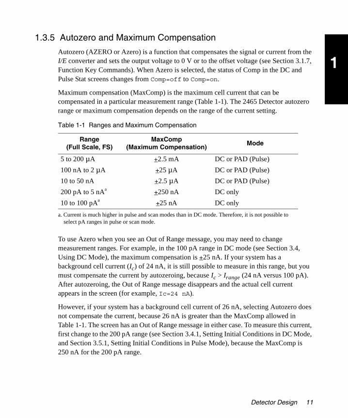
1.3.5 Autozero and Maximum Compensation
Autozero (AZERO or Azero) is a function that compensates the signal or current from the I/E converter and sets the output voltage to 0 V or to the offset voltage (see Section 3.1.7, Function Key Commands). When Azero is selected, the status of Comp in the DC and Pulse Stat screens changes from Comp=off to Comp=on.
Maximum compensation (MaxComp) is the maximum cell current that can be compensated in a particular measurement range (Table 1-1). The 2465 Detector autozero range or maximum compensation depends on the range of the current setting.
To use Azero when you see an Out of Range message, you may need to change measurement ranges. For example, in the 100 pA range in DC mode (see Section 3.4, Using DC Mode), the maximum compensation is +25 nA. If your system has a background cell current (Ic) of 24 nA, it is still possible to measure in this range, but you must compensate the current by autozeroing, because Ic > Irange (24 nA versus 100 pA). After autozeroing, the Out of Range message disappears and the actual cell current appears in the screen (for example, Ic=24 nA).
However, if your system has a background cell current of 26 nA, selecting Autozero does not compensate the current, because 26 nA is greater than the MaxComp allowed in Table 1-1. The screen has an Out of Range message in either case. To measure this current, first change to the 200 pA range (see Section 3.4.1, Setting Initial Conditions in DC Mode, and Section 3.5.1, Setting Initial Conditions in Pulse Mode), because the MaxComp is 250 nA for the 200 pA range.
Table 1-1 Ranges and Maximum Compensation
Range(Full Scale, FS)
MaxComp(Maximum Compensation)
Mode
5 to 200 µA +2.5 mA DC or PAD (Pulse)
100 nA to 2 µA +25 µA DC or PAD (Pulse)
10 to 50 nA +2.5 µA DC or PAD (Pulse)
200 pA to 5 nAa
a. Current is much higher in pulse and scan modes than in DC mode. Therefore, it is not possible to select pA ranges in pulse or scan mode.
+250 nA DC only
10 to 100 pAa +25 nA DC only
Detector Design 11
1
2465OG.book Page 12 Wednesday, November 7, 2007 10:33 AM
1.3.6 Startup Diagnostics
The 2465 Detector is equipped with a checksum verification and calculation diagnostic that is automatically invoked at startup. An eight-digit checksum value appears on the LCD display once the checksum is calculated.
Note: The correct checksum for your firmware version is in the Release Notes.
The 2465 Bootloader program is a special type of program that resides permanently in memory. It is responsible for initializing application-independent communication. It is also responsible for starting up the application software for the 2465 Detector.
1.3.7 Temperature Control
The detector oven, a heated flow cell and column compartment at the front of the 2465 Detector, is used to stabilize the detector’s performance. It can also be effective in aiding the chromatographic separation at the column. The heater stabilizes background current. The increase in temperature can increase noise, but reduces the rate of baseline drift.
1.4 Flow Cell Design
1.4.1 Flow Cell Operation
Before the flow cell can operate, it must be properly prepared, then switched on. The procedure to switch on the flow cell differs slightly for each mode. There are three ways to switch on the flow cell:
• From the front panel.
• Using the Cell On timed event. This input command can be used to switch on and stabilize the flow cell by means of a timer.
• Using a data system such as Empower™ software to control the 2465 Detector in remote mode.
Attention: Because an electrochemical detector is sensitive to environmental changes, do not operate it close to vents or a window.
A clear, level, smooth surface is required to allow the ventilation system under the 2465 Detector to work properly.
12 2465 Detector Theory of Operation

1
2465OG.book Page 13 Wednesday, November 7, 2007 10:33 AM
The standard flow cell is available with a glassy carbon (GC), platinum (Pt), gold (Au), or silver (Ag) working electrode (Figure 1-7). In combination with the spacer size set (25, 50, and 120 µm), a variety of detection volumes down to 11 nL can be attained. The inlet block is separated from the working electrode block by means of a spacer (not shown in Figure 1-7).
Figure 1-7 Flow Cell with a Salt-Bridge Reference Electrode
The in situ Ag/AgCl (ISAAC) reference electrode is recommended for standard applications. For special applications, the Hy-REF electrode is available. A third traditional reference electrode is the salt-bridge Ag/AgCl. This guide refers to the GC ISAAC reference electrode design as the most likely configuration for your use.
The 2465 Detector electrochemical flow cell has been developed for ultra-trace analysis in standard, microbore, and capillary LC-EC. The 2465 flow cell confined wall-jet configuration has proven to yield stable, reliable results. Considerable care is taken in the electrode material quality and finishing of the electrodes in the flow cell, which
Attention: To avoid damaging the flow cell, do not turn it on unless the fluid lines are connected and mobile phase is flowing.
Salt-Bridge Reference Electrode (sb REF)
Auxiliary Electrode (AUX)
Inlet Block
Working Electrode (WE) Block
Fingertight Fitting
Working Electrode
Fingertight Fitting
Outlet
Inlet
Flow Cell Design 13

1
2465OG.book Page 14 Wednesday, November 7, 2007 10:33 AM
contributes to overall performance of the detector. Additionally, this flow cell is simple to use and maintain.
The glassy carbon flow cell is tested before shipment. However, flow cells with a metal WE cannot be tested because the electrode surface changes chemically during use in an HPLC system with mobile phase. Performance of an electrochemical flow cell is best represented as the signal-to-noise ratio for a particular analyte selected by the user application.
1.4.2 Three-Electrode Potentiostat
The standard flow cell uses a three-electrode configuration (Figure 1-8). The working potential is set between the working electrode and the auxiliary electrode. The auxiliary electrode is kept at a precisely defined reference electrode potential by means of a potentiostat (an electronic feedback circuit that compensates for polarization effects at the electrodes).
Figure 1-8 Three-Electrode Electrochemical Cell
At the working electrode, which is kept at virtual ground, the electrochemical reaction takes place as electrons are transferred. This results in an electrical current to the I/E converter. An integrator can monitor the output voltage. The oxidation or reduction
Voltage Clamp
Potential
LC In
Reference Electrode
Auxiliary Electrode Working Electrode
Spacer
I/E Converter
Vout
LC Out
V+
-
+
-
14 2465 Detector Theory of Operation
1
2465OG.book Page 15 Wednesday, November 7, 2007 10:33 AM
reaction requires only two electrodes. However, the three-electrode configuration of the 2465 Detector has the following advantages over a two-electrode configuration:
• If the working potential is applied only over the auxiliary electrode versus the working electrode (without the reference electrode), the working potential would continuously change due to polarization effects at the electrodes, resulting in highly unstable working conditions.
• If the working potential is applied only over the reference electrode versus the working electrode (without the auxiliary electrode), the working potential would be very well defined. However, the potential of the reference electrode is only well defined if the current drawn is extremely low (pico-amperes), making it difficult to miniaturize the reference electrode.
• A three-electrode configuration combines the best of both electrodes. The reference electrode stabilizes the working potential and the auxiliary electrode can supply high currents. This results in the large dynamic range of a three-electrode system.
1.5 Electrodes
This section describes the selection of:
• Working electrode materials and diameters
• Spacer thickness
• Reference electrodes
1.5.1 Materials for Working Electrodes
Electrochemical detection puts high demands on the working electrode material, so the working electrode should be made of an electrochemically inert material. To avoid an irregular flow profile over the electrode and keep a constant diffusion layer, the electrode requires a very smooth surface. The 2465 electrodes are manufactured and tested to ensure that the fabrication process attains this requirement. Finally, the analyte of interest must be oxidized (or reduced) with favorable I/E characteristics, and a high signal must be obtained at a low working potential. For most applications, glassy carbon is the working electrode material of choice.
Other materials are favorable under certain circumstances. For example, you can use a silver working electrode for the analysis of iodide. The following oxidation reaction occurs for iodide at the silver working electrode:
Ag + I– → AgI + e–
Electrodes 15

1
2465OG.book Page 16 Wednesday, November 7, 2007 10:33 AM
where:
Ag = Silver
I = Iodide
e– = Electron
This reaction already takes place at a very low working potential (1 mV), which results in extremely high selectivity (Table 1-2). This allows the determination of iodide in urine samples with minimal sample pretreatment.
Another consideration in choosing a working electrode is the oxidation or reduction of mobile phase constituents or working electrode material, which occurs when the potential exceeds the limits in Table 1-2. At high positive working potentials, the water in the mobile phase electrolyzes and results in a strong increase of background current and noise. Formation of metal oxides, which increase background current, is a limiting factor for metal electrodes. Glassy carbon and platinum have the highest positive potential limits and are therefore often used in oxidative electrochemical detection. The use of platinum electrodes for negative potentials is limited by the ease of reducing hydrogen ions to hydrogen gas.
1.5.2 Working Electrode Diameter
The size of the working electrode is an important factor in LC-EC because it affects both the signal and the noise. Several working electrode diameters (nominally 0.7, 2, and 3 mm) are available for the standard flow cell. In a standard LC system the signal and the noise increase linearly with the working electrode diameter, so the S/N ratio remains approximately the same.
Table 1-2 Potential Limits and Applications for Working Electrodes
WE MaterialAlkaline Potential
Limits (V)Acidic Potential
Limits (V)Major Application
Glassy carbon (GC)
–1.50 to +0.60 –0.80 to +1.3 Catecholamines, neurotransmitters
Gold (Au) –1.25 to +0.75 –0.35 to +1.1 Carbohydrates
Platinum (Pt) –0.90 to +0.65 –0.20 to +1.3 Alcohols, glycols
Silver (Ag) –1.20 to +0.1 –0.55 to +0.4 Halides, cyanide
Copper (Cu) 0 to +0.6 – Amino acids, carbohydrates
16 2465 Detector Theory of Operation

1
2465OG.book Page 17 Wednesday, November 7, 2007 10:33 AM
In a micro-LC system, an increase in the working electrode diameter increases the noise more than the signal. Therefore, in micro-LC, a decrease of the working electrode diameter results in a better S/N ratio.
The choice for a flow cell is primarily based on the HPLC column diameter to obtain the best possible detection limit for a standard, microbore, or capillary column. The recommended combinations (Table 1-3) usually give the best S/N ratios. Other combinations that result in acceptable sensitivities are possible for many applications.
1.5.3 Spacer Thickness
The thickness of the spacer affects the linear flow velocity in the flow cell. The thinner the spacer, the smaller the cell volume, resulting in a higher linear flow velocity (Table 1-4).
The signal increases when using a thinner spacer, while the noise remains approximately constant, improving the signal-to-noise ratio (Figure 1-9).
Note: Figure 1-9 applies only under diffusion limiting current conditions (where the signal is limited only by diffusion).
Table 1-3 Recommended Flow Cells with Different Columns
Column Diameter Recommended Flow Cell
1 mm and larger 2-mm GC
Smaller than 1 mm 0.7-mm micro-GC
Table 1-4 Flow Cell Volume with Spacers
Spacer (µm)Cell Volume (µL) with
3-mm WECell Volume (µL) with
2-mm WECell Volume (µL) with
0.7-mm WE
25 0.15 0.08 0.011
50 0.29 0.16 0.022
120 0.71 0.38 0.053
Electrodes 17

1
2465OG.book Page 18 Wednesday, November 7, 2007 10:33 AM
Figure 1-9 Signal and Noise for Norepinephrine with Different Spacers
For any given flow rate, decreasing the spacer thickness increases the pressure drop over the flow cell, and eventually obstructs the flow. The minimum spacer thickness available is 25 µm.
Note: The flow cell requires one spacer. Apply the spacer with care. Overtightening the bolts can cause excessive pressure in the flow cell and increase the noise considerably.
1.5.4 ISAAC Reference Electrode
The ISAAC reference electrode is a simpler-to-use substitute for the classic salt-bridge type of reference electrode (see Section 1.5.6). The ISAAC reference electrode is in direct contact with the mobile phase. Installation is simple and there are no air bubbles to check.
Note: Waters recommends 2 mM chloride ions for the ISAAC reference electrode.
Either potassium or sodium chloride may be used. In many cases sodium chloride is preferred, to avoid solubility issues in the presence of other substances, such as perchlorate, which is often used in the sample preparation stage of some samples.
Note: The chloride concentration determines the potential. Therefore, each time a fresh mobile phase is prepared, it should contain the identical concentration of chloride ions.
Signals
Noise
18 2465 Detector Theory of Operation

1
2465OG.book Page 19 Wednesday, November 7, 2007 10:33 AM
The standard electrode potential of the Ag/AgCl electrode (in a 1.0 M chloride ion solution) for the following half-reaction is defined as E0:
AgCl(s) + e– <=> Ag(s) + Cl–
where E0 = 0.222 V.
The potential of the reference electrode is dependent on the chloride concentration, as described by the following equation:
–]
where:
E0 = Standard electrode potential
Eref = Potential of reference electrode
R = Gas constant (8.314 J M–1 K–1)
T = Absolute temperature (293 K)
F = Faraday’s constant
The potential (E) of the Ag/AgCl reference electrode at 2 mM KCl is 379 mV (Table 1-5). The potential difference (∆E) with the salt-bridge reference electrode in saturated KCl is 189 mV. Therefore, if an application is running at 800 mV (versus Ag/AgCl with saturated KCl), the potential setting using the ISAAC reference electrode (versus Ag/AgCl in 2 mM KCl) is:
800 – 189 = 611 mV
Table 1-5 Potential of the Ag/AgCl Reference Electrode
Cl– (mM) EAg/AgCl (mV) ∆E (mV)
3500 (saturated KCl) 190 0
2500 199 9
1500 212 22
500 240 50
100 280 90
20 321 131
10 338 148
8.0 344 154
6.0 351 161
Eref EAgCl0 RT
F-------– Cl[ln•=
Electrodes 19

1
2465OG.book Page 20 Wednesday, November 7, 2007 10:33 AM
The use of chloride in the mobile phase dictates the following restrictions:
• The ISAAC reference electrode is not recommended at a high working potential (greater than 1 V versus Ag/AgCl in 2 mM KCl) because Cl– is oxidized and contributes to the background current.
• In ion chromatography the addition of Cl– may lead to undesired chromatographic changes when dilute buffers are used.
• Using a silver working electrode is not recommended with the ISAAC reference electrode because the addition of Cl– to the mobile phase causes formation of an AgCl coating on the working electrode, leading to inactivation.
At high pH (above pH 10) or high modifier concentrations, the ISAAC reference electrode is less suitable and a Hy-REF electrode is recommended.
In addition, the ISAAC reference electrode is not usable with NH4+ buffers. The ISAAC
reference electrode should not be used with buffers that contain ligands which can form Ag complexes such as NH4
+.
Note: Waters recommends 2 mM chloride ions for the ISAAC reference electrode.
Maintaining a constant chloride concentration is required for the stable operation of the ISAAC reference electrode. The actual concentration of chloride can be affected not only by the presence of the potential applied, but also by the solubility equilibrium of all the species present in the mobile phase. The cases above are examples where the actual chloride concentration is changed, either due to chelation and/or precipitation, which results in lowering the actual concentration of chloride available to the reference electrode. This destabilizes the operation of the 2465 Detector ISAAC flow cell and is often manifested as a decreased response of analytes and increased noise during the analysis.
4.0 361 171
2.0 379 189
1.0 396 206
0.5 414 224
Table 1-5 Potential of the Ag/AgCl Reference Electrode (Continued)
Cl– (mM) EAg/AgCl (mV) ∆E (mV)
20 2465 Detector Theory of Operation

1
2465OG.book Page 21 Wednesday, November 7, 2007 10:33 AM
Table 1-6 shows the concentration of sodium chloride or potassium chloride needed to obtain various concentrations of chloride ions.
1.5.5 Hy-REF Reference Electrode
The Hy-REF is a hydrogen reference electrode, and its potential depends on the pH of the mobile phase. The Hy-REF electrode is fully comparable with the standard Ag/AgCl reference electrode for baseline stability and S/N ratio. The Hy-REF electrode is easier to use and virtually maintenance free because, like the ISAAC reference electrode, it does
Table 1-6 Mass of Anhydrous Sodium and Potassium Chloride per Liter for Various Molar Concentrations
Cl– Concentration (mMol/L)
Cl– Concentration
(Mol/L)NaCl (g/L) KCl (g/L)
0.1 0.0001 0.01 0.01
0.2 0.0002 0.01 0.01
0.5 0.0005 0.03 0.04
1 0.001 0.06 0.07
1.5 0.0015 0.09 0.11
2 0.002 0.12 0.15
3 0.003 0.18 0.22
4 0.004 0.23 0.30
5 0.005 0.29 0.37
10 0.010 0.58 0.75
15 0.015 0.88 1.12
20 0.020 1.17 1.49
25 0.025 1.46 1.86
30 0.03 1.75 2.24
50 0.05 2.92 3.73
100 0.1 5.84 7.46
500 0.5 29.22 37.28
1500 1.5 87.66 111.83
2500 2.5 146.10 186.38
3500 3.5 204.54 260.93
Electrodes 21

1
2465OG.book Page 22 Wednesday, November 7, 2007 10:33 AM
not require a salt bridge. Air bubbles cannot be trapped (as when a salt-bridge Ag/AgCl is used). No filling solution or addition of Cl− to the mobile phase is required, and the Hy-REF is compatible with high percentages of common organic modifiers such as methanol and acetonitrile.
Depending on the pH of the mobile phase, the potential setting of the working electrode compared to the Hy-REF electrode may differ significantly from that of the Ag/AgCl reference electrode. Current-potential (I/E) curves for the typical Ag/AgCl reference electrode show a shift of more than 200 mV at pH 3.1 (when working with catecholamines); no shift appears at pH 12 (such as with PAD of carbohydrates). Therefore, when using the Hy-REF electrode, first construct a hydrodynamic (or scanning) voltammogram. Table 1-7 shows the potential of the Hy-REF electrode and the Ag/AgCl electrodes at different pH values.
If an Ag/AgCl REF is replaced by a Hy-REF electrode, the pH effect must be taken into account. The relationship is described by:
EHy-REF = EAg/AgCl – 328 + 29.9 pH
where E = Potential.
For example, a working potential of 800 mV (versus an Ag/AgCl electrode with saturated KCl) at pH 3 has to be changed to:
EHy-REF = 800 – 328 + 29.9 × 3 = 561.7 mV (versus a Hy-REF electrode)
1.5.6 Salt-Bridge Ag/AgCl Reference Electrode
The reference electrode of the salt-bridge Ag/AgCl type consists of a silver rod coated with solid AgCl, immersed in a solution of saturated KCl containing KCl crystals (see Figure 4-8 for a schematic representation of the Ag/AgCl reference electrode). Electrical contact with the other electrodes in the flow cell is made through a salt bridge consisting of a wetted cotton wool frit, which is electrically conducting and slows down leakage of
Table 1-7 Cell Potential (Hy-REF and Ag/AgCl Electrodes) Versus pH
pH EHy-REF – Ag/AgCl (mV)
3.3 232
6.2 130
7.5 90
11.8 0
22 2465 Detector Theory of Operation
1
2465OG.book Page 23 Wednesday, November 7, 2007 10:33 AM
KCl. The closed reservoir prevents contamination. This reference electrode for the standard flow cell is factory-filled with KCl.
For certain applications another chloride salt is required. For example:
• Sodium chloride must be used instead of potassium chloride in mobile phases containing perchlorate because potassium perchlorate precipitates and clogs the cotton wool frit.
• At high modifier percentages, the reference electrode must be filled with lithium chloride because the potassium salt is prone to precipitation.
1.6 Principles of Detector Operation
To use the 2465 Detector effectively, you should be familiar with the operational modes, the fluidics including the configured flow cell and electrodes, the electronic design of the detector, and the theory and principles of operation. The operational modes of the 2465 Detector are:
• Section 1.6.1, DC Mode
• Section 1.6.2, Pulse (PAD) Mode
• Section 1.6.3, Scan Mode
1.6.1 DC Mode
Direct current (DC) mode measures the current of a sample at a fixed potential. A hydrodynamic voltammogram is constructed using DC mode by running several chromatograms at different working potentials (see Section 3.7.2, Constructing a Scanning Voltammogram). Both peak height and background current are plotted against the working potential as part of method optimization.
DC Mode Primary Parameters
The primary parameters used in DC mode are as follows:
• Potential – Cell potential (Ec), measured in volts.
• Range/Sensitivity – Parameter that sets the current range so that the largest peaks are on scale; similar to attenuation in an absorbance detector.
• Filter Time Constant – A filter that is applied to smooth the data. High frequency noise is efficiently removed and chromatographic peaks can be detected with a better signal-to-noise ratio.
Principles of Detector Operation 23

1
2465OG.book Page 24 Wednesday, November 7, 2007 10:33 AM
• Max Compensation – The largest background current that can be autozeroed. It is determined by the Range/Sensitivity setting. This is the maximum range attainable when the detector is autozeroed. The cell potential reading on the display shows the actual current, while the analog output voltage is set to zero. When the autozero is executed, the autozero range varies with output analog potential range.
• Offset – Compensation for background current, expressed as a percentage of the range setting. You can set a maximum offset of +50% and –50% in 5% steps. For example, 20% is a 200-mV offset when the maximum output is 1.0 V (2 V at maximum 10.0 V).
• Polarity – Setting of the data signal as positive or negative; applies to the digital and analog outputs. The polarity of the output can be reversed. Oxidative and reductive analysis have opposite currents. For data acquisition, chromatographic peaks traditionally have a positive amplitude.
• Temperature – Temperature control of the detector oven (with mobile phase, flow cell, and column) to improve performance. Electrochemistry is susceptible to temperature fluctuations because the mobile phase oxidation or reduction contributes significantly to the background noise, and these reactions are influenced by changes in room temperature. Elevation of the temperature above ambient can reduce the sensitivity of electrochemistry to environmental changes.
• Methods Programmability – Ability to program the 2465 Detector (using timed events to change the parameters) and run using the Events feature. Method time files 1 to 5 are reserved for DC mode. The parameters are as follows:
– Potential (cell potential Ec)
– Filter Time Constant
– Range
– Offset
– Auto Zero Enable
– Output Events
– End Cycle or Run Time
1.6.2 Pulse (PAD) Mode
Pulsed amperometric detection (PAD) or pulse mode regenerates the working electrode at a frequency of 0.5 to 3 Hz by applying a series of potential changes. This is particularly useful for certain applications where the working electrode is rapidly fouled due to adsorption of insoluble reaction products. A well-known application area of PAD is analysis of carbohydrates.
24 2465 Detector Theory of Operation

1
2465OG.book Page 25 Wednesday, November 7, 2007 10:33 AM
Pulse mode differs from DC mode as follows:
• The output signal is sampled during only a part of the total pulse cycle. During the sampling time (ts) the signal generated at the working electrode is collected, and this value is sent to the detector output. The output is refreshed each pulse cycle. Therefore, the frequency of data output is determined by the pulse duration.
• When the data acquisition rate of the data system or integrator is higher than the pulse cycle frequency, a typical stepwise pattern may appear in the chromatogram. Ideally, the data acquisition rate should be matched to the detector output. The data system’s sampling rate should be no less than twice the signal frequency, expressed as points per second.
• The background or cell current is usually higher in pulse mode (100 to 1000 nA) than in DC mode. Only the nano- and microampere ranges are available in the pulse mode.
• After prolonged use of the flow cell with a gold working electrode in pulse mode, a brown precipitate forms on the auxiliary electrode. This coating may electrically isolate the auxiliary electrode and increase the noise. Cleaning the auxiliary electrode approximately every six months with steel wool prevents this.
• Hy-REF electrodes are maintenance free and are particularly appropriate for carbohydrate analysis. Ag/AgCl reference electrodes are less suitable due to silver oxide formation, and they require regular (monthly) maintenance.
• For carbohydrate analysis, only CO2-free sodium hydroxide should be used since carbonate anions may disturb the ion exchange chromatography. The CO2-free sodium hydroxide is available from several suppliers as a 50% solution (19.2 M). NaOH pellets are not recommended because of their high CO2 content.
Carbonate-free solutions are best prepared by adding the appropriate volume of 50% (wgt:wgt) sodium hydroxide solution to CO2-free HPLC-grade water. Boiling and vacuum sonication remove CO2 from water before the addition of NaOH.
• The accuracy of certain pH electrodes is poor at high pH. For applications at high pH it is sometimes better to calculate the pH from the OH– concentration.
• Organic modifiers (acetonitrile) are not recommended.
Caution: To prevent damage to the working electrode, do not touch the working electrode with steel wool.
Principles of Detector Operation 25
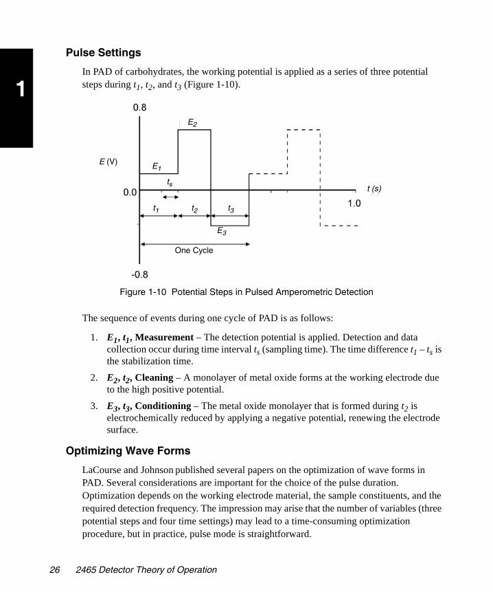
1
2465OG.book Page 26 Wednesday, November 7, 2007 10:33 AM
Pulse Settings
In PAD of carbohydrates, the working potential is applied as a series of three potential steps during t1, t2, and t3 (Figure 1-10).
Figure 1-10 Potential Steps in Pulsed Amperometric Detection
The sequence of events during one cycle of PAD is as follows:
1. E1, t1, Measurement – The detection potential is applied. Detection and data collection occur during time interval ts (sampling time). The time difference t1 – ts is the stabilization time.
2. E2, t2, Cleaning – A monolayer of metal oxide forms at the working electrode due to the high positive potential.
3. E3, t3, Conditioning – The metal oxide monolayer that is formed during t2 is electrochemically reduced by applying a negative potential, renewing the electrode surface.
Optimizing Wave Forms
LaCourse and Johnson published several papers on the optimization of wave forms in PAD. Several considerations are important for the choice of the pulse duration. Optimization depends on the working electrode material, the sample constituents, and the required detection frequency. The impression may arise that the number of variables (three potential steps and four time settings) may lead to a time-consuming optimization procedure, but in practice, pulse mode is straightforward.
One Cycle
E (V)
E2
E1
E3
t1 t2 t3
tst (s)
26 2465 Detector Theory of Operation

1
2465OG.book Page 27 Wednesday, November 7, 2007 10:33 AM
The WE material determines the potential for the cleaning steps, E2 and E3. At alkaline pH, gold oxide is already formed at E2 > +200 mV (versus Ag/AgCl). At a higher potential, the formation of a metal oxide layer is accelerated and you may choose a shorter time setting. In practice, an E2 value of +650 to +750 mV during 200 ms (t2) gives good results.
The choice of t3 depends on the potential E3 and the t2 and E2 setting. The duration of t3 and the magnitude of E3 must be large enough to completely remove the metal oxide. Reductive dissolution already occurs at E3 < 0 mV, but a more negative voltage speeds up this process (Table 1-8). For example, an E3 value of –800 mV during 200 ms or –300 mV during 360 ms can be used.
The measured potential is compound dependent, and literature data can be used as a starting point for further optimization. Andrews and King describe the optimization of waveforms and the selection of pulse potentials.
A sampling time (ts) can be chosen between 20 and 100 ms in 20-ms steps. These are multiples of 50 Hz to prevent noise due to oscillations of the AC power supply. Increasing ts results in an increased signal up to a certain limit. A limiting factor is the accumulation of adsorbed species at the working electrode, attenuating the signal. Another consideration for all time settings is that increasing the time decreases the detection frequency.
Stabilization Time
Before sampling, a stabilization time is applied (t1), which determines the level of the background current. For example, if t1 = 100 ms and ts = 100 ms, the current is not stabilized before sampling (t1 – ts = 0 ms). Depending on the potential settings of E2 and E3, a large positive or negative background current (microamperes) may be detected, seriously limiting the detection. A stabilization time of 100 to 400 ms is often used.
Table 1-8 Selection of Pulse Parameters
Pulse Parameter Desired Valuea
a. mV relative to the peak potential for the reduction of gold oxide
Duration Sampling
1 E1 0 400 (t1) 100 (ts)
2 E2 +650 200 (t2)
3 E3 –650 200 (t3)
Principles of Detector Operation 27
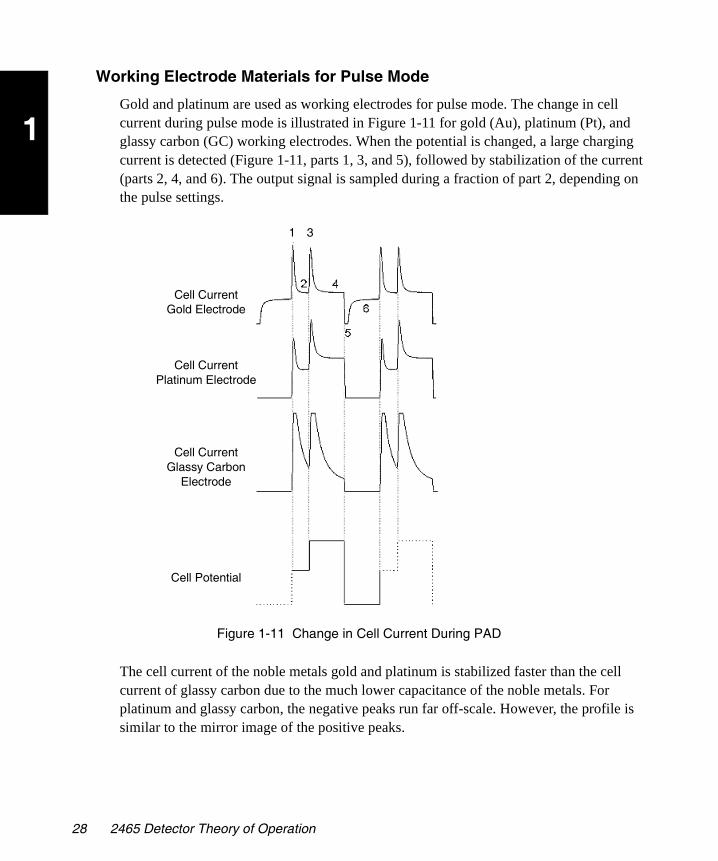
1
2465OG.book Page 28 Wednesday, November 7, 2007 10:33 AM
Working Electrode Materials for Pulse Mode
Gold and platinum are used as working electrodes for pulse mode. The change in cell current during pulse mode is illustrated in Figure 1-11 for gold (Au), platinum (Pt), and glassy carbon (GC) working electrodes. When the potential is changed, a large charging current is detected (Figure 1-11, parts 1, 3, and 5), followed by stabilization of the current (parts 2, 4, and 6). The output signal is sampled during a fraction of part 2, depending on the pulse settings.
Figure 1-11 Change in Cell Current During PAD
The cell current of the noble metals gold and platinum is stabilized faster than the cell current of glassy carbon due to the much lower capacitance of the noble metals. For platinum and glassy carbon, the negative peaks run far off-scale. However, the profile is similar to the mirror image of the positive peaks.
Cell CurrentGold Electrode
Cell Potential
1 3
Cell CurrentPlatinum Electrode
Cell CurrentGlassy Carbon
Electrode
28 2465 Detector Theory of Operation
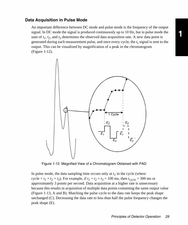
1
2465OG.book Page 29 Wednesday, November 7, 2007 10:33 AM
Data Acquisition in Pulse Mode
An important difference between DC mode and pulse mode is the frequency of the output signal. In DC mode the signal is produced continuously up to 10 Hz, but in pulse mode the sum of t1, t2, and t3 determines the observed data acquisition rate. A new data point is generated during each measurement pulse, and once every cycle, the ts signal is sent to the output. This can be visualized by magnification of a peak in the chromatogram (Figure 1-12).
Figure 1-12 Magnified View of a Chromatogram Obtained with PAD
In pulse mode, the data sampling time occurs only at t1 in the cycle (where cycle = t1 + t2 + t3). For example, if t1 = t2 = t3 = 100 ms, then tcycle = 300 ms or approximately 3 points per second. Data acquisition at a higher rate is unnecessary because this results in acquisition of multiple data points containing the same output value (Figure 1-13, A and B). Matching the pulse cycle to the data rate keeps the peak shape unchanged (C). Decreasing the data rate to less than half the pulse frequency changes the peak shape (E).
E2E2
E1 E1
E3 E3
1 Cycle
Principles of Detector Operation 29

1
2465OG.book Page 30 Wednesday, November 7, 2007 10:33 AM
Figure 1-13 Chromatograms Acquired at Different Data Rates
Pulse Mode Primary Parameters
In PAD for carbohydrate detection, the working potential is applied as a series of three potentials: t1, t2, and t3 (see Figure 1-12). These timed events during one cycle of PAD correspond to changes in potential applied across the flow cell electrodes. The following primary parameters are available for the timed events:
• t1 – Time when the detection potential is applied. Detection and data collection occur during time interval or sampling total time.
• t2 – Time when a monolayer of metal oxide forms at the working electrode due to the high positive potential.
Scan in Figure 1-13
Pulse Cycle Time Factor
A 5.0
B 2.5
C 1.2
D 0.6
E 0.3
30 2465 Detector Theory of Operation

1
2465OG.book Page 31 Wednesday, November 7, 2007 10:33 AM
• t3 – Time when the metal oxide monolayer that is formed during t2 is electrochemically removed by applying a negative potential, renewing the electrode surface.
• ts – Sampling time when the current is monitored.
• Potential E1, E2, and E3 – Applied cell potentials at times t1, t2, and t3, respectively.
• Range/Sensitivity – User setting for the current range so that the largest peaks are on scale; equivalent to attenuation in an absorbance detector. The effective working range for pulse mode is lower than for DC mode.
• Max Compensation – The largest background current that can be autozeroed. It is determined by the Range/Sensitivity setting. This is the maximum current that can be autozeroed from the analog signal. The potential range for pulse mode is limited as the current is higher so a small range is available.
• Offset – Compensation for background current, expressed as a percentage of the range setting.
• Polarity – Applies to the digital and analog outputs; allows you to set the data signal as positive or negative.
• Temperature – Control of the temperature of the mobile phase, flow cell, and column to significantly improve performance. By elevating the temperature above ambient, the sensitivity of electrochemistry to environmental changes can be reduced. Electrochemistry is susceptible to temperature because the mobile phase oxidation or reduction contributes significantly to the background noise, and these reactions are influenced by changes in room temperature.
• Methods Programmability – Allows you to program the 2465 Detector using timed events to change the parameters. Method time files 6 to 9 are reserved for pulse mode. You can change the following parameters:
– Potential (cell potentials E1, E2, and E3)
– Filter Time Constant
– Range
– Offset
– Auto Zero Enable
– Output Events
– End Cycle or Run Time
Principles of Detector Operation 31
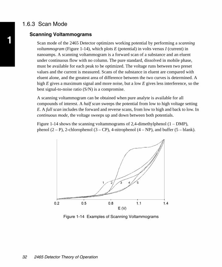
1
2465OG.book Page 32 Wednesday, November 7, 2007 10:33 AM
1.6.3 Scan Mode
Scanning Voltammograms
Scan mode of the 2465 Detector optimizes working potential by performing a scanning voltammogram (Figure 1-14), which plots E (potential) in volts versus I (current) in nanoamps. A scanning voltammogram is a forward scan of a substance and an eluent under continuous flow with no column. The pure standard, dissolved in mobile phase, must be available for each peak to be optimized. The voltage runs between two preset values and the current is measured. Scans of the substance in eluent are compared with eluent alone, and the greatest area of difference between the two curves is determined. A high E gives a maximum signal and more noise, but a low E gives less interference, so the best signal-to-noise ratio (S/N) is a compromise.
A scanning voltammogram can be obtained when pure analyte is available for all compounds of interest. A half scan sweeps the potential from low to high voltage setting E. A full scan includes the forward and reverse scans, from low to high and back to low. In continuous mode, the voltage sweeps up and down between both potentials.
Figure 1-14 shows the scanning voltammograms of 2,4-dimethylphenol (1 – DMP), phenol (2 – P), 2-chlorophenol (3 – CP), 4-nitrophenol (4 – NP), and buffer (5 – blank).
Figure 1-14 Examples of Scanning Voltammograms
32 2465 Detector Theory of Operation
1
2465OG.book Page 33 Wednesday, November 7, 2007 10:33 AM
Scan Mode Primary Parameters
• E1 Potential – Potential applied at the beginning of the scan cycle.
• E2 Potential – Potential reached at the end of the scan cycle.
• Scan Cycle – Length of the cycle, which can be half, full, or continuous. Half indicates a single ramp between E1 and E2. Full indicates a ramp from E1 to E2, then from E2 to E1. Continuous indicates that the full ramp is repeatedly cycled.
• Range/Sensitivity – Setting for the current range so that the scan current remains on scale; equivalent to attenuation in an absorbance detector.
• Offset – Compensation for background current, expressed as a percentage of the range setting.
• Temperature – Control of the temperature of the mobile phase, flow cell, and column to significantly improve performance. By elevating the temperature above ambient, the sensitivity of electrochemistry to environmental changes can be reduced. Electrochemistry is susceptible to temperature because the mobile phase oxidation or reduction contributes significantly to the background noise, and these reactions are influenced by changes in room temperature.
Note: The Auto Zero Enable key is available during the scan.
1.7 References
The following references contain additional information:
• R.W. Andrews and R.M. King, “Selection of potentials for pulsed amperometric detection of carbohydrates at gold electrodes,” Anal. Chem., 62: 1990, pp. 2130–2134.
• D.C. Johnson, D. Dobberpuhl, R. Roberts, and P. Vandeberg, “Review. Pulsed amperometric detection of carbohydrates, amines and sulphur species in ion chromatography - the current state of research,” J. Chromatogr., Vol. 640: 1993, pp. 79–96.
• D.C. Johnson and W.R. LaCourse, “LC with pulsed ECD at gold and platinum electrodes,” Anal. Chem., Vol. 62: 1990, pp. 589A–597A.
• W.R. LaCourse and D.C. Johnson, “Optimization of waveforms for pulsed amperometric detection of carbohydrates following separation by LC,” Carbohydrate Research, Vol. 215: 1991, pp. 159–178.
• W.R. LaCourse and D.C. Johnson, “Optimization of waveforms for pulsed amperometric detection of carbohydrates based on pulsed voltammetry,” Anal. Chem. Vol. 65: 1993, pp. 50–55.
References 33

1
2465OG.book Page 34 Wednesday, November 7, 2007 10:33 AM
34 2465 Detector Theory of Operation

2
2465OG.book Page 35 Wednesday, November 7, 2007 10:33 AM
Chapter 2 Installing the 2465 Detector
Use this chapter to install the 2465 Detector (Figure 2-1).
Figure 2-1 Major Steps for Installing the 2465 Detector
2.1 Site Selection and Power Requirements
2.1.1 Site Selection
Figure 2-2 shows the dimensions of the 2465 Detector. Install the 2465 Detector in an area that meets the requirements in Table 2-1.
End
Make Fluidic Connections
Make Signal Connections and Connect Other
Devices
Start
Select Appropriate Site
Unpack and Inspect
Make Power Connections
Make Signal Connections and Connect Other
Devices
Site Selection and Power Requirements 35

2
2465OG.book Page 36 Wednesday, November 7, 2007 10:33 AM
Figure 2-2 Dimensions of the 2465 Detector
Table 2-1 Installation Site Requirements
Parameter Requirement
Operating temperature range 39 to 104 °F (4 to 40 °C)
Storage temperature range –104 to 158 °F (–40 to 70 °C)
Relative humidity range 20 to 80%, noncondensing
Storage humidity range 0 to 90%, noncondensing
Bench space 6 inches (15.25 cm) clearance at rear; access to power switch and power cord; clean, level, smooth surface
Vibration Negligible
Static electricity Negligible
17.3 Inches (44 cm)
17.3 Inches (44 cm)
8.7 Inches (22 cm)
36 Installing the 2465 Detector

2
2465OG.book Page 37 Wednesday, November 7, 2007 10:33 AM
2.1.2 Power Requirements
The 2465 Detector requires:
• Grounded alternating current (AC) power source
• Minimal power transients and fluctuations
• Line voltage of 100 to 240 VAC; power is auto-selecting (100 to 240 V)
• Power consumption of 260 Volt Amps (VA)
• Two 2.5-AT fuses
Power Grounded AC, 100 to 240 VAC (auto-selecting), 50/60 Hz
Weight 30.9 lb (14 kg) without flow cell or column
Attention: You must mount the 2465 Detector on a level surface to allow the drip management system (drain tube) to work properly. You can connect a drain tube to a waste container to collect solvent leaks from the detector oven.
A clear, level, smooth surface is required to allow the ventilation system under the 2465 Detector to work properly.
Ensure that the power (on/off) switch and power cord are always accessible.
Caution: To avoid electrical shock, power off the 2465 Detector and unplug the power cord before you make connections or replace a fuse.
Attention: Use shielded cable(s) for all I/O connections with other devices. Thoroughly connect the shielding to common.
The manufacturer will not accept any liability for damage, direct or indirect, caused by connecting this instrument to devices that do not meet the relevant safety standards.
Table 2-1 Installation Site Requirements (Continued)
Parameter Requirement
Site Selection and Power Requirements 37
2
2465OG.book Page 38 Wednesday, November 7, 2007 10:33 AM
2.2 Unpacking and Inspecting the 2465 Detector
The 2465 Detector is packed and shipped in one carton that contains the following items:
• Waters 2465 Electrochemical Detector
• Power cord (110 V or 240 V, as appropriate for your location)
• Certificate of Validation
• Declaration of Conformity
• Waters 2465 Electrochemical Detector Operator’s Guide
• Startup Kit (Table B-8)
• Flow cell (not shipped in the 2465 Detector carton; at least one flow cell must be purchased separately). Table B-1 lists the flow cells that are available. Table B-2 through Table B-7 list the components in each flow cell kit.
To unpack the 2465 Detector:
1. Inspect the carton for possible damage when it arrives. Immediately inform the transport company if you see any damage.
2. Remove the packing material, accessory kit, envelope, and power cord from the carton.
Note: Keep the carton and packing material for future transport and/or storage as they are designed for optimum protection.
3. With both hands on the sides of the 2465 Detector, lift it from the carton (Figure 2-3).
Attention: To prevent damage to the door, never lift the 2465 Detector by its door, but only by its sides.
38 Installing the 2465 Detector

2
2465OG.book Page 39 Wednesday, November 7, 2007 10:33 AM
Figure 2-3 Unpacking the 2465 Detector
4. Remove the plastic wrap.
5. Inspect the detector carefully for possible damage and make sure that all ordered items are included.
Note: Contact your supplier if you see any damage or if any items are not included.
6. Ensure that the instrument serial number, located on the left side panel, corresponds to the number on the Certificate of Structural Validation.
7. If you see any damage or discrepancy when you inspect the contents of the carton, immediately contact the shipping agent and Waters Technical Service at 800 252-4752, for U.S. and Canadian customers. Other customers, call your local Waters subsidiary or your local Waters Technical Service Representative, or call Waters corporate headquarters in Milford, Massachusetts 01757 (U.S.A.).
2.3 Making Electrical Power Connections
To connect the 2465 Detector to the AC power supply:
1. Make sure that the power switch is in the 0 (off) position (Figure 2-4).
2. Plug the receptacle end of the power cord into the AC input connector on the rear panel of the detector.
3. Plug the other end of the power cord into a properly grounded AC power source.
Lift HereLift Here, Not at the Front
Making Electrical Power Connections 39
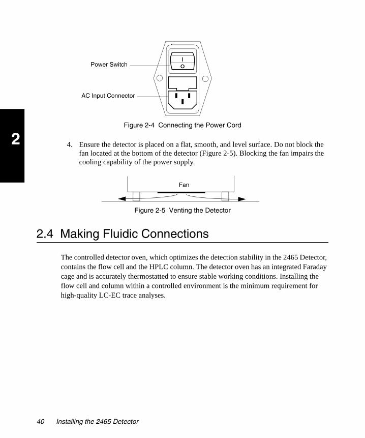
2
2465OG.book Page 40 Wednesday, November 7, 2007 10:33 AM
Figure 2-4 Connecting the Power Cord
4. Ensure the detector is placed on a flat, smooth, and level surface. Do not block the fan located at the bottom of the detector (Figure 2-5). Blocking the fan impairs the cooling capability of the power supply.
Figure 2-5 Venting the Detector
2.4 Making Fluidic Connections
The controlled detector oven, which optimizes the detection stability in the 2465 Detector, contains the flow cell and the HPLC column. The detector oven has an integrated Faraday cage and is accurately thermostatted to ensure stable working conditions. Installing the flow cell and column within a controlled environment is the minimum requirement for high-quality LC-EC trace analyses.
AC Input Connector
Power Switch
Fan
40 Installing the 2465 Detector

2
2465OG.book Page 41 Wednesday, November 7, 2007 10:33 AM
The installation procedures for the fluidic components are listed in Figure 2-6.
Figure 2-6 Making the HPLC Connections
Required Materials
• Flow cell (standard or micro)
• Tubing
Materials Required But Not Supplied
• HPLC pump
• Mobile phase(s) in reservoir(s)
– HPLC-grade water
Attention: The manufacturer will not accept any liability for damage, direct or indirect, caused by connecting this instrument to devices that do not meet the relevant safety standards.
Attention: The pump must be able to deliver flow rates between the following flow cell specifications:
Flow rate for standard flow cell: 25 µL/min to 2.0 mL/min
Flow rate for micro flow cell: 1 µL/min to 2.0 mL/min
Maximum pressure, standard flow rate: 40 psi (2.76 bar, 276 kPa)
Attention: Always position the 2465 Detector as the last detector in the series (if the system includes more than one detector).
End
Install Solvent Reservoirs and Inline
Degasser
Check for Leaks and Passivate System
Install Column and Flow Cell
Start
Install Pump, Pulse Dampener (Optional),
and Injector
Electrochemically Clean the Column
Fill Flow Cell with Buffered Mobile
Phase
Install Waste Container
Making Fluidic Connections 41

2
2465OG.book Page 42 Wednesday, November 7, 2007 10:33 AM
– HPLC buffer; for ISAAC reference electrode only, with 2 mM chloride ions (KCl or NaCl)
– 50% methanol in HPLC-grade water for reversed-phase HPLC
• HPLC column, preconditioned
• Drip management system, tubing, and waste container
• 15% nitric acid for passivation
• Helium (certain applications)
• Stainless steel tubing (certain applications)
• PEEK® tubing
Optional Materials
• Solvent inlet filters (recommended)
• Solvent tray, up to 14.25 inches (36.2 cm) × 8.25 inches (21.0 cm)
• Inline degasser (either vacuum degassing or sparging with helium)
• Pulse dampener
• Injector
• Inline filters and/or guard column
Caution: When you handle solvents, change tubing, or operate the 2465 Detector in general, always observe good laboratory practices. Know the physical and chemical properties of the solvents. Refer to the Material Safety Data Sheets for the solvents in use.Caution: Wear protective clothing when handling 15% nitric acid.
Attention: Passivation should include only the metal parts of the HPLC system. Disconnect all parts that are not acid-resistant (such as nylon inlet filters, degasser, pulse dampener, column, and flow cell) during passivation. Do not expose columns or flow cells to 15% nitric acid.
Attention: Do not use a metal frit to filter the mobile phase.
Attention: The manufacturer will not accept any liability for damage, direct or indirect, caused by connecting this instrument to devices that do not meet the relevant safety standards.
42 Installing the 2465 Detector

2
2465OG.book Page 43 Wednesday, November 7, 2007 10:33 AM
2.4.1 Installing the 2465 Detector
To install the 2465 Detector:
1. Remove any tape or protective straps or foam packing from the detector and open the door from the left side (Figure 2-7).
Figure 2-7 2465 Detector Oven
Attention: The 2465 Detector uses standard analytical flow cells that are pressure-rated at 40 psi (2.76 bar, 276 kPa). The micro flow cells are also pressure-rated at 40 psi (2.76 bar, 276 kPa). To prevent damage, do not connect any tubing or device that might cause backpressure to exceed the pressure rating of the tubing or flow cell.
Attention: Do not operate the 2465 Detector with the standard flow cell above a flow rate of 2.0 mL/min or 40 psi (2.76 bar, 276 kPa) backpressure. With a micro flow cell, do not exceed 25 µL/min or 40 psi (2.76 bar, 276 kPa) backpressure. This can cause the pressure to exceed the rating of the tubing or flow cell.
Fan
Fan
Female 9-Pin Connector
Flow Cell Clamp
6-mm Column Clamps
Inlet Tubing Hole
Outlet Tubing Hole
Door
Drain Hole for Accidental Leaks
Making Fluidic Connections 43

2
2465OG.book Page 44 Wednesday, November 7, 2007 10:33 AM
2. If your column requires column clamps larger than the 6-mm clamps already installed, remove the 6-mm clamps and install two 12-mm column clamps.
3. Install a pump (see the manufacturer’s instructions), pulse dampener (optional), waste container, solvent tray (optional), and mobile phase reservoir (Figure 2-8):
a. Connect tubing from the pump to the pulse dampener.
b. Connect tubing from the pulse dampener to the waste container, temporarily bypassing the detector.
Figure 2-8 Installing the External Pump and Pulse Dampener
Note: Waters recommends that the mobile phase contain 2 mM chloride (KCl or NaCl) ions when using the ISAAC reference electrode.
c. Fill a mobile phase reservoir with mobile phase. Place inlet filters on the tubing. Place a solvent tray on top of the detector, then place the reservoirs in the solvent tray.
Caution: When you handle solvents, change tubing, or operate the 2465 Detector in general, always observe good laboratory practices. Know the physical and chemical properties of the solvents. Refer to the Material Safety Data Sheets for the solvents in use.
Pump
Pulse Dampener Waste Container
Solvent Tray
Mobile Phase Reservoir
44 Installing the 2465 Detector
2
2465OG.book Page 45 Wednesday, November 7, 2007 10:33 AM
d. Connect the tubing from the mobile phase reservoir to the pump.
4. You can install an inline degasser (optional) to prevent passage of air bubbles through the flow cell.
Note: Air bubbles passing through the flow cell can create unacceptable noise levels and spikes.
5. Power on the pump and ensure that the system has no leaks, then stop the pump.
6. Passivate all metal parts of the HPLC system (except parts that are not acid-resistant) as follows:
a. Make sure that all parts that are not acid-resistant (such as nylon inlet filters, column, and flow cell) are not connected during this step.
b. Disconnect the mobile phase reservoir and connect a reservoir containing 15% nitric acid.
c. Flush nitric acid for 20 minutes through the pump, pump tubing, and dampener, then to the waste container.
d. Thoroughly flush the HPLC system with HPLC-grade water. Check the pH of the effluent until it is neutral to make sure that all traces of nitric acid are flushed from the tubing and pulse dampener.
Attention: Do not use a metal frit to filter the mobile phase.
Caution: When you handle solvents, change tubing, or operate the 2465 Detector in general, always observe good laboratory practices. Know the physical and chemical properties of the solvents. Refer to the Material Safety Data Sheets for the solvents in use.Caution: Wear protective clothing when handling 15% nitric acid.
Attention: Ensure that all parts that are not acid-resistant (such as the nylon inlet filters, column, and flow cell) are disconnected during passivation. Do not passivate the 2465 Detector flow cell.
Attention: If you plan to use an ISAAC reference electrode, flush the system with mobile phase containing 2 mM chloride (KCl or NaCl) ions.
Making Fluidic Connections 45

2
2465OG.book Page 46 Wednesday, November 7, 2007 10:33 AM
e. Remove the temporary tubing between the pulse dampener and the waste container.
f. Place tubing through the upper hole in the chassis and connect it to the waste container. Secure the tubing in the waste container with the tubing touching the side.
Note: Set a waste tray under the detector to collect any leaks from the detector oven. Do not block the fan located at the bottom of the detector (Figure 2-5). Blocking the fan impairs the cooling capability of the power supply.
g. Place tubing through the lower hole and connect the mobile phase reservoir to the pump. Place the reservoir higher than the flow cell, such as in the solvent tray on top of the detector.
2.4.2 Connecting a Column
The column must be electrochemically clean for use in the 2465 Detector. A new column is not considered electrochemically clean. See the manufacturer’s instructions for more information.
Select the appropriate size flow cell and spacer for your column ID (see Table 1-3).
To connect the tubing to the column:
1. Attach a compression fitting and ferrule.
2. Connect the inlet tubing from the pump to the pulse dampener (optional) and autosampler (optional), then to the flow cell. Ensure the tubing is seated firmly, then tighten the compression screw.
3. Connect waste tubing to the column outlet and route the tubing through the top hole in the side of the chassis to a waste container. To provide constant backpressure, place the waste container above the 2465 Detector in a solvent tray, and ensure the tubing touches the side of the container.
4. Install the column in the column clamps.
5. Thoroughly precondition the column to ensure that it is electrochemically clean.
Caution: When you handle solvents, change tubing, or operate the 2465 Detector in general, always observe good laboratory practices. Know the physical and chemical properties of the solvents. Refer to the Material Safety Data Sheets for the solvents in use.
46 Installing the 2465 Detector

2
2465OG.book Page 47 Wednesday, November 7, 2007 10:33 AM
6. For reversed-phase (RP-HPLC) columns:
a. Flush with 50% methanol in water for 3 days at a low flow rate. Drain to a covered waste container.
b. Flush with 10 column volumes of HPLC-grade water before switching to the mobile phase to prevent precipitation of buffer salts.
7. Equilibrate the column by running 10 column volumes of buffered mobile phase through the column.
8. Once the column is clean, place an inline filter after the injector and before the column to protect both the column and the flow cell from particulates.
9. If the 2465 Detector is used for reductive ECD (at a negative working potential), take the following additional actions to remove oxygen from the mobile phase:
• Degas with helium.
• Use stainless steel tubing everywhere (because it is impermeable to oxygen), except when it is in direct contact with the flow cell (due to possible electrical interference).
2.4.3 Installing the Flow Cell
Note: Familiarize yourself with the force on the flow cell bolts, since overtightening of the bolts markedly deteriorates the S/N ratio and eventually the cell itself. The flow cell is assembled properly when it arrives and the force on the bolts is preset to 30 Ncm. To
Attention: To prevent unacceptably high background current and substantial fouling of the working electrode, use a column that is electrochemically clean. A new column is not electrochemically clean.
Attention: Waters strongly recommends using an inline filter (0.2 µm) and/or guard column before the column to protect the flow cell and column from sample and solvent particles.
Attention: If you place mobile phase reservoirs on top of the 2465 Detector, a solvent tray is required. Maximum size for a solvent tray on top of the detector is 14.25 inches (36.2 cm) deep × 8.25 inches (21.0 cm) wide.
Caution: When you handle solvents, change tubing, or operate the 2465 Detector in general, always observe good laboratory practices. Know the physical and chemical properties of the solvents. Refer to the Material Safety Data Sheets for the solvents in use.
Making Fluidic Connections 47
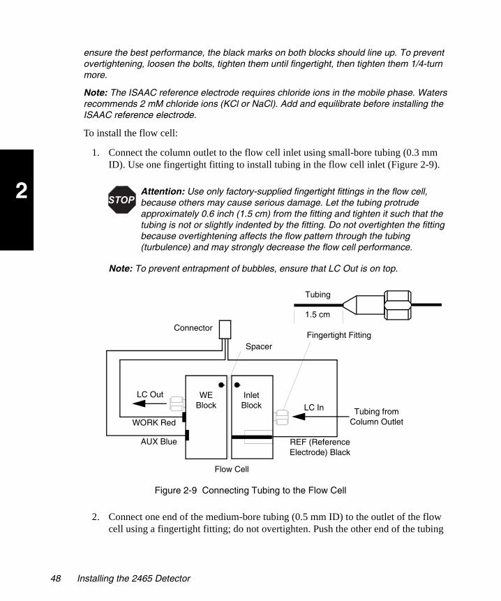
2
2465OG.book Page 48 Wednesday, November 7, 2007 10:33 AM
ensure the best performance, the black marks on both blocks should line up. To prevent overtightening, loosen the bolts, tighten them until fingertight, then tighten them 1/4-turn more.
Note: The ISAAC reference electrode requires chloride ions in the mobile phase. Waters recommends 2 mM chloride ions (KCl or NaCl). Add and equilibrate before installing the ISAAC reference electrode.
To install the flow cell:
1. Connect the column outlet to the flow cell inlet using small-bore tubing (0.3 mm ID). Use one fingertight fitting to install tubing in the flow cell inlet (Figure 2-9).
Note: To prevent entrapment of bubbles, ensure that LC Out is on top.
Figure 2-9 Connecting Tubing to the Flow Cell
2. Connect one end of the medium-bore tubing (0.5 mm ID) to the outlet of the flow cell using a fingertight fitting; do not overtighten. Push the other end of the tubing
Attention: Use only factory-supplied fingertight fittings in the flow cell, because others may cause serious damage. Let the tubing protrude approximately 0.6 inch (1.5 cm) from the fitting and tighten it such that the tubing is not or slightly indented by the fitting. Do not overtighten the fitting because overtightening affects the flow pattern through the tubing (turbulence) and may strongly decrease the flow cell performance.
Connector
LC In
LC Out WE Block
Inlet Block
REF (Reference Electrode) Black
AUX Blue
WORK Red
Spacer
Tubing from Column Outlet
Fingertight Fitting
Flow Cell
1.5 cm
Tubing
48 Installing the 2465 Detector

2
2465OG.book Page 49 Wednesday, November 7, 2007 10:33 AM
through the upper-left hole in the chassis and out to the waste container (Figure 2-10).
Figure 2-10 Installing the Flow Cell
3. Fill the flow cell with mobile phase and install the flow cell in the clamp as follows:
a. Power on the HPLC pump. Keep some tissues nearby in case some mobile phase is spilled.
b. Allow the pump to fill the flow cell by keeping the flow cell at an angle of about 45° with the outlet (LC Out) on top to force the air through the outlet.
c. To prevent trapping of air bubbles, position the flow cell with the reference electrode at the lower side and the outlet at the upper side.
Flow Cell
Column
Flow Cell Cable Connector (9-Pin)
Out to Waste
Fluid In
Flow Cell Outlet (LC Out)
Blue Cable to AUX(Auxiliary Electrode)
Red Cable to WE (Working Electrode)
Black Cable to REF(Reference Electrode)
Outlet Tubing
Making Fluidic Connections 49

2
2465OG.book Page 50 Wednesday, November 7, 2007 10:33 AM
d. Slide the flow cell into the flow cell clamp from the top.
4. Connect the flow cell cable to the flow cell as shown in Figure 2-10. Connect the WE, AUX, and REF on the flow cell using the red, blue, and black cell cable (WE – red, AUX – blue, REF – black).
Note: For electrochemical detection, always use the highest purity buffer salts. Segregate reagents used for electrochemical detection to reduce the likelihood of contamination.
Attention: Avoid using excessive force when installing the flow cell in the clamp by sliding the flow cell downward from above the clamp. Do not press the flow cell into the clamp from the front.
Caution: When you handle solvents, change tubing, or operate the 2465 Detector in general, always observe good laboratory practices. Know the physical and chemical properties of the solvents. Refer to the Material Safety Data Sheets for the solvents in use.
Attention: Before powering on the flow cell, ensure that:
The flow cell is filled with 20 to 100 mM electrolyte (buffer) that contains sufficient electrolyte (buffer ions). A flow cell filled with water is not adequate. A stable baseline will never be obtained if the cell is powered on with only water or another nonconducting mobile phase.
No air bubbles are trapped in the flow cell.
The outlet tubing from the flow cell leads to a waste container that is at a higher level than the flow cell. This ensures a minute backpressure, which prevents air-bubble entrapment. The outlet tubing should be under the liquid level to prevent electrical baseline noise.
Attention: To prevent substantial damage to the working electrode or electronics, never power on the flow cell when:
The cell cable is not correctly connected.
The cell is only partly (or not at all) filled with buffer (not HPLC water).
The outside of the flow cell is wet, particularly the part between the auxiliary and working electrode connection.
Attention: When connecting or disconnecting the flow cell cable, ensure the flow cell power is off (see Section 3.8.1, Turning Off the Flow Cell).
50 Installing the 2465 Detector

2
2465OG.book Page 51 Wednesday, November 7, 2007 10:33 AM
Dedicate glassware to preparation of buffers and mobile phases used for electrochemical detection. Filter the buffer through a 0.22-µm filter before use.
Note: Do not leave the buffer stored in the system after use. Flush all fluidic pathways with HPLC-quality water before shutting the system down and leave HPLC-quality water in the system. Flush with 90% HPLC-quality water:10% methanol for shutdowns scheduled to be more than one day. Use a minimum of 15 mL for sparge-equipped units, and a minimum of 45 mL for inline vacuum degasser-equipped units. Some systems such as Waters Alliance might require volumes lower than this, depending on inline degasser volumes and slow-rate operation limits.
2.5 Making I/O Signal Connections
2.5.1 Rear Panel Connections
The signal connections you need to make to your 2465 Detector (Figure 2-11) depend on:
• The operating mode (stand-alone or remote control)
• The types of instruments in your HPLC system
Caution: To avoid electrical shock, power off the 2465 Detector and unplug the power cord from the rear panel receptacle before you make signal connections or replace a fuse.
Always replace a fuse with the same type and rating, as described on the rear panel.
Attention: Connect the shield to the chassis ground stud. The ground stud is for shielding only, not for safety grounding. To minimize the chance of creating a ground loop that can adversely affect measurement, connect the shield of the cable to the chassis ground at one end only.
Attention: Use shielded cable(s) to connect all I/Os with other devices. Thoroughly connect the shielding to common. Manufacturer will not accept any liability for damage, direct or indirect, caused by connecting this instrument to devices that do not meet the relevant safety standards.
To meet the regulatory requirements of immunity from external electrical disturbances that may affect the performance of this instrument, do not use cables (including RS-232) longer than 9.8 feet (3 meters) when you make connections.
Making I/O Signal Connections 51

2
2465OG.book Page 52 Wednesday, November 7, 2007 10:33 AM
Figure 2-11 Rear Panel Connections on 2465 Detector
The 2465 Detector has several types of event inputs and outputs, relays, and TTL event switches. The 2465 power supply drives the relays. The TTL switches require a minimum pulse of 100-ms duration, low (where low is < 0.8 V). If repetitive activation is required, the next pulse should occur after 100 ms, high (where high is > 2.4 V).
Chassis GroundConnection
Connector A
Connector B
Output to Integrator or SAT/IN (BNC)
RS-232C Connector
Power Switch
Line Connector
Connector CManual Injector
Fuses
52 Installing the 2465 Detector
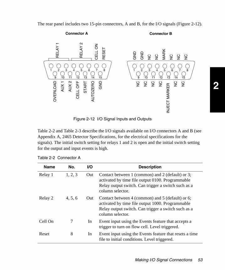
2
2465OG.book Page 53 Wednesday, November 7, 2007 10:33 AM
The rear panel includes two 15-pin connectors, A and B, for the I/O signals (Figure 2-12).
Figure 2-12 I/O Signal Inputs and Outputs
Table 2-2 and Table 2-3 describe the I/O signals available on I/O connectors A and B (see Appendix A, 2465 Detector Specifications, for the electrical specifications for the signals). The initial switch setting for relays 1 and 2 is open and the initial switch setting for the output and input events is high.
Table 2-2 Connector A
Name No. I/O Description
Relay 1 1, 2, 3 Out Contact between 1 (common) and 2 (default) or 3; activated by time file output 0100. Programmable Relay output switch. Can trigger a switch such as a column selector.
Relay 2 4, 5, 6 Out Contact between 4 (common) and 5 (default) or 6; activated by time file output 1000. Programmable Relay output switch. Can trigger a switch such as a column selector.
Cell On 7 In Event input using the Events feature that accepts a trigger to turn on flow cell. Level triggered.
Reset 8 In Event input using the Events feature that resets a time file to initial conditions. Level triggered.
Connector A
RE
LAY
1
RE
LAY
2
CE
LL O
N
RE
SE
T
Connector B
OV
ER
LOA
D
AU
X 1
AU
X 2
CE
LL O
FF
ST
AR
T
AU
TO
ZE
RO
GN
D
GN
D
MA
RK
INJE
CT
MA
RK
ER
GN
D
1 2 3 4 5 6 7 8
159 10 11 12 13 14
1 2 3 4 5 6 7 8
159 10 11 12 13 14
NC
NC
NC
NC
NC
NC
NC
NC
NC
NC
NC
Making I/O Signal Connections 53

2
2465OG.book Page 54 Wednesday, November 7, 2007 10:33 AM
Overload 9 Out Event output switch. Event is triggered when an Out of Range condition (overload) exists. Can trigger a change in flow conditions. When active, output status is low (default is high).
AUX 1 10 Out Free programmable TTL output contact closure. Can activate an external switch, such as a column select valve. Can be triggered in a row in a time file by setting the output parameter to 0001. When active, output status is low (default is high).
AUX 2 11 Out Free programmable TTL output contact closure. Can activate an external switch, such as a column select valve. Can be triggered in a row in a time file by setting the output parameter to 0010. When active, output status is low (default is high).
Cell Off 12 In TTL input contact closure, which turns off the flow cell. Can be connected to a fault switch to shut down flow cell if pumping system loses prime. Level triggered.
Start 13 In TTL input contact closure, which starts a programmed time file. Can be connected to an inject start switch from an autosampler. Level triggered.
Auto Zero 14 In TTL input contact closure, which autozeros the detector. Can be connected to an inject start switch from an autosampler. Always accessible when Ic is on screen. Level triggered
GND or Common
15 Ground
Table 2-3 Connector B
Name No. I/O Description
GND or Common
1, 2 Ground
N/C 3, 4, 6 – 12, 14, 15
Not connected
Table 2-2 Connector A (Continued)
Name No. I/O Description
54 Installing the 2465 Detector

2
2465OG.book Page 55 Wednesday, November 7, 2007 10:33 AM
The 2465 Detector can send output signals to an integrator or a Waters SAT/IN Module using a standard BNC connector for the analog output (see Output, Figure 2-11). Table 2-4 shows the signals for the Output connector.
2.5.2 Connecting to a 2695 Separations Module (Stand-Alone)
You can connect the 2465 Detector to the Waters 2695 Separations Module, when it is not under the control of the Empower software, to perform the following:
• Autozero on inject start
• Chart mark on inject start
• Start a method on inject start
• Turn flow cell off
Generating Autozero on Inject Start
To autozero the 2465 Detector at the start of an injection, make the following connections (see Figure 2-13):
MARK (Input)
5 In Level triggered, TTL contact closure. Accepts input after 100 ms. When activated, makes a baseline spike of 10% FS, 100 ms (0.1 s) duration.
INJECT MARKER
13 Out Use with manual injector. Load = high, Inject = low.
Table 2-4 Output (+1 V or +10 V)
No. Polarity Description
1 Positive To integrator or A/D device.
2 Negative
2695 Separations Module (B Inputs and Outputs)
2465 Detector(Connector A Inputs)
Pin 1 Inject Start Pin 14 Auto Zero +Pin 2 Inject Start Pin 15 Ground –
Table 2-3 Connector B (Continued)
Name No. I/O Description
Making I/O Signal Connections 55

2
2465OG.book Page 56 Wednesday, November 7, 2007 10:33 AM
Figure 2-13 2695 Separations Module Connections to the 2465 Detector
Generating a Chart Mark on Inject Start
To generate the chart mark function on the 2465 Detector at the start of an injection, make the following connections:
Starting a Method on Inject Start
To start a method on the 2465 Detector at the start of an injection from a 2695 Separations Module, make the following connections:
2695 Separations Module (B Inputs and Outputs)
2465 Detector(Connector B Inputs)
Pin 1 Inject Start Pin 5 Chart Mark +Pin 2 Inject Start Pin 1 or 2 Ground –
2695 Separations Module (B Inputs and Outputs)
2465 Detector(Connector B Inputs)
Pin 1 Inject Start Pin 13 Method Start +Pin 2 Inject Start Pin 15 Ground –
Waters 2465Connector A (Inputs)
Waters 2695B (Inputs and Outputs)
1
2
3
4
5
6
7
8
9
10
11
12
Inject Start
Inject start
Ground
Stop Flow +
Stop Flow
Hold Inject 1 +
Hold Inject 1
Hold Inject 2 +
Hold Inject 2
Ground
Chart Out +
Chart Out
RE
LAY
1
RE
LAY
2
CE
LL O
N
RE
SE
T
OV
ER
LOA
D
AU
X 1
AU
X 2
CE
LL O
FF
ST
AR
T
AU
TO
ZE
RO
GN
D
1 2 3 4 5 6 7 8
159 10 11 12 13 14
56 Installing the 2465 Detector

2
2465OG.book Page 57 Wednesday, November 7, 2007 10:33 AM
Turning Off the Flow Cell
To turn off the flow cell when the flow has stopped, make the following connections:
2.5.3 Connecting to a busSAT/IN Module
You can perform data acquisition from the 2465 Detector with Millennium®32 4.0 software using the busSAT/IN Module. The following hardware must be connected:
• Laboratory acquisition and control environment (LAC/E™) module (LAC/E32 Acquisition Server or busLAC/E card)
• Satellite interface (SAT/IN) module (Figure 2-14)
Figure 2-14 busSAT/IN Module (Front Panel)
The Waters busSAT/IN Module translates analog signals from devices such as the 2465 Detector into digital form, then transmits the digital signals to the busLAC/E or LAC/E32 card installed in the Millennium32 workstation.
2695 Separations Module (B Inputs and Outputs)
2465 Detector(Connector A Inputs)
Pin 4 Pin 12 Cell Off +Pin 5 Pin 15 Ground –
TP01138
Waters Bus SAT/IN Module
CHANNEL 1 CHANNEL 2IN OUT IN OUT
EVENTSCH1 CH 2
CH1 CH2 OK
Making I/O Signal Connections 57
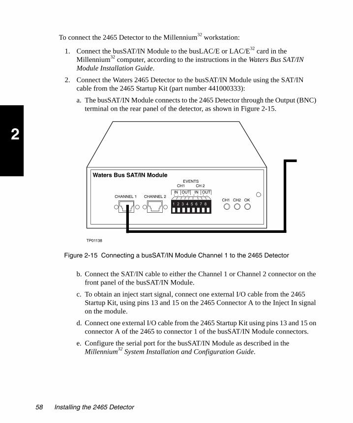
2
2465OG.book Page 58 Wednesday, November 7, 2007 10:33 AM
To connect the 2465 Detector to the Millennium32 workstation:
1. Connect the busSAT/IN Module to the busLAC/E or LAC/E32 card in the Millennium32 computer, according to the instructions in the Waters Bus SAT/IN Module Installation Guide.
2. Connect the Waters 2465 Detector to the busSAT/IN Module using the SAT/IN cable from the 2465 Startup Kit (part number 441000333):
a. The busSAT/IN Module connects to the 2465 Detector through the Output (BNC) terminal on the rear panel of the detector, as shown in Figure 2-15.
Figure 2-15 Connecting a busSAT/IN Module Channel 1 to the 2465 Detector
b. Connect the SAT/IN cable to either the Channel 1 or Channel 2 connector on the front panel of the busSAT/IN Module.
c. To obtain an inject start signal, connect one external I/O cable from the 2465 Startup Kit, using pins 13 and 15 on the 2465 Connector A to the Inject In signal on the module.
d. Connect one external I/O cable from the 2465 Startup Kit using pins 13 and 15 on connector A of the 2465 to connector 1 of the busSAT/IN Module connectors.
e. Configure the serial port for the busSAT/IN Module as described in the Millennium32 System Installation and Configuration Guide.
TP01138
Waters Bus SAT/IN Module
CHANNEL 1 CHANNEL 2IN OUT IN OUT
EVENTSCH1 CH 2
CH1 CH2 OK
58 Installing the 2465 Detector
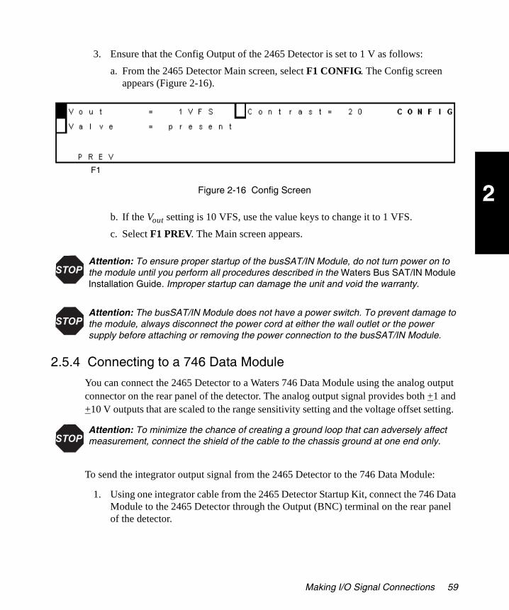
2
2465OG.book Page 59 Wednesday, November 7, 2007 10:33 AM
3. Ensure that the Config Output of the 2465 Detector is set to 1 V as follows:
a. From the 2465 Detector Main screen, select F1 CONFIG. The Config screen appears (Figure 2-16).
Figure 2-16 Config Screen
b. If the Vout setting is 10 VFS, use the value keys to change it to 1 VFS.
c. Select F1 PREV. The Main screen appears.
2.5.4 Connecting to a 746 Data Module
You can connect the 2465 Detector to a Waters 746 Data Module using the analog output connector on the rear panel of the detector. The analog output signal provides both +1 and +10 V outputs that are scaled to the range sensitivity setting and the voltage offset setting.
To send the integrator output signal from the 2465 Detector to the 746 Data Module:
1. Using one integrator cable from the 2465 Detector Startup Kit, connect the 746 Data Module to the 2465 Detector through the Output (BNC) terminal on the rear panel of the detector.
Attention: To ensure proper startup of the busSAT/IN Module, do not turn power on to the module until you perform all procedures described in the Waters Bus SAT/IN Module Installation Guide. Improper startup can damage the unit and void the warranty.
Attention: The busSAT/IN Module does not have a power switch. To prevent damage to the module, always disconnect the power cord at either the wall outlet or the power supply before attaching or removing the power connection to the busSAT/IN Module.
Attention: To minimize the chance of creating a ground loop that can adversely affect measurement, connect the shield of the cable to the chassis ground at one end only.
F1
Making I/O Signal Connections 59

2
2465OG.book Page 60 Wednesday, November 7, 2007 10:33 AM
2. Ensure that the Config Output of the 2465 Detector is set to 1 V as follows:
a. From the 2465 Detector Main screen, select F1 CONFIG. The Config screen appears (Figure 2-16).
b. If the Vout setting is 10 VFS, use the value keys to change it to 1 VFS.
c. Select F1 PREV. The Main screen appears.
2.5.5 Making RS-232 Connections
The rear panel includes one RS-232 interface connector for digital signal communications. Use the RS-232 interface connector to connect the 2465 Detector to RS-232 devices, such as an RS-232 communications port in an Empower Personal, Workgroup PC, or Enterprise client configuration. The RS-232 connector uses a standard RS-232 cable, which is provided in the 2465 Detector Startup Kit.
Note: When you connect the RS-232 cable and establish communications, the 2465 Detector operates in remote mode (see Section 3.2.4, Remote Mode).
To connect the 2465 Detector to a Waters data system:
1. Connect the single receptacle end of the RS-232 cable to an RS-232 device, such as an RS-232 communications port or Equinox card in an Empower system.
2. Connect the other end of the cable to the RS-232 connector on the 2465 Detector rear panel.
3. Ensure all RS-232 cable screws are fastened tightly.
4. Ensure all input/output connections are correct, as in the example diagram in Figure 2-17.
Attention: To prevent oversaturation of the signal from the 2465 Detector to the 746 Data Module, do not exceed the input voltage rating of the 746 Data Module. At the 2465 Detector, either change the range or maximize the compensation as offset.
Attention: To avoid possible damage to components, power off all instruments on the RS-232 control bus before you connect an RS-232 interface cable to an instrument.
Attention: The maximum total cable length between RS-232 devices in a system is 65 feet (20 meters). The maximum recommended cable length between two RS-232 devices is 10 feet (3 meters). Longer total cable lengths can cause intermittent RS-232 communication failures.
60 Installing the 2465 Detector
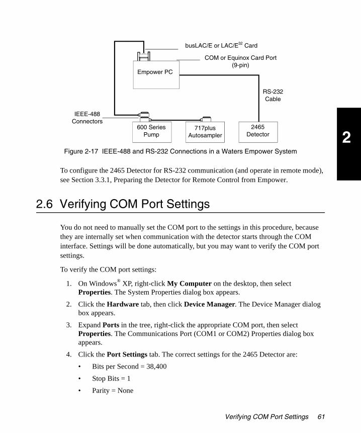
2
2465OG.book Page 61 Wednesday, November 7, 2007 10:33 AM
Figure 2-17 IEEE-488 and RS-232 Connections in a Waters Empower System
To configure the 2465 Detector for RS-232 communication (and operate in remote mode), see Section 3.3.1, Preparing the Detector for Remote Control from Empower.
2.6 Verifying COM Port Settings
You do not need to manually set the COM port to the settings in this procedure, because they are internally set when communication with the detector starts through the COM interface. Settings will be done automatically, but you may want to verify the COM port settings.
To verify the COM port settings:
1. On Windows® XP, right-click My Computer on the desktop, then select Properties. The System Properties dialog box appears.
2. Click the Hardware tab, then click Device Manager. The Device Manager dialog box appears.
3. Expand Ports in the tree, right-click the appropriate COM port, then select Properties. The Communications Port (COM1 or COM2) Properties dialog box appears.
4. Click the Port Settings tab. The correct settings for the 2465 Detector are:
• Bits per Second = 38,400
• Stop Bits = 1
• Parity = None
RS-232 Cable
busLAC/E or LAC/E32 Card
COM or Equinox Card Port(9-pin)
Empower PC
600 Series Pump
717plus Autosampler
2465 Detector
IEEE-488 Connectors
Verifying COM Port Settings 61

2
2465OG.book Page 62 Wednesday, November 7, 2007 10:33 AM
• Data Length = 8
• Flow Control = None
5. Click OK.
6. Close the dialog boxes (Device Manager, System Properties, and other dialog boxes).
62 Installing the 2465 Detector
3
2465OG.book Page 63 Wednesday, November 7, 2007 10:33 AM
Chapter 3 Operating the 2465 Detector
After you have installed the Waters 2465 Electrochemical Detector (see Chapter 2, Installing the 2465 Detector), it is ready to set up and operate either:
• As a stand-alone electrochemical detector with a system such as the Alliance® system or with a pump, autosampler, chart recorder, or integrator
• In remote mode using Empower software or other data system software
Note: To ensure accurate operation, and before pumping any mobile phase, solvent, buffer, or electrolyte through the flow cell, be sure to perform the procedures in Section 3.1, Starting Up the Detector.
3.1 Starting Up the Detector
3.1.1 Powering On the Detector
Before you power on the 2465 Detector, ensure the power cord is properly installed from the detector rear panel to the power source (see Section 2.3, Making Electrical Power Connections).
Note: The 2465 Detector does not have any audible alarms, bells, or beeps.
To start up the 2465 Detector:
1. Power on the 2465 Detector by pressing the power switch on the rear panel of the detector (see Figure 2-11). The detector runs several diagnostic tests and displays a message (Figure 3-1).
Attention: Do not turn on the flow cell until it is prepared properly (see Section 3.4.2, Section 3.5.5, or Section 3.6.2).
Starting Up the Detector 63

3
2465OG.book Page 64 Wednesday, November 7, 2007 10:33 AM
Figure 3-1 Calculating Checksum Screen
2. If an error message appears, contact Waters Technical Service (see Section 4.1.4).
If the detector passes the diagnostic tests, an eight-digit checksum appears (Figure 3-2).
Note: The correct checksum for your firmware version is in the Release Notes.
Figure 3-2 Checksum Screen
After a few seconds, the Main screen appears (Figure 3-3).
• The name of the detector is in row 1.
• The firmware version is in row 3.
• The five function keys are in row 4 (see Section 3.1.5, Using the Function Keys).
Figure 3-3 Main Screen
3.1.2 Using the Display
This section describes how to use the display and the keypad on the front panel of the 2465 Detector. All messages and screens appear on a 4 × 40 liquid crystal display (LCD).
F1 F2 F3 F4 F5
64 Operating the 2465 Detector
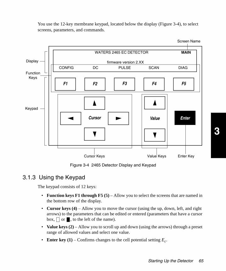
3
2465OG.book Page 65 Wednesday, November 7, 2007 10:33 AM
You use the 12-key membrane keypad, located below the display (Figure 3-4), to select screens, parameters, and commands.
Figure 3-4 2465 Detector Display and Keypad
3.1.3 Using the Keypad
The keypad consists of 12 keys:
• Function keys F1 through F5 (5) – Allow you to select the screens that are named in the bottom row of the display.
• Cursor keys (4) – Allow you to move the cursor (using the up, down, left, and right arrows) to the parameters that can be edited or entered (parameters that have a cursor box, or , to the left of the name).
• Value keys (2) – Allow you to scroll up and down (using the arrows) through a preset range of allowed values and select one value.
• Enter key (1) – Confirms changes to the cell potential setting Ec.
Cursor Value
F1 F2 F3 F4 F5
Enter
Function Keys
Cursor Keys
Screen Name
Keypad
Display
Value Keys Enter Key
CONFIG DC PULSE SCAN DIAG
MAINWATERS 2465 EC DETECTOR
firmware version 2.XX
Starting Up the Detector 65

3
2465OG.book Page 66 Wednesday, November 7, 2007 10:33 AM
3.1.4 Finding the Parameters
Three types of parameters can appear on each screen:
• Function – Parameters on the bottom row of the display and in capital letters are commands that you can access using function keys F1 through F5. Table 3-2 describes the commands in alphabetical order with screen location(s) and descriptions (see Section 3.1.7, Function Key Commands).
• Control – You can move to any parameter with a cursor box using the four cursor keys. Table 3-5 describes the control parameters in alphabetical order with screen location(s), descriptions, and type.
– Cursor box is selected. When the cursor box is solid, you can change the parameter using the plus and minus value keys.
– Cursor box is not selected.
• Status – A parameter without a cursor box displays the current status or value of the parameter. You cannot edit a status parameter. Table 3-5 describes the status parameters in alphabetical order with screen location(s), descriptions, and type.
3.1.5 Using the Function Keys
The top row of keys on the keypad, F1 through F5, correspond to the bottom row of the display. These are function keys, and they have variable commands that change with the screen. The commands for the function keys are capitalized. For example, in Figure 3-4, pressing function key F4 SCAN accesses the Scan Setup screen.
The function keys on the Main screen access the following:
• F1 – Config (Configuration) screen
• F2 – DC Setup screen (see Section 3.2.1, DC Mode)
• F3 – Pulse Setup1 screen (see Section 3.2.2, Pulse (PAD) Mode)
• F4 – Scan Setup screen (see Section 3.2.3, Scan Mode)
• F5 – Diag (Diagnostics) screen for the diagnostic tests (see Chapter 5, Diagnostics and Troubleshooting)
66 Operating the 2465 Detector
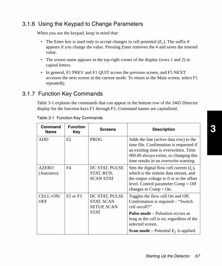
3
2465OG.book Page 67 Wednesday, November 7, 2007 10:33 AM
3.1.6 Using the Keypad to Change Parameters
When you use the keypad, keep in mind that:
• The Enter key is used only to accept changes in cell potential (Ec). The suffix # appears if you change the value. Pressing Enter removes the # and saves the entered value.
• The screen name appears in the top-right corner of the display (rows 1 and 2) in capital letters.
• In general, F1 PREV and F1 QUIT access the previous screen, and F5 NEXT accesses the next screen in the current mode. To return to the Main screen, select F1 repeatedly.
3.1.7 Function Key Commands
Table 3-1 explains the commands that can appear in the bottom row of the 2465 Detector display for the function keys F1 through F5. Command names are capitalized.
Table 3-1 Function Key Commands
Command Name
Function Key
Screens Description
ADD F2 PROG Adds the line (active data row) to the time file. Confirmation is requested if an existing time is overwritten. Time 000.00 always exists, so changing this time results in an overwrite warning.
AZERO (Autozero)
F4 DC STAT, PULSE STAT, RUN, SCAN STAT
Sets the digital flow cell current (Ic), which is the remote data stream, and the output voltage to 0 or to the offset level. Control parameter Comp = Off changes to Comp = On.
CELL=ON/ OFF
F2 or F3 DC STAT, PULSE STAT, SCAN SETUP, SCAN STAT
Toggles the flow cell On and Off. Confirmation is required – “Switch cell on/off?”
Pulse mode – Pulsation occurs as long as the cell is on, regardless of the selected screen.
Scan mode – Potential E1 is applied.
Starting Up the Detector 67

3
2465OG.book Page 68 Wednesday, November 7, 2007 10:33 AM
CONFIG F1 MAIN Accesses the Config screen:
• To change the display contrast
• To change the voltage output
DC F2 MAIN Accesses the DC Setup screen in DC mode.
DEL (Delete)
F3 PROG Deletes the current line from the time file. Deleting time 000.00 deletes all entries in the time file, and confirmation is required.
DIAG (Diagnostics)
F5 MAIN Accesses the Diag screen for performing the diagnostic tests (see Section 5.2, Diagnostics).
DISPL (Display)
F4 DIAG Accesses the Disp (Display) screen for testing the display (see Section 5.2.4, Display Test).
ENDCYCLE F5 PROG Enters a screen for setting the end cycle time, which controls duration of the time file. When this time is reached, execution of the time file stops. If programmed, the next run is started. Allowed values: 0.01 to 999.99 minutes; cannot be smaller than smallest time in the time file plus 0.01 minute. Default value: 0.01 minute.
EVENTS F4 DC SETUP, PULSE SETUP2
Accesses the Events Setup screen.
HOLD/ RESUME
F2 or F5 RUN, SCAN STAT Toggles between holding and resuming the execution of a time file or scan.
KEYB (Keyboard)
F3 DIAG Accesses the Keyb (Keyboard) screen for testing the keypad.
Table 3-1 Function Key Commands (Continued)
Command Name
Function Key
Screens Description
68 Operating the 2465 Detector

3
2465OG.book Page 69 Wednesday, November 7, 2007 10:33 AM
MARK F3 DC STAT, PULSE STAT
Triggers a marker signal (chart mark) on output (baseline spike of 10% FS, 100 ms duration).
NEXT F1 or F5 Several screens Accesses a related screen in the current mode.
NO F4 Several screens Negates a requested change to a parameter, then returns to the previous screen. Select No if you first make a change to a parameter, then decide not to change it.
NOISE F2 DIAG Accesses the Noise screen and starts the noise performance test (see Section 5.2.4, Display Test).
POLAR= +/– (Polarity)
F3 DC SETUP, PULSE SETUP2, PROG
Inverts output polarity; toggles between + and –. Change requires confirmation. Affects both digital and analog data.
PREV (Previous)
F1 Many screens Returns to the previous screen.
PULSE F3 MAIN Accesses the Pulse Setup1 screen in pulse mode.
QUIT F1 RUN Stops the time file, returns to the Events Setup screen, and resets the cycle counter (Cyc) to 1. Also resets Outputs Aux 1 and 2, and Relays 1 and 2 (status: 0000).
RUN F3 EVENTS SETUP Accesses the Run screen, and waits for the Start input trigger (external or keypad) to start a run.
SCAN F4 MAIN Accesses the Scan Setup screen in scan mode.
SCROLL F4 PROG Scrolls through a time file, one line at a time.
Table 3-1 Function Key Commands (Continued)
Command Name
Function Key
Screens Description
Starting Up the Detector 69

3
2465OG.book Page 70 Wednesday, November 7, 2007 10:33 AM
3.1.8 Status and Control Parameters
You can change active control parameters using the cursor and value keys (see Section 3.1.3, Using the Keypad). Table 3-2 explains the status and control parameters that appear on the 2465 Detector screens, primarily in the top three rows of the display.
START F2 or F3 RUN, SCAN STAT DC and pulse modes – Toggles between Stop and Start to control execution of a time file.
Scan mode – Starts a scan.
STOP F2 or F3 RUN, SCAN STAT DC and pulse modes – Toggles between Stop and Start to control execution of a time file. Selecting Stop aborts the run, resets the cycle counter (Cyc) to 1, and deactivates the outputs Aux 1 and 2 and Relays 1 and 2 (status: 0000).
Scan mode – Stops the scan and resets the cell potential to E1.
YES F2 Several screens Confirms that you want to change a parameter, then returns to the previous screen.
Table 3-2 Status and Control Parameters
Parameter Name
Screens Description Type
28 > 30oC DC STAT, PULSE STAT, RUN, SCAN STAT, REMOTE (DC, PULSE, SCAN)
Displays the actual temperature (left value) and the temperature setting (right value) of the detector oven.
Status
Azero PROG Controls Autozero, which can be programmed in a time file. Toggles between Set and Not.
Control
Table 3-1 Function Key Commands (Continued)
Command Name
Function Key
Screens Description
70 Operating the 2465 Detector

3
2465OG.book Page 71 Wednesday, November 7, 2007 10:33 AM
COMP (Compen- sation)
DC STAT, PULSE STAT, REMOTE (DC, PULSE, SCAN)
Toggles between on and off, and releases the Azero offset. Switches on if Azero is selected. Affects Azero compensation only, not the % offset.
Control
Contrast CONFIG Changes the contrast of the display. Allowed values: 1 (lightest) to 20 (darkest). Default: 20.
Control
Cyc (Cycle) RUN Displays the cycle counter. If a time file has to be executed more than once (Cycles > 1), this parameter counts the number of times a time file has been started. Reset (external) or F1 QUIT sets Cyc to 1 and the Events Setup screen appears. F3 STOP aborts the cycle.
Status
SCAN SETUP (control), SCAN STAT (status)
Controls the length of each cycle:
• Cyc=half – The cell potential runs from E1 to E2 and jumps back to E1.
• Cyc=full – The cell potential runs from E1 to E2, back to E1, then stops.
• Cyc=cont – The cell potential runs continuously from E1 to E2 and back to E1.
Selecting F2 STOP or finishing the cycle (for half or full) sets the potential to E1.
Control
Cycles EVENTS SETUP Controls the number of repeats of a time file. Allowed values: 1 to 999 or cont (continuous).
Control
E1, E2, E3 PULSE SETUP2, REMOTE PULSE
Controls the cell potential settings of the pulse.
Control
Table 3-2 Status and Control Parameters (Continued)
Parameter Name
Screens Description Type
Starting Up the Detector 71
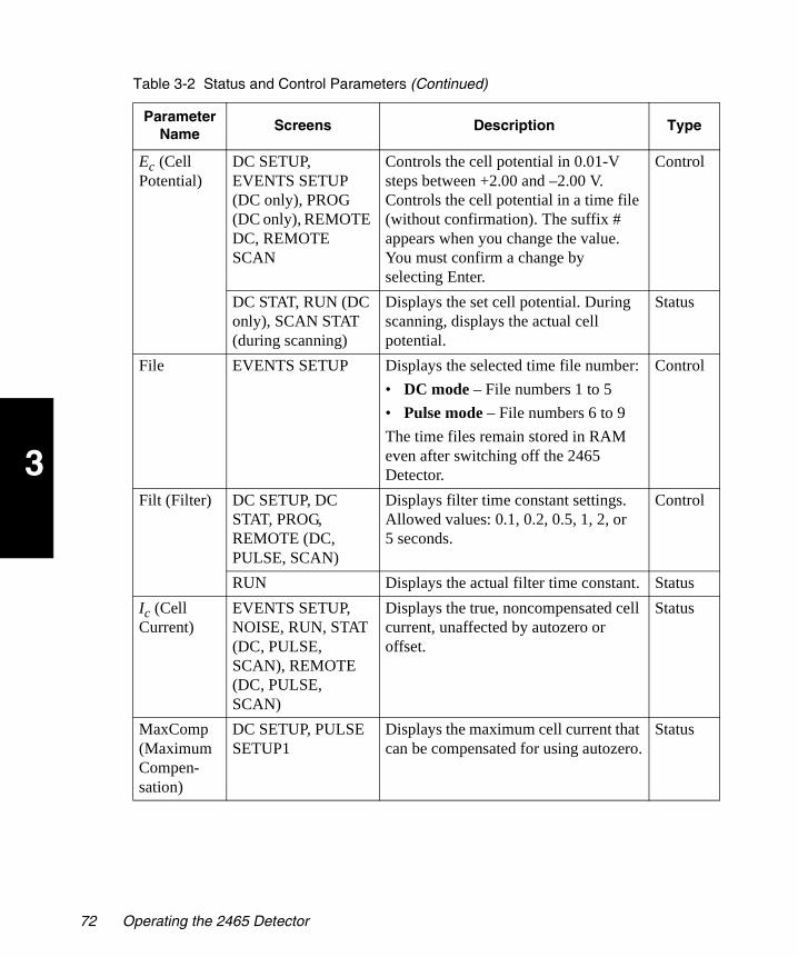
3
2465OG.book Page 72 Wednesday, November 7, 2007 10:33 AM
Ec (Cell Potential)
DC SETUP, EVENTS SETUP (DC only), PROG (DC only), REMOTE DC, REMOTE SCAN
Controls the cell potential in 0.01-V steps between +2.00 and –2.00 V. Controls the cell potential in a time file (without confirmation). The suffix # appears when you change the value. You must confirm a change by selecting Enter.
Control
DC STAT, RUN (DC only), SCAN STAT (during scanning)
Displays the set cell potential. During scanning, displays the actual cell potential.
Status
File EVENTS SETUP Displays the selected time file number:
• DC mode – File numbers 1 to 5
• Pulse mode – File numbers 6 to 9
The time files remain stored in RAM even after switching off the 2465 Detector.
Control
Filt (Filter) DC SETUP, DC STAT, PROG, REMOTE (DC, PULSE, SCAN)
Displays filter time constant settings. Allowed values: 0.1, 0.2, 0.5, 1, 2, or 5 seconds.
Control
RUN Displays the actual filter time constant. Status
Ic (Cell Current)
EVENTS SETUP, NOISE, RUN, STAT (DC, PULSE, SCAN), REMOTE (DC, PULSE, SCAN)
Displays the true, noncompensated cell current, unaffected by autozero or offset.
Status
MaxComp (Maximum Compen- sation)
DC SETUP, PULSE SETUP1
Displays the maximum cell current that can be compensated for using autozero.
Status
Table 3-2 Status and Control Parameters (Continued)
Parameter Name
Screens Description Type
72 Operating the 2465 Detector

3
2465OG.book Page 73 Wednesday, November 7, 2007 10:33 AM
Offs (Offset)
DC SETUP, DC STAT, PROG, PULSE SETUP1, PULSE STAT, SCAN SETUP, SCAN STAT
Controls or displays the percentage offset. Allowed values: –50% to +50% in 5% steps.
Control
RUN Displays the percentage offset during execution of a time file.
Status
Outp (Output)
PROG Controls four output functions in time files:
• 0 – Open/high
• 1 – Closed/low
AUX1: 0001, AUX2: 0010, RELAY 1: 0100, RELAY 2: 1000. Combinations are possible (for example, enter 0101 to change the status of AUX1 to Low and RELAY1 to Closed at the same time).
Control
Range DC SETUP, DC STAT, PROG, PULSE SETUP1, PULSE STAT, SCAN SETUP, SCAN STAT, REMOTE (DC, PULSE, SCAN)
Displays the range setting. Allowed values in DC mode: 10 pA to 200 µA full scale, in 1, 2, or 5 steps.
Allowed values in pulse and scan modes: 10 nA to 200 µA full scale, in 1, 2, or 5 steps.
Control
SPD (Speed)
SCAN SETUP Controls the scan speed. Allowed values: 1 to 50 mV/s in 1, 2, or 5 steps.
Control
t (Time) PULSE SETUP2, PULSE STAT
Displays the total duration of one pulse (t1 + t2 + t3) in ms.
Status
t1, t2, t3 PULSE SETUP2 Controls the duration of potential steps E1, E2, or E3. Allowed values: 0 (t2, t3) or 100 (t1) and 2000 ms in 10-ms steps.
Control
Table 3-2 Status and Control Parameters (Continued)
Parameter Name
Screens Description Type
Starting Up the Detector 73
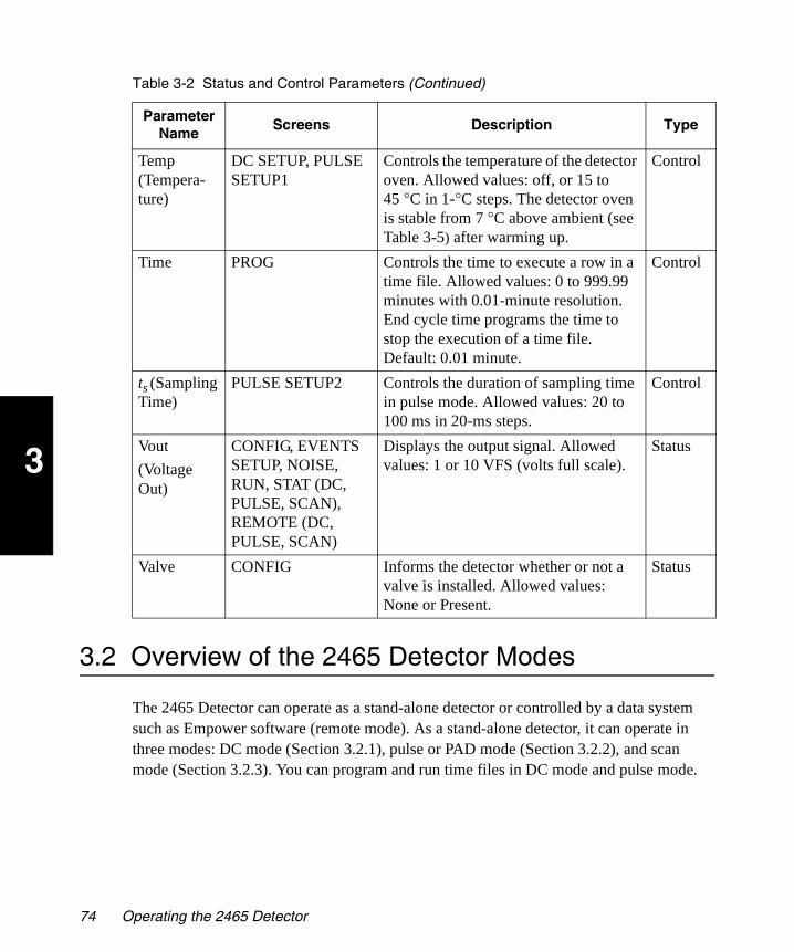
3
2465OG.book Page 74 Wednesday, November 7, 2007 10:33 AM
3.2 Overview of the 2465 Detector Modes
The 2465 Detector can operate as a stand-alone detector or controlled by a data system such as Empower software (remote mode). As a stand-alone detector, it can operate in three modes: DC mode (Section 3.2.1), pulse or PAD mode (Section 3.2.2), and scan mode (Section 3.2.3). You can program and run time files in DC mode and pulse mode.
Temp (Tempera- ture)
DC SETUP, PULSE SETUP1
Controls the temperature of the detector oven. Allowed values: off, or 15 to 45 °C in 1-°C steps. The detector oven is stable from 7 °C above ambient (see Table 3-5) after warming up.
Control
Time PROG Controls the time to execute a row in a time file. Allowed values: 0 to 999.99 minutes with 0.01-minute resolution. End cycle time programs the time to stop the execution of a time file. Default: 0.01 minute.
Control
ts (Sampling Time)
PULSE SETUP2 Controls the duration of sampling time in pulse mode. Allowed values: 20 to 100 ms in 20-ms steps.
Control
Vout
(Voltage Out)
CONFIG, EVENTS SETUP, NOISE, RUN, STAT (DC, PULSE, SCAN), REMOTE (DC, PULSE, SCAN)
Displays the output signal. Allowed values: 1 or 10 VFS (volts full scale).
Status
Valve CONFIG Informs the detector whether or not a valve is installed. Allowed values: None or Present.
Status
Table 3-2 Status and Control Parameters (Continued)
Parameter Name
Screens Description Type
74 Operating the 2465 Detector

3
2465OG.book Page 75 Wednesday, November 7, 2007 10:33 AM
3.2.1 DC Mode
You can use DC mode (as a stand-alone detector) to:
• Stabilize the detector.
• Determine if a compound is electrochemically active.
• Optimize sample detection by constructing a voltammogram.
• Determine the optimum start and stop times of a sample.
You can test samples directly, or program and run a time file in DC mode (see Section 3.4, Using DC Mode). Figure 3-5 shows a typical navigation flow in DC mode.
Figure 3-5 DC Mode Navigation
MAIN
F2 (DC)
F5 (NEXT)F2 (CELL= ON/OFF)
Change Polarity? YES or NO
Switch Cell On/Off?
YES or NO
F1 (PREV)
F3 (POLAR)
F3 (RUN)
F5 (NEXT)
See B on Next Page
See A on Next Page
DC SETUP
DC STATEVENTS SETUP
F4 (EVENTS)
Overview of the 2465 Detector Modes 75

3
2465OG.book Page 76 Wednesday, November 7, 2007 10:33 AM
Figure 3-5 DC Mode Navigation (Continued)
F1 (QUIT)
F2 (HOLD)
F3 (START)
A (From Previous
Page)EVENTS SETUP
F4 (AZERO)
F1 (QUIT)
F2 (RESUME)
AUTOZERO
AUTOZERO
F4 (AZERO)
F3 (STOP)
F1 (PREV)
B (From Previous
Page)EVENTS SETUP
F5 (ENDCYCLE)
F1 (PREV)
ENDCYCLE
F3 (DEL)
F4 (SCROLL)
Delete Time=nnn.nn?
YES or NO
Overwrite Time=nnn.nn?
YES or NORUN
(Running)
RUN(Holding)
F4 (SCROLL)
F2 (ADD)
RUN(Waiting)
PROG nnn.nn
TIME FILELINE nnn.nn
76 Operating the 2465 Detector
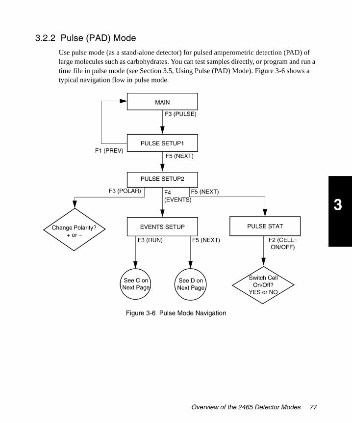
3
2465OG.book Page 77 Wednesday, November 7, 2007 10:33 AM
3.2.2 Pulse (PAD) Mode
Use pulse mode (as a stand-alone detector) for pulsed amperometric detection (PAD) of large molecules such as carbohydrates. You can test samples directly, or program and run a time file in pulse mode (see Section 3.5, Using Pulse (PAD) Mode). Figure 3-6 shows a typical navigation flow in pulse mode.
Figure 3-6 Pulse Mode Navigation
MAIN
F3 (PULSE)
F1 (PREV)PULSE SETUP1
F4 (EVENTS)
F5 (NEXT) F2 (CELL= ON/OFF)
Change Polarity? + or
PULSE STATEVENTS SETUP
F3 (POLAR)
F3 (RUN)
F5 (NEXT)
F5 (NEXT)
Switch Cell On/Off?
YES or NO
See D on Next Page
See C on Next Page
PULSE SETUP2
Overview of the 2465 Detector Modes 77

3
2465OG.book Page 78 Wednesday, November 7, 2007 10:33 AM
Figure 3-6 Pulse Mode Navigation (Continued)
F1 (QUIT)
F2 (HOLD)
F3 (START)
C (From Previous
Page)EVENTS SETUP
F4 (AZERO)
F1 (QUIT)
F2 (RESUME)
AUTOZERO
AUTOZERO
F4 (AZERO)
F3 (STOP)
F1 (PREV)
D (From Previous
Page)EVENTS SETUP
F5 (ENDCYCLE)
F1 (PREV)
ENDCYCLE
F3 (DEL)
F4 (SCROLL)
Delete Time=nnn.nn?
YES or NO
Overwrite Time=nnn.nn?
YES or NORUN
(Running)
RUN(Holding)
F4 (SCROLL)
F2 (ADD)
RUN(Waiting)
PROG nnn.nn
TIME FILELINE nnn.nn
78 Operating the 2465 Detector

3
2465OG.book Page 79 Wednesday, November 7, 2007 10:33 AM
3.2.3 Scan Mode
You can use scan mode (as a stand-alone detector) for developing a method. You can test samples directly in scan mode (see Section 3.6, Using Scan Mode). However, you cannot program and run time files in scan mode. Figure 3-7 shows a typical navigation flow in scan mode.
Figure 3-7 Scan Mode Navigation
3.2.4 Remote Mode
The 2465 Detector operates in remote mode when samples are run under the control of an external data system such as Empower software, and an Empower method is setting up and/or running. The 2465 Detector operates in remote mode from the instant that the setup method starts until the time a run ends or is aborted. Remote mode occurs when Empower is setting up a run or actively collecting data from the 2465 Detector. During remote mode, the word “Remote” appears as the title in the upper-right corner of the 2465 display (Figure 3-8 through Figure 3-10).
F4 (SCAN)
F3 (STOP)Switch Cell
On/Off?YES or NO
SCAN STAT(Waiting)
F1 (PREV)
F3 (CELL= ON/OFF)F5 (NEXT)
F5 (HOLD)
MAIN
SCAN SETUP
SCAN STAT(Running)
SCAN STAT(Holding)
F3 (START)
F3 (CELL= ON/OFF)
F5 (RESUME)
Overview of the 2465 Detector Modes 79

3
2465OG.book Page 80 Wednesday, November 7, 2007 10:33 AM
Figure 3-8 Remote DC Mode
Figure 3-9 Remote Pulse Mode
Figure 3-10 Remote Scan Mode
When an Empower run is in process, remote mode prevents any use of the front panel keypad of the 2465 Detector. The status parameters are updated during the run.
The front panel keypad of the 2465 Detector is available whenever Empower is not setting up a method or performing a run.
Under Empower control, the 2465 Detector uses the RS-232 connector (Section 2.5.5, Making RS-232 Connections). To connect the 2465 Detector to your HPLC system, see Section 2.4, Making Fluidic Connections. To make signal connections to an external system, see Section 2.5, Making I/O Signal Connections.
Note: Parameter settings and some time programmable functions are different in the stand-alone mode and the remote mode (using Empower software).
F1
F1
F1
80 Operating the 2465 Detector

3
2465OG.book Page 81 Wednesday, November 7, 2007 10:33 AM
3.2.5 Introduction to Time Files
The Events feature of the 2465 Detector enables a time-based, automated control of electrochemical detection. Time files can be programmed and saved in stand-alone mode (not remotely controlled by Empower software; see Section 3.4.3, Creating a Time File in DC Mode, and Section 3.5.6, Creating a Time File in Pulse Mode). Time files are particularly useful for changing settings (such as sensitivity or autozero), for controlling external equipment (for example, a trigger to start integration software), or for changing the potential to optimize each peak in a chromatogram.
A time file contains a series of lines (or rows) in which you can change the events (settings of the 2465 Detector) with a time resolution of 0.01 minute (0.6 second). Time files 1 through 5 are reserved for DC mode, and time files 6 through 9 are reserved for pulse mode.
You create (or program) a time file using the Prog screen, then run a time file using the Events Setup screen. Time files are saved even if the 2465 Detector is powered off.
Note: You cannot create or run time files in scan mode.
Programmable Parameters in Time Files
The following programmable parameters can control the status of external equipment using the 2465 Detector output contacts (see Table 3-2, Status and Control Parameters, and Section 2.5, Making I/O Signal Connections):
• Cell potential (Ec in DC mode, and E1, E2, and E3 in pulse mode)
• Range
• Autozero (Azero)
• Offset (Offs)
• Filter (Filt)
• Output (Outp)
• Polarity (Polar)
You can use a table format such as in Table 3-3 to plan your time file before programming it. Each default time file has a starting time line consisting of the initial conditions (at 000.00 min) and the end cycle time (at 000.01 min). You can change the first line and the end cycle time, and each file can have a total of 50 lines. You cannot delete the end cycle time.
Overview of the 2465 Detector Modes 81

3
2465OG.book Page 82 Wednesday, November 7, 2007 10:33 AM
The following commands are available at the Prog screen when you program a run in DC or pulse mode (see Table 3-1, 2465 Detector Commands):
• Previous – To return to the Events Setup screen after the timed events are programmed, select F1 PREV.
• Add – To add a line (containing the parameter values or events in the current screen) to the current time file, select F2 ADD.
• Del (Delete) – To delete a line from the current time file, select F3 DEL. A message asks if you want to Delete time nnn.nn? To delete, select F2 YES. To keep the line and return to the Prog screen, select F4 NO.
• Scroll – To scroll to the next line in the time file, select F4 SCROLL. If you select F4 SCROLL from the end cycle time, line 01 in the time file appears.
• EndCycle – To review the final line in the time file, which contains the stop time for the run, select F5 ENDCYCLE. The end cycle time defaults to 0.01 minute after the final programmed line. You can increase the end cycle time.
Run Commands (Stand-Alone Detector)
When the 2465 Detector is operated as a stand-alone detector (not remotely controlled by Empower), several commands are available in DC, pulse, and scan modes (see Table 3-1, 2465 Detector Commands).
To program and run a time file, select F5 NEXT from the Events Setup screen (see Section 3.4.3, Creating a Time File in DC Mode).
The following commands are available from the Events Setup screen:
• Run – The initial Run (Waiting) screen (Figure 3-11) allows you to:
– Autozero the detector by selecting F4 AZERO.
– Start a programmed run (time file) by selecting F3 START.
– Quit by selecting F1 QUIT. The Events Setup screen appears.
Table 3-3 Default Time File in DC Mode
Time (min)
Line No.
Range FiltAutoZero
Output Polar ECell Offset
000.00 00 1 nA 1 s not 0000 + 0.80 V 0%
Plan your events here
000.01 End cycle time (end of run)
82 Operating the 2465 Detector
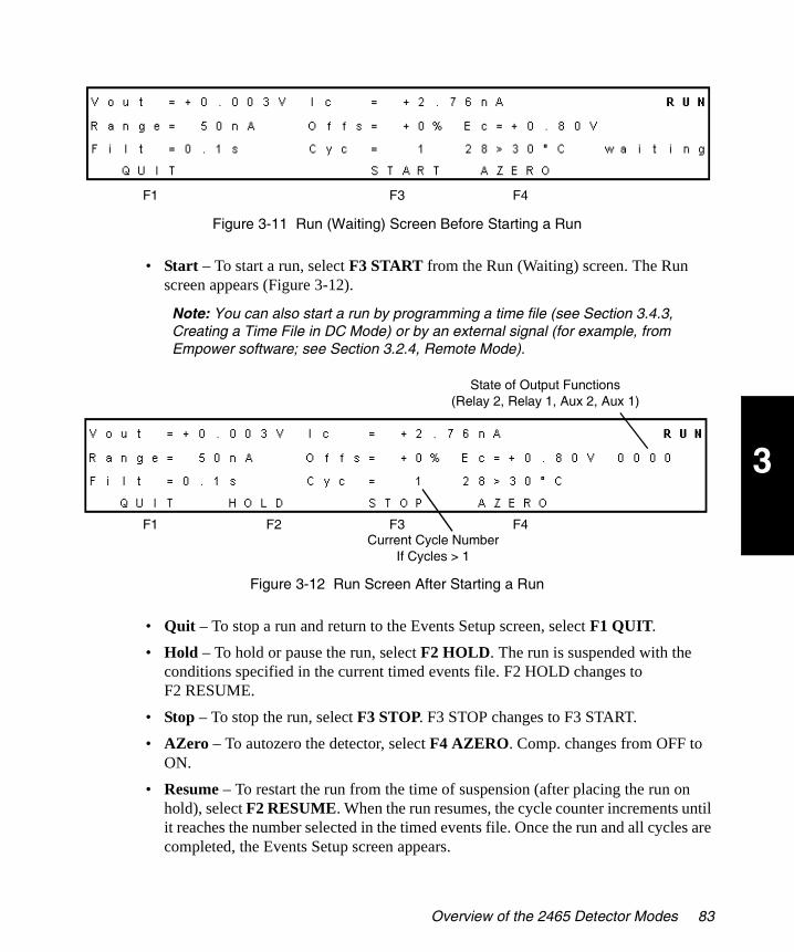
3
2465OG.book Page 83 Wednesday, November 7, 2007 10:33 AM
Figure 3-11 Run (Waiting) Screen Before Starting a Run
• Start – To start a run, select F3 START from the Run (Waiting) screen. The Run screen appears (Figure 3-12).
Note: You can also start a run by programming a time file (see Section 3.4.3, Creating a Time File in DC Mode) or by an external signal (for example, from Empower software; see Section 3.2.4, Remote Mode).
Figure 3-12 Run Screen After Starting a Run
• Quit – To stop a run and return to the Events Setup screen, select F1 QUIT.
• Hold – To hold or pause the run, select F2 HOLD. The run is suspended with the conditions specified in the current timed events file. F2 HOLD changes to F2 RESUME.
• Stop – To stop the run, select F3 STOP. F3 STOP changes to F3 START.
• AZero – To autozero the detector, select F4 AZERO. Comp. changes from OFF to ON.
• Resume – To restart the run from the time of suspension (after placing the run on hold), select F2 RESUME. When the run resumes, the cycle counter increments until it reaches the number selected in the timed events file. Once the run and all cycles are completed, the Events Setup screen appears.
F1 F3 F4
F1 F2 F3 F4Current Cycle Number
If Cycles > 1
State of Output Functions(Relay 2, Relay 1, Aux 2, Aux 1)
Overview of the 2465 Detector Modes 83

3
2465OG.book Page 84 Wednesday, November 7, 2007 10:33 AM
• Run Continuously – To run continuously, select CONT (continuous) for cycles in the Setup screen (Cyc = CONT). The Run screen appears (Figure 3-12) and the detector runs under the current conditions until you select F1 QUIT.
End Cycle Time
Select F5 ENDCYCLE to see the final line for the file and to check whether the time file is empty or not.
• If the number under PROG is 01 or if the end cycle time is 000.01 (Figure 3-13), the time file is empty and ready to edit. Select F1 PREV.
Figure 3-13 End Cycle Time Screen for an Empty Time File
• If the number under PROG (in the upper-right corner) is greater than 1 or if the end cycle time is greater than 000.01, the time file is already programmed.
• If the file contains timed events that you want to save for later use, select another file in the Events Setup screen by moving the cursor to File = and pressing the plus or minus value arrow.
• If the file contains timed events that are no longer used, you can erase one or more lines or the entire time file as follows:
– To delete one line – Select F4 SCROLL until the line that you want to delete appears, then select F3 DEL. At the question Delete time nnn.nn ?, select F2 YES. Repeat if you want to delete more lines in the time file.
– To delete the entire file – Select F4 SCROLL repeatedly until Time = 000.00 min, then select F3 DEL. At the question Delete timefile ?, select F2 YES.
3.2.6 Programming Output Event Functions in Time Files
Four output event functions can be programmed at each time. The notation of the output 0000 corresponds to the four output controls at the back panel of the controller. These are relay 1, relay 2, AUX1, and AUX2 (see Section 2.5, Making I/O Signal Connections).
F1
Represents 112.34 min
84 Operating the 2465 Detector
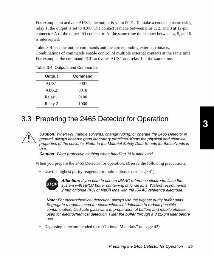
3
2465OG.book Page 85 Wednesday, November 7, 2007 10:33 AM
For example, to activate AUX1, the output is set to 0001. To make a contact closure using relay 1, the output is set to 0100. The contact is made between pins 1, 2, and 3 at 12-pin connector A of the upper I/O connector. At the same time the contact between 4, 5, and 6 is interrupted.
Table 3-4 lists the output commands and the corresponding external contacts. Combinations of commands enable control of multiple external contacts at the same time. For example, the command 0101 activates AUX1 and relay 1 at the same time.
3.3 Preparing the 2465 Detector for Operation
When you prepare the 2465 Detector for operation, observe the following precautions:
• Use the highest purity reagents for mobile phases (see page 41).
Note: For electrochemical detection, always use the highest purity buffer salts. Segregate reagents used for electrochemical detection to reduce possible contamination. Dedicate glassware to preparation of buffers and mobile phases used for electrochemical detection. Filter the buffer through a 0.22-µm filter before use.
• Degassing is recommended (see “Optional Materials” on page 42).
Table 3-4 Outputs and Commands
Output Command
AUX1 0001
AUX2 0010
Relay 1 0100
Relay 2 1000
Caution: When you handle solvents, change tubing, or operate the 2465 Detector in general, always observe good laboratory practices. Know the physical and chemical properties of the solvents. Refer to the Material Safety Data Sheets for the solvents in use.Caution: Wear protective clothing when handling 15% nitric acid.
Attention: If you plan to use an ISAAC reference electrode, flush the system with HPLC buffer containing chloride ions. Waters recommends 2 mM chloride (KCl or NaCl) ions with the ISAAC reference electrode.
Preparing the 2465 Detector for Operation 85

3
2465OG.book Page 86 Wednesday, November 7, 2007 10:33 AM
Note: Air bubbles passing through the flow cell can create unacceptable noise levels and spikes.
• A pulse dampener is recommended (see “Optional Materials” on page 42).
• Column pretreatment is required because a new column is not electrochemically clean and will most likely bleed, causing problems (see Section 2.4.2, Connecting a Column).
• Do not overtighten the fingertight fittings (see Section 2.4.3, Installing the Flow Cell).
• Passivation with nitric acid is required for the metal parts of the HPLC system (see Section 2.4.1, Installing the 2465 Detector).
• Follow special precautions for mobile phase preparation for pulse mode (see “Materials Required But Not Supplied” on page 41 and “Optional Materials” on page 42).
Attention: To prevent unacceptably high background current and substantial fouling of the working electrode, use a column that is electrochemically clean. A new column is not electrochemically clean.
Attention: Use only factory-supplied fingertight fittings in the flow cell, because others may cause serious damage. Let the tubing protrude approximately 0.6 inch (1.5 cm) from the fitting and tighten it such that the tubing is not or slightly indented by the fitting. Do not overtighten the fitting because overtightening affects the flow pattern through the tubing (turbulence) and may strongly decrease the flow cell performance.
Caution: When you handle solvents, change tubing, or operate the 2465 Detector in general, always observe good laboratory practices. Know the physical and chemical properties of the solvents. Refer to the Material Safety Data Sheets for the solvents in use.Caution: Wear protective clothing when handling 15% nitric acid.
Attention: Passivation should include only the metal parts of the HPLC system. Disconnect all parts that are not acid-resistant (such as nylon inlet filters, degasser, pulse dampener, column, and flow cell) during passivation. Do not expose columns or flow cells to 15% nitric acid.
Ensure that all parts that are not acid-resistant (such as the nylon inlet filters, column, and flow cell) are disconnected during passivation. Do not passivate the 2465 Detector.
86 Operating the 2465 Detector

3
2465OG.book Page 87 Wednesday, November 7, 2007 10:33 AM
• Special precautions for reductive mode measurement (see Section 2.4.2, Connecting a Column, on page 47).
3.3.1 Preparing the Detector for Remote Control from Empower
To prepare the 2465 Detector for operation under remote control, first set up the detector, then install the Empower Instrument Control Options Pack on the Empower PC.
Setting Up the Detector
To set up the detector:
1. Connect the 2465 Detector to any available COM port on the Empower PC using a standard RS-232 cable. The COM port configuration is set up automatically by the 2465 Empower Instrument Interface software (see Section 2.6, Verifying COM Port Settings).
2. Log in to Empower Pro or QuickStart.
3. If you have the privileges to do so, click Configure System to access Configuration Manager.
Note: The acquisition server PC serial ports must be configured before you can configure the 2465 Detector in a system.
Note: You must have the security privileges that allow you to access Configure System (Configuration Manager) functions in Empower software.
4. Configure the PC serial ports for the 2465 Detector:
a. Click Acquisition Servers, then right-click the acquisition server and select Properties. The Acquisition Server dialog box appears.
b. Click the Serial Ports tab (Figure 3-14).
c. Select W2465 for COM1 or COM2 under PC Serial Ports.
d. Click the Instruments tab. The software configures the serial ports, then scans the busLAC/E.
e. Verify that the 2465 Detector appears at the address you specified, then click OK. The acquisition server configuration is updated.
Note: If a serial card is used, then configure the 8-port serial card instead of the PC ports.
Attention: If you plan to use an ISAAC reference electrode, flush the system with HPLC buffer containing 2 mM chloride (KCl or NaCl) ions.
Preparing the 2465 Detector for Operation 87

3
2465OG.book Page 88 Wednesday, November 7, 2007 10:33 AM
Figure 3-14 Acquisition Server Dialog Box
Installing the Empower Instrument Control Options Pack
The Empower Instrument Control Options Pack is installed on a Personal, Workgroup, or Client PC that already has Empower software. You must have the security privileges that allow you to access Configure System (Configuration Manager) functions in Empower software.
Note: As a prerequisite, Empower software must be installed on the Personal, Workgroup, or Client PC before installing the Empower Instrument Control Options Pack.
To install the Empower Instrument Control Options Pack on the Empower Personal, Workgroup, or Client PC:
1. Log out and close Empower software, then reboot the acquisition PC to which the 2465 Detector will be connected.
2. Insert the Empower Instrument Control Options Pack CD into the CD-ROM drive. The installation starts automatically and the Welcome page appears.
3. Follow the instructions in the InstallShield Wizard to install the Waters 2465 Software.
4. When the installation is finished, remove the CD from the Empower PC and store it in a protected location.
88 Operating the 2465 Detector

3
2465OG.book Page 89 Wednesday, November 7, 2007 10:33 AM
5. In Empower software, configure an acquisition system that includes the 2465 Detector. For details, see the Empower Help.
Note: For more information about RS-232 communications, see Section 2.5.5, Making RS-232 Connections.
6. In Empower software, configure a new instrument method that includes the 2465 Detector. For details, see the Empower Help. For information about using the 2465 Detector with Empower software, see Section 3.2.4, Remote Mode.
3.3.2 Changing from Remote Mode to Stand-Alone Mode
If you want to use the 2465 Detector in stand-alone mode after control by Empower software (remote mode), Waters strongly recommends that you restart the 2465 Detector (turn the 2465 Detector off, wait 10 seconds, then turn it on).
Note: The parameter settings may differ between remote mode and stand-alone mode.
3.3.3 Equilibrating the Detector
Use this procedure to equilibrate the detector in stand-alone mode, which helps to ensure a stable temperature and operating environment. You can also program an event in a time file to equilibrate the detector (see Section 3.4.3, Creating a Time File in DC Mode).
Note: If operating in remote mode, use Empower software to equilibrate the detector.
To equilibrate the 2465 Detector:
1. From the Main screen, select F2 DC. The DC Setup screen appears (Figure 3-15).
Figure 3-15 DC Setup Screen
Note: You can also select F3 PULSE, then set the temperature in the Pulse Setup1 screen, or select F4 SCAN, then set the temperature in the Scan Setup screen.
2. To set the temperature of the detector oven:
a. Using the cursor keys, move the cursor to Temp. The current setting is displayed (not the actual temperature of the detector oven).
F1 F3 F4 F5
Preparing the 2465 Detector for Operation 89
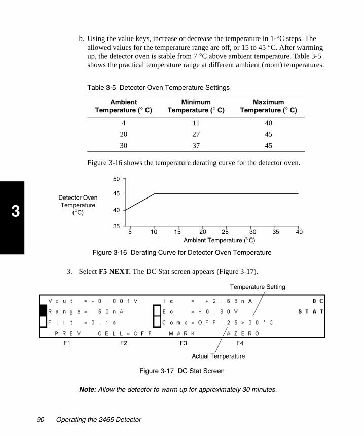
3
2465OG.book Page 90 Wednesday, November 7, 2007 10:33 AM
b. Using the value keys, increase or decrease the temperature in 1-°C steps. The allowed values for the temperature range are off, or 15 to 45 °C. After warming up, the detector oven is stable from 7 °C above ambient temperature. Table 3-5 shows the practical temperature range at different ambient (room) temperatures.
Figure 3-16 shows the temperature derating curve for the detector oven.
Figure 3-16 Derating Curve for Detector Oven Temperature
3. Select F5 NEXT. The DC Stat screen appears (Figure 3-17).
Figure 3-17 DC Stat Screen
Note: Allow the detector to warm up for approximately 30 minutes.
Table 3-5 Detector Oven Temperature Settings
Ambient Temperature (° C)
Minimum Temperature (° C)
Maximum Temperature (° C)
4 11 40
20 27 45
30 37 45
5
Detector OvenTemperature
(°C)
Ambient Temperature (°C)10 15 20 25 30 35 40
35
40
45
50
Actual Temperature
Temperature Setting
F1 F2 F3 F4
90 Operating the 2465 Detector

3
2465OG.book Page 91 Wednesday, November 7, 2007 10:33 AM
4. While the detector is warming up, turn on the pump and allow the mobile phase to flow at 0.5 to 1.0 mL/min.
5. Monitor the temperature and the baseline until they are stable.
6. Switch on the flow cell (see Section 3.4.2, Section 3.5.5, or Section 3.6.2).
7. With mobile phase flowing, allow the detector to equilibrate at least 60 minutes before beginning to acquire data.
Your system is now ready for use. The 2465 Detector has been developed for continuous operation. If preferred, the flow cell can be turned off at night (see Section 3.8.1, Turning Off the Flow Cell).
3.4 Using DC Mode
You can use DC mode to perform direct current (DC) analyses. After you are comfortable with the 2465 Detector, use Table 3-6 for a quick reference list of tasks in DC mode.
Attention: To prevent damage to the flow cell, ensure that the pressure does not increase above 40 psi (2.76 bar, 276 kPa).
Attention: For maximum stability, keep the system powered on continuously.
Table 3-6 DC Mode Quick Reference List
Task in DC Mode Starting Screen Command Sequence
Check settings MAIN F2 DC > F5 NEXT
Make a chart mark DC SETUP F5 NEXT > F3 MARK
Turn the flow cell on or off DC SETUP F5 NEXT > F2 CELL=.... > F2 YES
Change polarity DC SETUP F3 POLAR=... > F2 YES
Autozero the detector DC SETUP F5 NEXT > F4 AZERO
Run without a time file DC SETUP F5 NEXT
Create and run a time file DC SETUP F4 EVENTS > F5 NEXT > [change values as needed] > F2 ADD > [repeat last 2 steps for each line] > F1 PREV > F3 RUN > F3 START
Using DC Mode 91
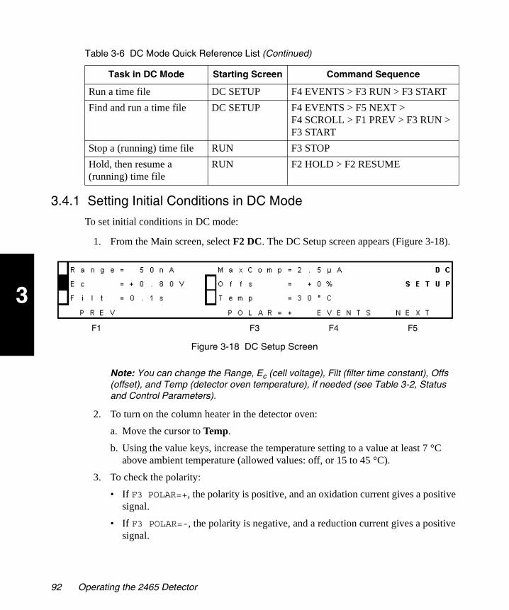
3
2465OG.book Page 92 Wednesday, November 7, 2007 10:33 AM
3.4.1 Setting Initial Conditions in DC Mode
To set initial conditions in DC mode:
1. From the Main screen, select F2 DC. The DC Setup screen appears (Figure 3-18).
Figure 3-18 DC Setup Screen
Note: You can change the Range, Ec (cell voltage), Filt (filter time constant), Offs (offset), and Temp (detector oven temperature), if needed (see Table 3-2, Status and Control Parameters).
2. To turn on the column heater in the detector oven:
a. Move the cursor to Temp.
b. Using the value keys, increase the temperature setting to a value at least 7 °C above ambient temperature (allowed values: off, or 15 to 45 °C).
3. To check the polarity:
• If F3 POLAR=+, the polarity is positive, and an oxidation current gives a positive signal.
• If F3 POLAR=-, the polarity is negative, and a reduction current gives a positive signal.
Run a time file DC SETUP F4 EVENTS > F3 RUN > F3 START
Find and run a time file DC SETUP F4 EVENTS > F5 NEXT > F4 SCROLL > F1 PREV > F3 RUN > F3 START
Stop a (running) time file RUN F3 STOP
Hold, then resume a (running) time file
RUN F2 HOLD > F2 RESUME
Table 3-6 DC Mode Quick Reference List (Continued)
Task in DC Mode Starting Screen Command Sequence
F1 F3 F4 F5
92 Operating the 2465 Detector
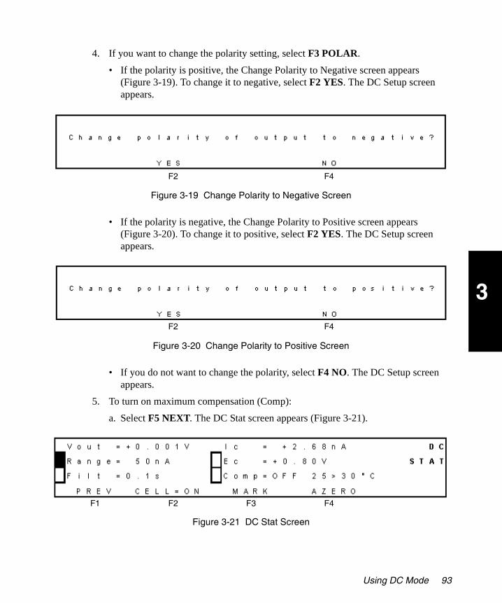
3
2465OG.book Page 93 Wednesday, November 7, 2007 10:33 AM
4. If you want to change the polarity setting, select F3 POLAR.
• If the polarity is positive, the Change Polarity to Negative screen appears (Figure 3-19). To change it to negative, select F2 YES. The DC Setup screen appears.
Figure 3-19 Change Polarity to Negative Screen
• If the polarity is negative, the Change Polarity to Positive screen appears (Figure 3-20). To change it to positive, select F2 YES. The DC Setup screen appears.
Figure 3-20 Change Polarity to Positive Screen
• If you do not want to change the polarity, select F4 NO. The DC Setup screen appears.
5. To turn on maximum compensation (Comp):
a. Select F5 NEXT. The DC Stat screen appears (Figure 3-21).
Figure 3-21 DC Stat Screen
F2 F4
F2 F4
F1 F2 F3 F4
Using DC Mode 93

3
2465OG.book Page 94 Wednesday, November 7, 2007 10:33 AM
b. Using the cursor keys, select Comp.
c. Using either value key, change OFF to ON.
Note: You can also change the Range, Filt (filter time constant), and Ec (cell voltage), if needed (see Table 3-2, Status and Control Parameters).
6. Following all precautions, turn on the flow cell (see Section 3.4.2, Turning the Flow Cell On and Off in DC Mode), and allow the 2465 Detector to equilibrate.
3.4.2 Turning the Flow Cell On and Off in DC Mode
Note: In electrochemical detection, switching the flow cell on or off is like switching a lamp in a UV detector on or off: both events destabilize the system. It takes some time before conditions are stabilized. Stabilization time depends on the range setting, and gets longer at more sensitive range settings.
To turn the flow cell on in DC mode:
1. From the Main screen, select F2 DC. The DC Setup screen appears.
2. Select F5 NEXT. The DC Stat screen appears (Figure 3-22) and the value for F2 CELL is OFF.
Attention: Before powering on the flow cell, ensure that:
The flow cell is filled with 20 to 100 mM electrolyte (buffer) that contains sufficient electrolyte (buffer ions). A flow cell filled with water is not adequate. A stable baseline will never be obtained if the cell is powered on with only water or another nonconducting mobile phase.
No air bubbles are trapped in the flow cell.
The outlet tubing from the flow cell leads to a waste container that is at a higher level than the flow cell. This ensures a minimum amount of backpressure, which prevents air-bubble entrapment. The outlet tubing should be under the liquid level to prevent electrical baseline noise.
Attention: To prevent substantial damage to the working electrode or electronics, never power on the flow cell when:
The cell cable is not correctly connected.
The cell is only partly (or not at all) filled with buffer (not HPLC water).
The outside of the flow cell is wet, particularly the part between the auxiliary and working electrode connection.
94 Operating the 2465 Detector

3
2465OG.book Page 95 Wednesday, November 7, 2007 10:33 AM
Figure 3-22 DC Stat Screen with Cell Off
3. Select F2 CELL=OFF. The Switch Cell On screen appears (Figure 3-23).
Figure 3-23 Switch Cell On Screen
4. Select F2 YES. The DC Stat screen appears and the value for F2 CELL is ON.
To turn the flow cell off in DC mode:
1. From the Main screen, select F2 DC. The DC Setup screen appears (Figure 3-18).
2. Select F5 NEXT. The DC Stat screen appears (Figure 3-22) and the value for F2 CELL is ON.
3. Select F2 CELL=ON. The Switch Cell Off screen appears (Figure 3-24).
Figure 3-24 Switch Cell Off Screen
4. Select F2 YES. The DC Stat screen appears and the value for F2 CELL is OFF.
F1 F2 F3 F4
F2 F4
F2 F4
Using DC Mode 95

3
2465OG.book Page 96 Wednesday, November 7, 2007 10:33 AM
3.4.3 Creating a Time File in DC Mode
The following example describes how to program a simple time file in DC mode. Each row in Table 3-7 represents one line to be programmed, and each parameter change represents one event. The entire table represents one time file.
In this example, an autozero is performed at 0.00 minute (initial conditions), the cell potential (Ec) changes at 4.80 minutes, and two events occur at 4.90 minutes (a 10% offset and another autozero). The end cycle time is 5.00 minutes.
To create timed events in DC mode:
1. From the Main screen, select F2 DC. (Alternatively, from the DC Stat screen, select F1 PREV). The DC Setup Screen appears (Figure 3-25).
Figure 3-25 DC Setup Screen
Table 3-7 Programming a Sample Time File in DC Mode
Time (min)
Line No.
Range FiltAutoZero
Output Polar Ecell Offset
000.00 1 50 nA 1 s set 0000 + 0.80 V 0%
004.80 2 50 nA 1 s not 0000 + 0.65 V 0%
004.90 3 50 nA 1 s set 0000 + 0.65 V 10%
005.00 End cycle time (end of run)
F1 F3 F4 F5
96 Operating the 2465 Detector

3
2465OG.book Page 97 Wednesday, November 7, 2007 10:33 AM
2. Select F4 EVENTS. The Events Setup screen appears (Figure 3-26).
Figure 3-26 Events Setup Screen
3. Ensure that the initial conditions are acceptable for your purpose. At a minimum, select the following initial conditions:
a. Time file 1 (File = 1) is the default time file. To program time file 2, select File, then use the value keys to select File = 2.
b. Ensure that the value for the Temp is the same as on the DC Setup screen.
Note: If you want to program a temperature change, allow sufficient time after the change for equilibration.
c. If needed, change the number of cycles to Cycles = 1 using the down cursor key and the value key.
Note: Select a cycle value of 1 when an inject start event in is connected to pins 13 and 15 of the 2465 Detector (see Section 2.5, Making I/O Signal Connections).
d. Select F5 NEXT. The Prog screen appears (Figure 3-27). The number under PROG shows that this time file currently has one line. Time = 000.00 establishes the initial conditions.
Figure 3-27 Prog Screen with Initial Conditions
F1 F3 F5
Time File 1
F1 F2 F3 F4 F5
Minutes Hundredths of a Minute Total Number of Lines in the File
Using DC Mode 97
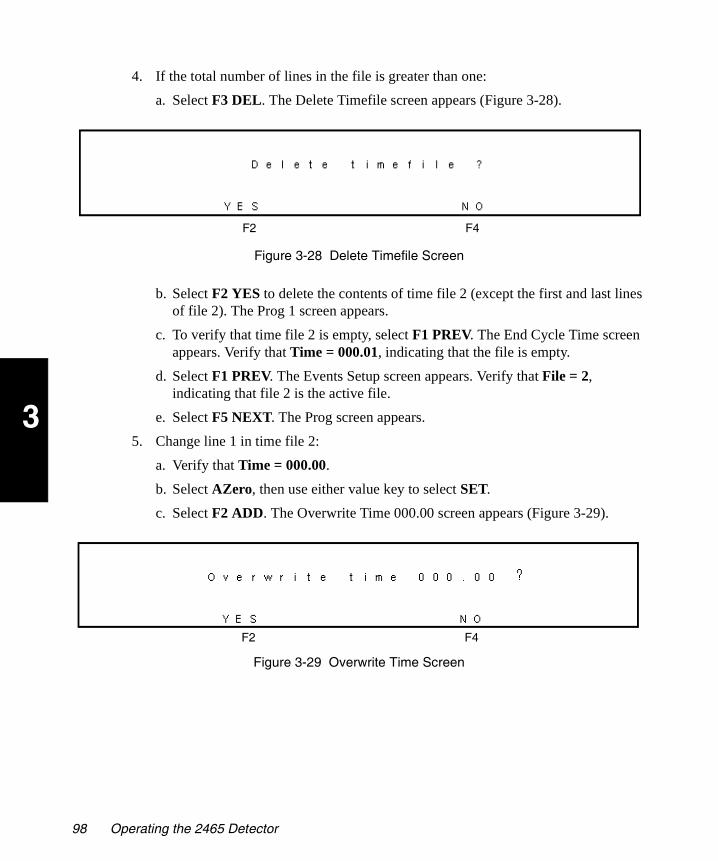
3
2465OG.book Page 98 Wednesday, November 7, 2007 10:33 AM
4. If the total number of lines in the file is greater than one:
a. Select F3 DEL. The Delete Timefile screen appears (Figure 3-28).
Figure 3-28 Delete Timefile Screen
b. Select F2 YES to delete the contents of time file 2 (except the first and last lines of file 2). The Prog 1 screen appears.
c. To verify that time file 2 is empty, select F1 PREV. The End Cycle Time screen appears. Verify that Time = 000.01, indicating that the file is empty.
d. Select F1 PREV. The Events Setup screen appears. Verify that File = 2, indicating that file 2 is the active file.
e. Select F5 NEXT. The Prog screen appears.
5. Change line 1 in time file 2:
a. Verify that Time = 000.00.
b. Select AZero, then use either value key to select SET.
c. Select F2 ADD. The Overwrite Time 000.00 screen appears (Figure 3-29).
Figure 3-29 Overwrite Time Screen
F2 F4
F2 F4
98 Operating the 2465 Detector

3
2465OG.book Page 99 Wednesday, November 7, 2007 10:33 AM
d. Select F2 YES. The Prog screen appears (Figure 3-30).
Figure 3-30 Prog Screen After Changing Line 1
6. Create line 2:
a. Select Time.
b. Move the cursor to minutes, then change the value to 4.
c. Move the cursor to hundredths of a minute, then change the value to 80.
d. Select Ec, then change the value to +0.65V. The suffix # appears when the cell potential changes (Figure 3-31).
Figure 3-31 Prog Screen After Changing Cell Potential
e. Press the Enter key to confirm the change to Ec. The suffix # disappears.
f. Select AZero, then change the value to NOT.
g. Select F2 ADD. The Prog screen appears (Figure 3-32).
Figure 3-32 Prog Screen After Adding Line 2
F2 F4F1 F3 F5
F1 F2 F3 F4 F5
F1 F2 F3 F4 F5
Using DC Mode 99
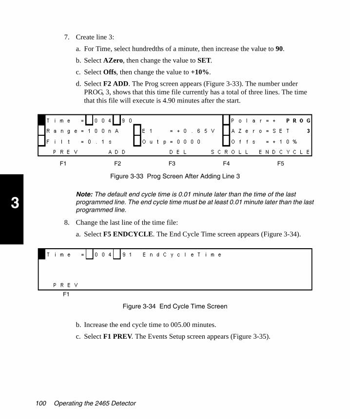
3
2465OG.book Page 100 Wednesday, November 7, 2007 10:33 AM
7. Create line 3:
a. For Time, select hundredths of a minute, then increase the value to 90.
b. Select AZero, then change the value to SET.
c. Select Offs, then change the value to +10%.
d. Select F2 ADD. The Prog screen appears (Figure 3-33). The number under PROG, 3, shows that this time file currently has a total of three lines. The time that this file will execute is 4.90 minutes after the start.
Figure 3-33 Prog Screen After Adding Line 3
Note: The default end cycle time is 0.01 minute later than the time of the last programmed line. The end cycle time must be at least 0.01 minute later than the last programmed line.
8. Change the last line of the time file:
a. Select F5 ENDCYCLE. The End Cycle Time screen appears (Figure 3-34).
Figure 3-34 End Cycle Time Screen
b. Increase the end cycle time to 005.00 minutes.
c. Select F1 PREV. The Events Setup screen appears (Figure 3-35).
F1 F2 F3 F4 F5
F1
100 Operating the 2465 Detector

3
2465OG.book Page 101 Wednesday, November 7, 2007 10:33 AM
Figure 3-35 Events Setup Screen with Time File 2
9. Review all four lines in time file 2:
a. Select F5 NEXT. The Prog 3 screen appears, and Time = 000.00 minutes.
b. Review the values for the first line of time file 2.
c. Select F4 SCROLL. The second line of time file 2 appears, and Time = 004.80 minutes. Review the values.
Note: Lines scroll according to their time (in this case, you should see the lines at times 0.00, 4.80, 4.90, then 5.00, in increasing order, then 0.00 again).
d. Repeat step c for all lines in the time file. Finish at the end cycle time.
e. Select F1 PREV. (If you were not at the end cycle time, the End Cycle Time screen appears. Select F1 PREV.) The Events Setup screen appears.
Time file 2 is ready to run (see Section 3.4.4, Running a Time File in DC Mode).
3.4.4 Running a Time File in DC Mode
To run a time file in DC mode:
1. From the Events Setup screen, select F3 RUN. The Run (Waiting) screen appears (Figure 3-36).
The system waits for a start command. This can be a keypad command or an external trigger from connector A on the rear panel (see Section 2.5, Making I/O Signal Connections).
F1 F3 F5
Using DC Mode 101

3
2465OG.book Page 102 Wednesday, November 7, 2007 10:33 AM
Figure 3-36 Run (Waiting) Screen
2. Select F3 START to start the run. The Run screen appears (Figure 3-37).
Figure 3-37 Run Screen After Starting a Run
3. You can do the following:
• To pause or put the run on hold during the run, select F2 HOLD. When you are ready to resume the run, select F2 RESUME.
• To stop the run, select F3 STOP. The Run (Waiting) screen appears.
• If Cycles is set to Continuous, select F3 STOP, then select F1 QUIT. The run stops and the Events Setup screen appears.
• If Cycles is set to a number from 1 to 999, the Events Setup screen appears at the end of the run.
• When you want to return to the Main screen, select F1 QUIT > F1 PREV > F1 PREV.
F1 F3 F4
F1 F2 F3 F4
102 Operating the 2465 Detector

3
2465OG.book Page 103 Wednesday, November 7, 2007 10:33 AM
3.5 Using Pulse (PAD) Mode
You can use pulse mode to perform pulsed amperometric detection (PAD). After you are comfortable with the 2465 Detector, use Table 3-8 as a quick reference list of tasks in pulse mode.
Table 3-8 Pulse Mode Quick Reference List
Task in Pulse Mode Starting Screen Command Sequence
Check settings MAIN F3 PULSE > F5 NEXT > F5 NEXT
Make a chart mark PULSE SETUP1 F5 NEXT > F5 NEXT > F3 MARK
Turn the flow cell on or off PULSE SETUP1 F5 NEXT > F5 NEXT > F2 CELL=.... > F2 YES
Change polarity PULSE SETUP1 F5 NEXT > F3 POLAR=... > F2 YES
Autozero the detector PULSE SETUP1 F5 NEXT > F5 NEXT > F4 AZERO
Change the range PULSE SETUP1 F5 NEXT > F5 NEXT
Create and run a time file PULSE SETUP1 F5 NEXT > F4 EVENTS > F5 NEXT > [change values as needed] > F2 ADD > [repeat last 2 steps for each line] > F1 PREV > F3 RUN > F3 START
Run a time file PULSE SETUP1 F5 NEXT > F4 EVENTS > F3 RUN > F3 START
Find and run a time file PULSE SETUP1 F5 NEXT > F4 EVENTS > F5 NEXT > [press up or down value keys to select a time file] > F3 RUN > F3 START
Stop a (running) time file RUN F3 STOP
Hold, then resume a (running) time file
RUN F2 HOLD > F2 RESUME
Using Pulse (PAD) Mode 103
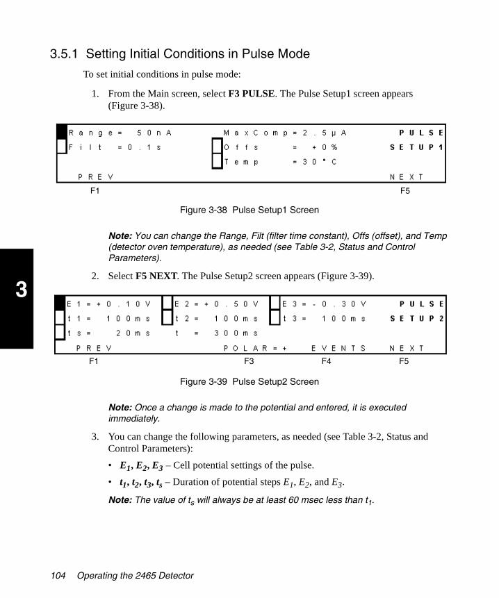
3
2465OG.book Page 104 Wednesday, November 7, 2007 10:33 AM
3.5.1 Setting Initial Conditions in Pulse Mode
To set initial conditions in pulse mode:
1. From the Main screen, select F3 PULSE. The Pulse Setup1 screen appears (Figure 3-38).
Figure 3-38 Pulse Setup1 Screen
Note: You can change the Range, Filt (filter time constant), Offs (offset), and Temp (detector oven temperature), as needed (see Table 3-2, Status and Control Parameters).
2. Select F5 NEXT. The Pulse Setup2 screen appears (Figure 3-39).
Figure 3-39 Pulse Setup2 Screen
Note: Once a change is made to the potential and entered, it is executed immediately.
3. You can change the following parameters, as needed (see Table 3-2, Status and Control Parameters):
• E1, E2, E3 – Cell potential settings of the pulse.
• t1, t2, t3, ts – Duration of potential steps E1, E2, and E3.
Note: The value of ts will always be at least 60 msec less than t1.
F1 F5
F1 F3 F4 F5
104 Operating the 2465 Detector

3
2465OG.book Page 105 Wednesday, November 7, 2007 10:33 AM
4. You can check and change polarity in pulse mode as follows:
• If F3 indicates POLAR=+, the polarity is positive, and an oxidation current gives a positive signal. If F3 indicates POLAR=-, the polarity is negative, and a reduction current gives a positive signal.
• To change the polarity setting, select F3 POLAR.
• If the polarity is positive, the Change Polarity to Negative screen appears (Figure 3-40). To change it to negative, select F2 YES. The Pulse Setup2 screen appears.
Figure 3-40 Change Polarity to Negative Screen
• If the polarity is negative, the Change Polarity to Positive screen appears. To change it to positive, select F2 YES. The Pulse Setup2 screen appears.
• If you do not want to change the polarity, select F4 NO. The Pulse Setup2 screen appears.
5. Select F5 NEXT. The Pulse Stat screen appears (Figure 3-41).
Figure 3-41 Pulse Stat Screen when Flow Cell Is On
If the flow cell is off (see F2 in Figure 3-42), see Section 3.5.5, Turning the Flow Cell On and Off in Pulse Mode.
F2 F4
F1 F2 F3 F4
Using Pulse (PAD) Mode 105

3
2465OG.book Page 106 Wednesday, November 7, 2007 10:33 AM
Figure 3-42 Pulse Stat Screen when Flow Cell Is Off
Note: You can change the Range, E1 (cell voltage), Filt (filter time constant), and Comp (maximum compensation), as needed (see Table 3-2, Status and Control Parameters).
6. You can check the status of the following parameters (see Table 3-2, Status and Control Parameters):
• Verify that the flow cell is on or off (F2).
• Check the actual cell current (output signal in volts) at Vout.
• Check the cell potential (Ic).
• Check the actual detector oven temperature (to the left of the >) and the temperature setting (to the right of the >).
• Track the time since entering the Pulse Stat screen.
7. You can also do the following:
• Select F3 MARK to make a chart mark.
• Select F4 AZERO to autozero the detector.
8. When you want to return to the Main screen, select F1 PREV > F1 PREV > F1 PREV.
3.5.2 Changing the Range in Pulse Mode
To change the range in pulse mode:
1. From the Main screen, select F3 PULSE. The Pulse Setup1 screen appears (Figure 3-38).
2. If Range is not selected, move the cursor to select it.
3. Use the value keys to change the range.
4. Select F5 NEXT. The Pulse Setup2 screen appears (Figure 3-39).
5. Select F5 NEXT. The Pulse Stat screen appears (Figure 3-41).
F1 F2 F3 F4
106 Operating the 2465 Detector
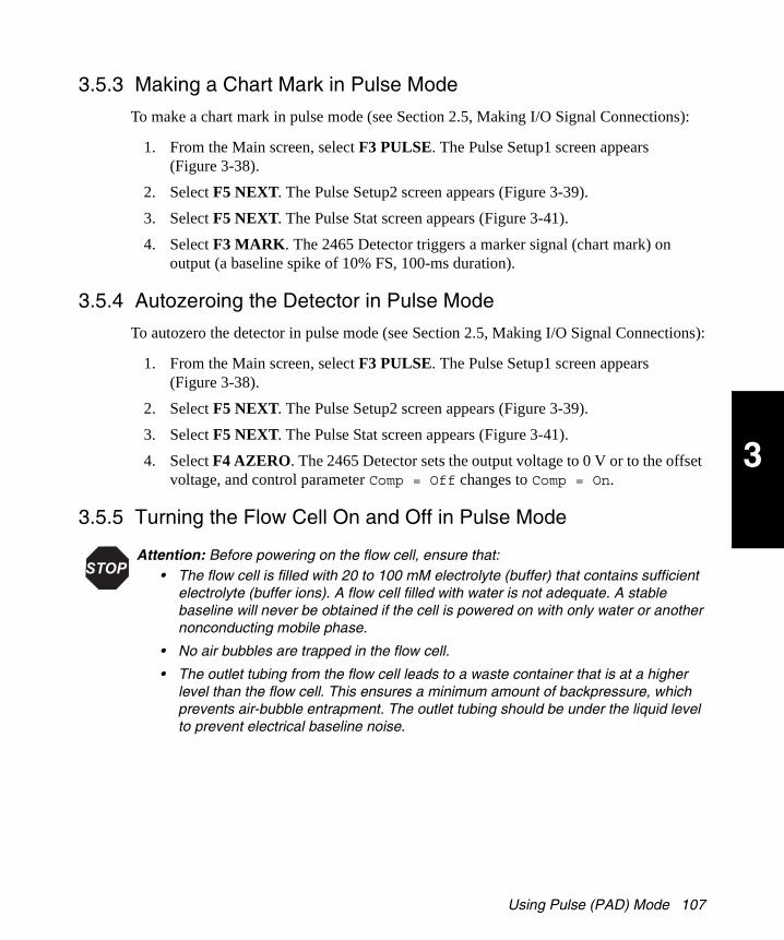
3
2465OG.book Page 107 Wednesday, November 7, 2007 10:33 AM
3.5.3 Making a Chart Mark in Pulse Mode
To make a chart mark in pulse mode (see Section 2.5, Making I/O Signal Connections):
1. From the Main screen, select F3 PULSE. The Pulse Setup1 screen appears (Figure 3-38).
2. Select F5 NEXT. The Pulse Setup2 screen appears (Figure 3-39).
3. Select F5 NEXT. The Pulse Stat screen appears (Figure 3-41).
4. Select F3 MARK. The 2465 Detector triggers a marker signal (chart mark) on output (a baseline spike of 10% FS, 100-ms duration).
3.5.4 Autozeroing the Detector in Pulse Mode
To autozero the detector in pulse mode (see Section 2.5, Making I/O Signal Connections):
1. From the Main screen, select F3 PULSE. The Pulse Setup1 screen appears (Figure 3-38).
2. Select F5 NEXT. The Pulse Setup2 screen appears (Figure 3-39).
3. Select F5 NEXT. The Pulse Stat screen appears (Figure 3-41).
4. Select F4 AZERO. The 2465 Detector sets the output voltage to 0 V or to the offset voltage, and control parameter Comp = Off changes to Comp = On.
3.5.5 Turning the Flow Cell On and Off in Pulse Mode
Attention: Before powering on the flow cell, ensure that:
The flow cell is filled with 20 to 100 mM electrolyte (buffer) that contains sufficient electrolyte (buffer ions). A flow cell filled with water is not adequate. A stable baseline will never be obtained if the cell is powered on with only water or another nonconducting mobile phase.
No air bubbles are trapped in the flow cell.
The outlet tubing from the flow cell leads to a waste container that is at a higher level than the flow cell. This ensures a minimum amount of backpressure, which prevents air-bubble entrapment. The outlet tubing should be under the liquid level to prevent electrical baseline noise.
Using Pulse (PAD) Mode 107

3
2465OG.book Page 108 Wednesday, November 7, 2007 10:33 AM
Note: In electrochemical detection, switching the flow cell on or off is like switching a lamp in a UV detector on or off: both events destabilize the system. It takes some time before conditions are stabilized. Stabilization time depends on the range setting, and gets longer at more sensitive range settings.
To turn the flow cell on in pulse mode:
1. From the Main screen, select F3 PULSE. The Pulse Setup1 screen appears.
2. Select F5 NEXT. The Pulse Setup2 screen appears.
3. Select F5 NEXT. The Pulse Stat screen appears (Figure 3-43) and the value for F2 CELL is OFF.
Figure 3-43 Pulse Stat Screen with Cell Off
4. Select F2 CELL=OFF. The Switch Cell On screen appears (Figure 3-44).
Figure 3-44 Switch Cell On Screen
5. Select F2 YES. The Pulse Stat screen appears and the value for F2 CELL is ON.
Attention: To prevent substantial damage to the working electrode or electronics, never power on the flow cell when:
The cell cable is not correctly connected.
The cell is only partly (or not at all) filled with buffer (not HPLC water).
The outside of the flow cell is wet, particularly the part between the auxiliary and working electrode connection.
F1 F2 F3 F4
F2 F4
108 Operating the 2465 Detector
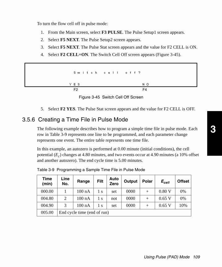
3
2465OG.book Page 109 Wednesday, November 7, 2007 10:33 AM
To turn the flow cell off in pulse mode:
1. From the Main screen, select F3 PULSE. The Pulse Setup1 screen appears.
2. Select F5 NEXT. The Pulse Setup2 screen appears.
3. Select F5 NEXT. The Pulse Stat screen appears and the value for F2 CELL is ON.
4. Select F2 CELL=ON. The Switch Cell Off screen appears (Figure 3-45).
Figure 3-45 Switch Cell Off Screen
5. Select F2 YES. The Pulse Stat screen appears and the value for F2 CELL is OFF.
3.5.6 Creating a Time File in Pulse Mode
The following example describes how to program a simple time file in pulse mode. Each row in Table 3-9 represents one line to be programmed, and each parameter change represents one event. The entire table represents one time file.
In this example, an autozero is performed at 0.00 minute (initial conditions), the cell potential (Ec) changes at 4.80 minutes, and two events occur at 4.90 minutes (a 10% offset and another autozero). The end cycle time is 5.00 minutes.
Table 3-9 Programming a Sample Time File in Pulse Mode
Time (min)
Line No.
Range FiltAutoZero
Output Polar Ecell Offset
000.00 1 100 nA 1 s set 0000 + 0.80 V 0%
004.80 2 100 nA 1 s not 0000 + 0.65 V 0%
004.90 3 100 nA 1 s set 0000 + 0.65 V 10%
005.00 End cycle time (end of run)
F2 F4
Using Pulse (PAD) Mode 109
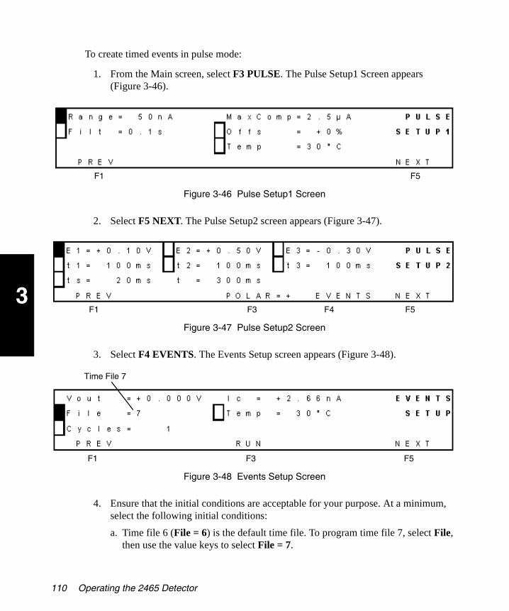
3
2465OG.book Page 110 Wednesday, November 7, 2007 10:33 AM
To create timed events in pulse mode:
1. From the Main screen, select F3 PULSE. The Pulse Setup1 Screen appears (Figure 3-46).
Figure 3-46 Pulse Setup1 Screen
2. Select F5 NEXT. The Pulse Setup2 screen appears (Figure 3-47).
Figure 3-47 Pulse Setup2 Screen
3. Select F4 EVENTS. The Events Setup screen appears (Figure 3-48).
Figure 3-48 Events Setup Screen
4. Ensure that the initial conditions are acceptable for your purpose. At a minimum, select the following initial conditions:
a. Time file 6 (File = 6) is the default time file. To program time file 7, select File, then use the value keys to select File = 7.
F1 F5
F1 F3 F5F4
F1 F3 F5
Time File 7
110 Operating the 2465 Detector

3
2465OG.book Page 111 Wednesday, November 7, 2007 10:33 AM
b. Ensure that the value for the Temp is the same as on the Pulse Setup1 screen.
Note: If you want to program a temperature change, allow sufficient time after the change for equilibration.
c. If needed, change the number of cycles to Cycles = 1 using the down cursor key and the value key.
Note: Select a cycle value of 1 when an inject start event in is connected to pins 13 and 15 of the 2465 Detector (see Section 2.5, Making I/O Signal Connections).
d. Select F5 NEXT. The Prog screen appears (Figure 3-49). The number under PROG shows that this time file currently has one line. Time = 000.00 indicates the initial conditions.
Figure 3-49 Prog Screen with Initial Conditions
5. If the total number of lines in the file is greater than one:
a. Select F3 DEL. The Delete Timefile screen appears (Figure 3-50).
Figure 3-50 Delete Timefile Screen
b. Select F2 YES to delete the contents of time file 7 (except the first and last lines of file 7). The Prog screen appears.
c. To verify that time file 7 is empty, select F1 PREV. The End Cycle Time screen appears. Verify that Time = 000.01, indicating that the file is empty.
F1 F2 F3 F4 F5
Minutes Hundredths of a Minute Total Number of Lines in the File
F2 F4
Using Pulse (PAD) Mode 111

3
2465OG.book Page 112 Wednesday, November 7, 2007 10:33 AM
d. Select F1 PREV. The Events Setup screen appears. Verify that File = 7, indicating that file 7 is the active file.
e. Select F5 NEXT. The Prog screen appears.
6. Change line 1 in time file 7:
a. Verify that Time = 000.00.
b. Select AZero, then use either value key to select SET.
c. Select F2 ADD. The Overwrite Time screen appears (Figure 3-51).
Figure 3-51 Overwrite Time Screen
d. Select F2 YES. The Prog screen appears (Figure 3-52).
Figure 3-52 Prog Screen After Changing Line 1
7. Create line 2:
a. Select Time.
b. Move the cursor to minutes, then change the value to 4.
c. Move the cursor to hundredths of a minute, then change the value to 80.
d. Move the cursor to Range, then change the value to 100.
e. Select E1, then change the value to +0.65V. The suffix # appears when the cell potential changes.
f. Press the Enter key to confirm the change to E1. The suffix # disappears.
g. Select AZero, then change the value to NOT.
F2 F4
F2 F4F1 F3 F5
112 Operating the 2465 Detector

3
2465OG.book Page 113 Wednesday, November 7, 2007 10:33 AM
h. Select F2 ADD. The Prog screen appears (Figure 3-53).
Figure 3-53 Prog Screen After Adding Line 2
8. Create line 3:
a. For Time, select hundredths of a minute, then increase the value to 90.
b. Select AZero, then change the value to SET.
c. Select Offs, then change the value to +10%.
d. Select F2 ADD. The Prog screen appears (Figure 3-54). The number under PROG, 3, shows that this time file currently has a total of three lines. The time that this file will execute is 4.90 minutes after the start.
Figure 3-54 Prog Screen After Adding Line 3
Note: The default end cycle time is 0.01 minute later than the time of the last programmed line. The end cycle time must be at least 0.01 minute later than the last programmed line.
9. Change the last line of the time file:
a. Select F5 ENDCYCLE. The End Cycle Time screen appears (Figure 3-55).
F1 F2 F3 F4 F5
F1 F2 F3 F4 F5
Using Pulse (PAD) Mode 113
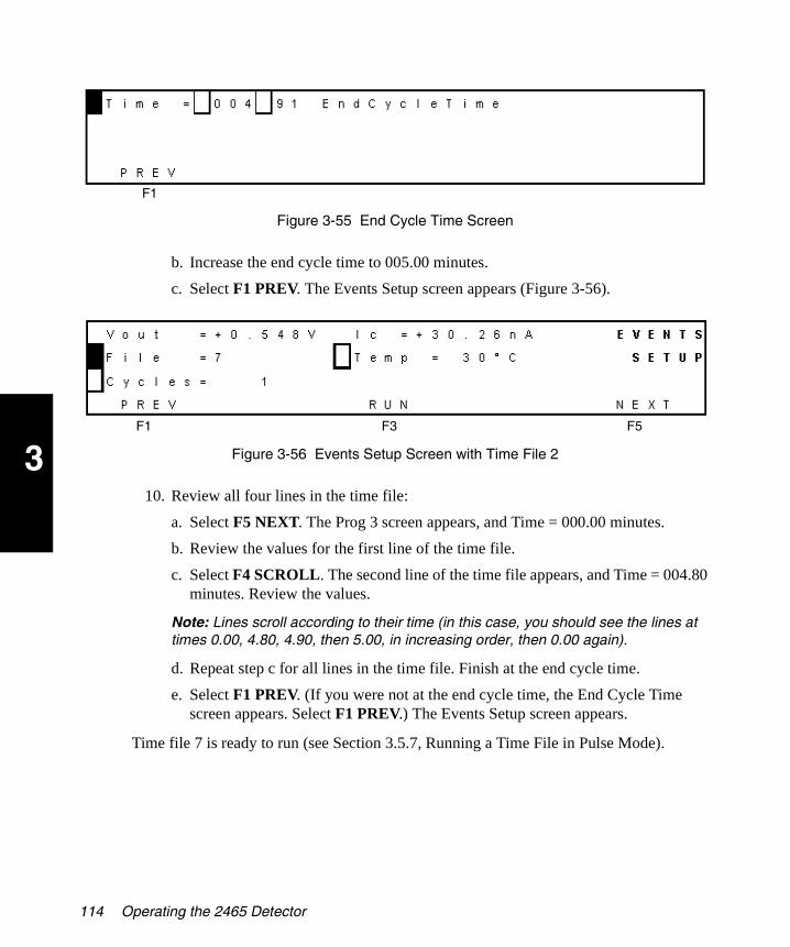
3
2465OG.book Page 114 Wednesday, November 7, 2007 10:33 AM
Figure 3-55 End Cycle Time Screen
b. Increase the end cycle time to 005.00 minutes.
c. Select F1 PREV. The Events Setup screen appears (Figure 3-56).
Figure 3-56 Events Setup Screen with Time File 2
10. Review all four lines in the time file:
a. Select F5 NEXT. The Prog 3 screen appears, and Time = 000.00 minutes.
b. Review the values for the first line of the time file.
c. Select F4 SCROLL. The second line of the time file appears, and Time = 004.80 minutes. Review the values.
Note: Lines scroll according to their time (in this case, you should see the lines at times 0.00, 4.80, 4.90, then 5.00, in increasing order, then 0.00 again).
d. Repeat step c for all lines in the time file. Finish at the end cycle time.
e. Select F1 PREV. (If you were not at the end cycle time, the End Cycle Time screen appears. Select F1 PREV.) The Events Setup screen appears.
Time file 7 is ready to run (see Section 3.5.7, Running a Time File in Pulse Mode).
F1
F1 F3 F5
114 Operating the 2465 Detector

3
2465OG.book Page 115 Wednesday, November 7, 2007 10:33 AM
3.5.7 Running a Time File in Pulse Mode
To run a time file in pulse mode:
1. From the Events Setup screen, select F3 RUN. The Run (Waiting) screen appears (Figure 3-57), and the system waits for a start command. This can be a keypad command or an external trigger from connector A on the rear panel (see Section 2.5, Making I/O Signal Connections).
Figure 3-57 Run (Waiting) Screen
2. Select F3 START to start the run. The Run screen appears (Figure 3-58).
Figure 3-58 Run Screen After Starting a Run
3. You can do the following:
• To pause or put the run on hold during the run, select F2 HOLD. When you are ready to resume the run, select F2 RESUME.
• To stop the run, select F3 STOP. The Run (Waiting) screen appears.
• If Cycles is set to Continuous, select F3 STOP, then select F1 QUIT. The run stops and the Events Setup screen appears.
• When you want to return to the Main screen, select F1 QUIT > F1 PREV > F1 PREV > F1 PREV.
Note: If Cycles is set to a number from 1 to 999, the Events Setup screen appears at the end of the run.
F1 F3 F4
F1 F2 F3 F4
Using Pulse (PAD) Mode 115

3
2465OG.book Page 116 Wednesday, November 7, 2007 10:33 AM
3.6 Using Scan Mode
You can use scan mode to perform simple scans. After you are comfortable with the 2465 Detector, use Table 3-10 as a quick reference list of tasks in scan mode.
3.6.1 Setting Initial Conditions in Scan Mode
To set the initial conditions in scan mode:
1. From the Main screen, select F4 SCAN. The Scan Setup screen appears (Figure 3-59).
Figure 3-59 Scan Setup Screen
2. You can change E1 and E2 (cell voltage), Range, Offs (offset), SPD (scan speed), Cyc (cycle length), and Temp (detector oven temperature), as needed (see Table 3-2, Status and Control Parameters).
3. Select F5 NEXT. The Scan Stat screen appears (Figure 3-60, with 10 V full scale).
Table 3-10 Scan Mode Quick Reference List
Task in Scan Mode Starting Screen Command Sequence
Check settings MAIN F4 SCAN
Change the temperature setting and monitor it
MAIN F4 SCAN (to change the setting), then F5 NEXT (to monitor the temperature)
Turn the flow cell on or off SCAN SETUP F3 CELL=.... > F2 YES
Start a scan SCAN SETUP F5 NEXT > F2 START
Stop a scan SCAN STAT F2 STOP
Hold, then resume a scan SCAN STAT F5 HOLD > F5 RESUME
F1 F3 F5
116 Operating the 2465 Detector

3
2465OG.book Page 117 Wednesday, November 7, 2007 10:33 AM
Figure 3-60 Scan Stat Screen
4. You can change the Range and Offs (offset), as needed (see Table 3-2, Status and Control Parameters).
3.6.2 Turning the Flow Cell On and Off in Scan Mode
Note: In electrochemical detection, switching the flow cell on or off is like switching a lamp in a UV detector on or off: both events destabilize the system. It takes some time before conditions are stabilized. Stabilization time depends on the range setting, and gets longer at more sensitive range settings.
To turn the flow cell on in scan mode:
1. From the Main screen, select F4 SCAN. The Scan Setup screen appears (Figure 3-61) and the value for F3 CELL is OFF.
Attention: Before powering on the flow cell, ensure that:
The flow cell is filled with 20 to 100 mM electrolyte (buffer) that contains sufficient electrolyte (buffer ions). A flow cell filled with water is not adequate. A stable baseline will never be obtained if the cell is powered on with only water or another nonconducting mobile phase.
No air bubbles are trapped in the flow cell.
The outlet tubing from the flow cell leads to a waste container that is at a higher level than the flow cell. This ensures a minimum amount of backpressure, which prevents air-bubble entrapment. The outlet tubing should be under the liquid level to prevent electrical baseline noise.
Attention: To prevent substantial damage to the working electrode or electronics, never power on the flow cell when:
The cell cable is not correctly connected.
The cell is only partly (or not at all) filled with buffer (not HPLC water).
The outside of the flow cell is wet, particularly the part between the auxiliary and working electrode connection.
F1 F2 F3
Using Scan Mode 117
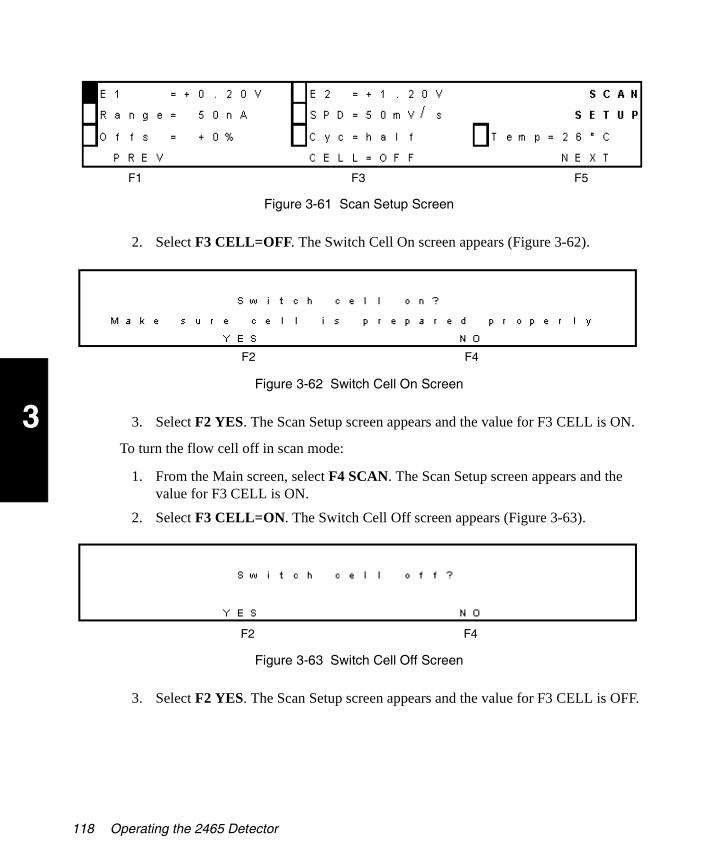
3
2465OG.book Page 118 Wednesday, November 7, 2007 10:33 AM
Figure 3-61 Scan Setup Screen
2. Select F3 CELL=OFF. The Switch Cell On screen appears (Figure 3-62).
Figure 3-62 Switch Cell On Screen
3. Select F2 YES. The Scan Setup screen appears and the value for F3 CELL is ON.
To turn the flow cell off in scan mode:
1. From the Main screen, select F4 SCAN. The Scan Setup screen appears and the value for F3 CELL is ON.
2. Select F3 CELL=ON. The Switch Cell Off screen appears (Figure 3-63).
Figure 3-63 Switch Cell Off Screen
3. Select F2 YES. The Scan Setup screen appears and the value for F3 CELL is OFF.
F1 F3 F5
F2 F4
F2 F4
118 Operating the 2465 Detector

3
2465OG.book Page 119 Wednesday, November 7, 2007 10:33 AM
3.6.3 Performing a Scan in Scan Mode
To perform a scan in scan mode:
1. From the Main screen, select F4 SCAN. The Scan Setup screen appears (Figure 3-64).
Figure 3-64 Scan Setup Screen
2. You can change E1 and E2 (cell voltage), Range, Offs (offset), SPD (scan speed), Cyc (cycle length), and Temp (detector oven temperature), as needed.
3. Select F5 NEXT. The Scan Stat screen appears (Figure 3-65).
Figure 3-65 Scan Stat Screen
4. To prepare for a scan:
a. If you see an Out of Range message on the top row, increase the range, then allow sufficient time for Vout and Ic values to appear.
b. You can change the value for offset (Offs), as needed.
c. Monitor the actual temperature until it stabilizes.
d. Ensure the flow cell is on (see Section 3.6.2, Turning the Flow Cell On and Off in Scan Mode).
5. Select F2 START. The Scan Stat screen appears (Figure 3-66).
F1 F3 F5
Actual Temperature Temperature Setting
F1 F2 F3
Using Scan Mode 119

3
2465OG.book Page 120 Wednesday, November 7, 2007 10:33 AM
Figure 3-66 Starting a Scan
6. If you need to stop the scan, select F2 STOP.
You can also select F5 HOLD to pause or put the scan on hold. The values for Vout and Ic continue to change. Select F5 RESUME to resume the scan.
7. When the scan is finished, select F2 STOP.
8. When you want to return to the Main screen, select F1 PREV > F1 PREV.
3.7 Optimizing the Working Potential
You must optimize the working potential for each different set of conditions or methods in which you plan to run samples (temperature, flow cell size, electrodes, mobile phase, flow rate, sample composition, column, and so on).
3.7.1 Constructing a Hydrodynamic Voltammogram
To construct a hydrodynamic voltammogram:
1. Prepare a solution of the analyte at a concentration between 1 and 100 µM/L in mobile phase.
2. Allow approximately 60 minutes to stabilize the electrochemical detector in DC mode at a high potential, at the selected temperature, with the flow cell off.
3. Read the background current from the display of the detector (Ic) and measure the noise.
Attention: Before attempting to obtain a hydrodynamic voltammogram, make sure you optimize the chromatographic conditions.
F1 F2 F5
120 Operating the 2465 Detector
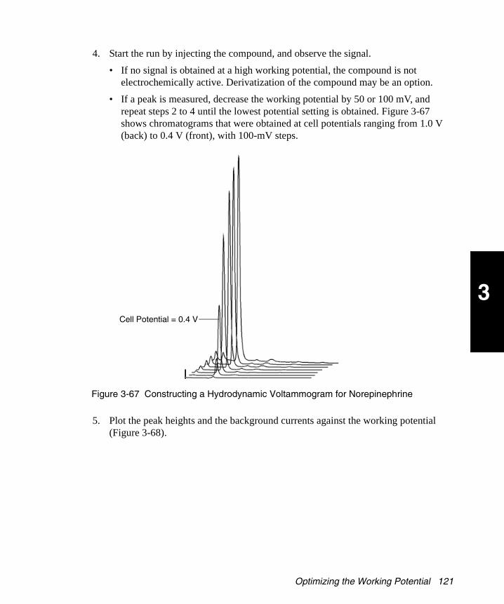
3
2465OG.book Page 121 Wednesday, November 7, 2007 10:33 AM
4. Start the run by injecting the compound, and observe the signal.
• If no signal is obtained at a high working potential, the compound is not electrochemically active. Derivatization of the compound may be an option.
• If a peak is measured, decrease the working potential by 50 or 100 mV, and repeat steps 2 to 4 until the lowest potential setting is obtained. Figure 3-67 shows chromatograms that were obtained at cell potentials ranging from 1.0 V (back) to 0.4 V (front), with 100-mV steps.
Figure 3-67 Constructing a Hydrodynamic Voltammogram for Norepinephrine
5. Plot the peak heights and the background currents against the working potential (Figure 3-68).
Cell Potential = 0.4 V
Optimizing the Working Potential 121

3
2465OG.book Page 122 Wednesday, November 7, 2007 10:33 AM
Figure 3-68 Scanning Voltammetry of Norepinephrine
Figure 3-68 shows the scanning voltammetry of 1.0 µM/L norepinephrine (scan A) at a glassy carbon WE, at a scan speed of 10 mV/s. Scan B is the blank solvent. Scan A is the sum of the analyte signal and the background signal.
6. Plot the signal-to-noise ratio against the working potential to obtain the working potential that gives the best sensitivity.
3.7.2 Constructing a Scanning Voltammogram
Use scan mode to program the Scan Setup screen (Figure 3-69).
Figure 3-69 Programming Scan Mode
Depending on your data acquisition software and experimental setup, you can select a half, full, or continuous scan cycle, as follows:
• Cyc=half – A half scan sweeps the potential from low (E1 = 0.20 V) to high (E2 = 1.20 V; see Figure 3-68 and Figure 3-70).
F1 F3 F5
122 Operating the 2465 Detector

3
2465OG.book Page 123 Wednesday, November 7, 2007 10:33 AM
• Cyc=full – A full scan includes the forward and reverse scans, i.e., from low (0.20 V) to high (1.20 V) and back to low.
• Cyc=cont – In the continuous scan cycle, the voltage is swept up and down continuously between the low and high potentials, E1 and E2.
Figure 3-70 shows the scanning voltammograms of 2,4-dimethylphenol (DMP), phenol (P), 2-chlorophenol (CP), 4-nitrophenol (NP), and a blank (buffer only).
Figure 3-70 Overlay of Four Half Forward Scans
To obtain a scanning voltammogram such as in Figure 3-68 and Figure 3-70:
1. Remove the column from the LC system and record the voltammogram in flow injection analysis (FIA) mode.
2. Perform an initial scan to assess the optimum start and stop times of the scan:
a. Dissolve the pure compound (preferably in the HPLC buffer) at a concentration of approximately 10 to 100 µM/L, then dilute it in HPLC buffer to the desired concentration.
b. Install an injection loop of 100 µL.
c. Set the LC flow rate at 40 µL/min.
d. Detect the analyte sample for approximately 2.5 minutes. Decrease the flow rate if more scanning time is needed.
3. Start an initial run in DC mode at a high potential to estimate the required start and stop time of the scan after sample injection (Figure 3-71).
Optimizing the Working Potential 123

3
2465OG.book Page 124 Wednesday, November 7, 2007 10:33 AM
In scan mode, the scan is obtained at the plateau of the analyte sample. In this example, scanning takes place on top of the broad peak between 0.4 and 2.4 minutes after injection in FIA mode.
Note: To prevent unreliable results, ensure that the analyte delivery is constant and without fluctuations.
Figure 3-71 Chromatogram of a Sample in DC Mode
4. Set the data rate of the integrator at 1 Hz. This is the same rate as the voltage steps during the scan. A higher rate might induce a typical stepwise pattern.
5. To set up the scan:
a. From the Main screen, select F4 SCAN. The Scan Setup screen appears (Figure 3-72).
Figure 3-72 Programming Scan Mode
b. Change the temperature if needed, and allow the detector to stabilize.
c. Select a lower potential (E1) and an upper potential (E2).
d. Set the range (Range) at 5 µA.
e. Leave the offset (Offs) at +10%.
F1 F3 F5
124 Operating the 2465 Detector
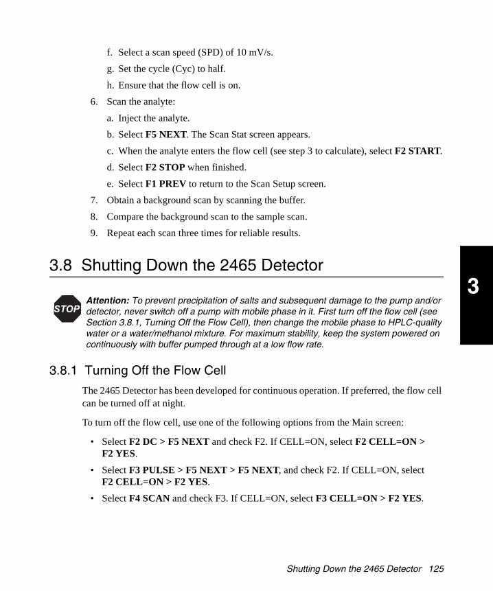
3
2465OG.book Page 125 Wednesday, November 7, 2007 10:33 AM
f. Select a scan speed (SPD) of 10 mV/s.
g. Set the cycle (Cyc) to half.
h. Ensure that the flow cell is on.
6. Scan the analyte:
a. Inject the analyte.
b. Select F5 NEXT. The Scan Stat screen appears.
c. When the analyte enters the flow cell (see step 3 to calculate), select F2 START.
d. Select F2 STOP when finished.
e. Select F1 PREV to return to the Scan Setup screen.
7. Obtain a background scan by scanning the buffer.
8. Compare the background scan to the sample scan.
9. Repeat each scan three times for reliable results.
3.8 Shutting Down the 2465 Detector
3.8.1 Turning Off the Flow Cell
The 2465 Detector has been developed for continuous operation. If preferred, the flow cell can be turned off at night.
To turn off the flow cell, use one of the following options from the Main screen:
• Select F2 DC > F5 NEXT and check F2. If CELL=ON, select F2 CELL=ON > F2 YES.
• Select F3 PULSE > F5 NEXT > F5 NEXT, and check F2. If CELL=ON, select F2 CELL=ON > F2 YES.
• Select F4 SCAN and check F3. If CELL=ON, select F3 CELL=ON > F2 YES.
Attention: To prevent precipitation of salts and subsequent damage to the pump and/or detector, never switch off a pump with mobile phase in it. First turn off the flow cell (see Section 3.8.1, Turning Off the Flow Cell), then change the mobile phase to HPLC-quality water or a water/methanol mixture. For maximum stability, keep the system powered on continuously with buffer pumped through at a low flow rate.
Shutting Down the 2465 Detector 125

3
2465OG.book Page 126 Wednesday, November 7, 2007 10:33 AM
3.8.2 Shutting Down for a Short Time
To shut down the detector on a routine basis (overnight or up to several days):
1. In the DC Stat, Pulse Stat, or Scan Stat screen, check the flow cell status. The flow cell can remain on if buffer or mobile phase is pumped continuously at a low flow rate, or you can turn off the flow cell (see Section 3.8.1, Turning Off the Flow Cell).
2. Recirculate the mobile phase.
3. Decrease the pump flow rate to approximately 10% of normal flow rate.
3.8.3 Shutting Down for a Long Time
To shut down the detector for a long time (weeks):
1. Turn off the flow cell (see Section 3.8.1, Turning Off the Flow Cell).
2. Flush the flow cell and column thoroughly with a 90:10 mixture of water:organic modifier (methanol or acetonitrile) to remove all traces of buffer salts. Do not leave the flow cell in water, but in a 90:10 mixture.
3. Store the column in methanol or acetonitrile, or according to the manufacturer’s instructions.
4. Clean and store the flow cell dry.
5. Power off the 2465 Detector by pressing the power switch on the rear panel.
Note: If you plan to restart the 2465 Detector after a long shutdown period, and a water/methanol mixture has been in the flow cell, Waters recommends that you polish the electrode before restarting the detector (see Section 4.5, Maintaining the Salt-Bridge Reference Electrode).
Attention: Keep the salt-bridge Ag/AgCl reference electrode soaking in a container with a saturated KCl solution.
126 Operating the 2465 Detector

4
2465OG.book Page 127 Wednesday, November 7, 2007 10:33 AM
Chapter 4 Maintaining the 2465 Detector
Use this chapter to maintain the electrodes and the 2465 Detector.
Note: For maximum stability, leave the system powered on continuously.
4.1 Introduction
Read the maintenance instructions before starting the procedures for the tasks in this chapter. If you are uncertain about how to perform the procedures, contact Waters Technical Service (see Section 4.1.4) to have a trained service representative perform the procedure.
4.1.1 General Safety Precautions
Perform periodic leak checks on the flow cell, LC tubing, and connections.
Do not close or block the waste drain.
Do not allow flammable and/or toxic solvents to accumulate. Follow a regulated, approved waste disposal program. Never dispose of such products through the municipal sewage system.
This instrument has a lithium battery. Only qualified service personnel should replace the battery. Dispose of the battery properly as chemical waste.
When you perform the maintenance procedures in this chapter on your 2465 Detector, follow these safety considerations.
Caution: Untrained personnel should not open the instrument. Removing protective panels on the instrument can result in exposure to potentially dangerous voltages. Disconnect the instrument from all power sources before maintenance.
Introduction 127

4
2465OG.book Page 128 Wednesday, November 7, 2007 10:33 AM
Caution: To prevent possible electrical shock, never disconnect an electrical assembly (including all interface cables) while power is applied to the detector.
Power off the detector before making any electrical connections. Power off the detector and disconnect the power cord before performing maintenance procedures.
Caution: When you handle solvents, change tubing, or operate the 2465 Detector in general, always observe good laboratory practices. Know the physical and chemical properties of the solvents. Refer to the Material Safety Data Sheets for the solvents in use.
Attention: To meet the regulatory requirements of immunity from external electrical disturbances that may affect the performance of this instrument, do not use cables longer than 9.8 feet (3 meters) when you make connections.
Attention: Before powering on the flow cell, ensure that:
The flow cell is filled with 20 to 100 mM electrolyte (buffer) that contains sufficient electrolyte (buffer ions). A flow cell filled with water is not adequate. A stable baseline will never be obtained if the cell is powered on with only water or another nonconducting mobile phase.
No air bubbles are trapped in the flow cell.
The outlet tubing from the flow cell leads to a waste container that is at a higher level than the flow cell. This ensures a minute backpressure, which prevents air-bubble entrapment. The outlet tubing should be under the liquid level to prevent electrical baseline noise.
Attention: To prevent substantial damage to the working electrode or electronics, never power on the flow cell when:
The cell cable is not correctly connected.
The cell is only partly (or not at all) filled with buffer (not HPLC water).
The outside of the flow cell is wet, particularly the part between the auxiliary and working electrode connection.
Attention: When connecting or disconnecting the flow cell cable, ensure the flow cell power is off (see Section 3.8.1, Turning Off the Flow Cell).
128 Maintaining the 2465 Detector

4
2465OG.book Page 129 Wednesday, November 7, 2007 10:33 AM
4.1.2 Frequency of Electrode Maintenance
Perform maintenance on the electrodes at the frequency in Table 4-1.
4.1.3 Spare Parts
Stock the recommended spare parts to minimize downtime (see Appendix B, 2465 Detector Components and Spare Parts). Appendix B lists all parts that you can replace. Parts not included in the list require replacement by a trained service representative.
4.1.4 Waters Technical Service
For problems with HPLC equipment, computer software, or hardware other than the 2465 Detector, consult the documentation or the manufacturer for the applicable instrument or program.
If you encounter a problem with the 2465 Detector that you cannot troubleshoot, contact Waters Technical Service at 800 252-4752, U.S. and Canadian customers only. Other customers, call your local Waters subsidiary or your local Waters Technical Service
Table 4-1 Schedule of Electrode Maintenance Tasks
Electrode Frequency Task
Salt-bridge (Ag/AgCl) reference electrode
Monthly Add saturated KCl or saturated NaCl solution and salt crystals to salt bridge.
Make sure no air bubbles are present.
Rarely, the cotton wool frit may need replacing.
Glassy carbon working electrode
Every 1 to 3 months
Polish the electrode and replace the spacer. Maintenance schedule depends on the application.
ISAAC reference electrode Every 3 months Polish, then coat with ISAAC solution. Replace the spacer.
Hydrogen reference electrode
As needed No maintenance is needed when used for carbohydrate analysis. If not in use, disassemble the flow cell and store the components dry (see Section 4.2, Disassembling the Flow Cell).
Auxiliary electrode As needed No maintenance is needed, except in PAD of carbohydrates.
Introduction 129

4
2465OG.book Page 130 Wednesday, November 7, 2007 10:33 AM
Representative, or call Waters corporate headquarters for assistance in Milford, Massachusetts (U.S.A.).
4.2 Disassembling the Flow Cell
Use this procedure for a standard flow cell with the Hy-REF electrode or ISAAC reference electrode. The flow cell is assembled properly when it arrives. The force on the bolts is preset to 30 Ncm.
To disassemble the flow cell:
1. Turn off the flow cell (see Section 3.8.1, Turning Off the Flow Cell).
2. Stop the HPLC pump.
3. Open the door, then disconnect the following from the flow cell (Figure 4-1):
• Inlet and outlet tubing
• All three ends of the flow cell cable
Caution: When you handle solvents, change tubing, or operate the 2465 Detector in general, always observe good laboratory practices. Know the physical and chemical properties of the solvents. Refer to the Material Safety Data Sheets for the solvents in use.
Attention: When connecting or disconnecting the flow cell cable, ensure the flow cell power is off.
130 Maintaining the 2465 Detector

4
2465OG.book Page 131 Wednesday, November 7, 2007 10:33 AM
Figure 4-1 Disconnecting the Flow Cell
4. Slide the flow cell upward or downward out of the clamp.
5. Remove the bolts from the flow cell using the hex key (Figure 4-2). The hex key is supplied in the flow cell startup kit.
Figure 4-2 Removing the Bolts (Top View)
6. Carefully pull the blocks apart and remove the spacer from the blocks.
Attention: To avoid damaging the flow cell, do not remove it by pulling it forcefully toward you.
Flow Cell Cable
Outlet Tubing
WE Block(Top)
Inlet Block
(Bottom)
Reference Electrode
Spacer
Inlet TubingWorking Electrode
AUX Electrode
Hex Bolts
WE Electrode
Outlet
AUX Electrode
Hex Bolts
Disassembling the Flow Cell 131

4
2465OG.book Page 132 Wednesday, November 7, 2007 10:33 AM
7. Continue with one of the following, as needed:
• Section 4.3, Cleaning the Working Electrode
• Section 4.4, Maintaining the ISAAC Reference Electrode
• Section 4.5, Maintaining the Salt-Bridge Reference Electrode
4.3 Cleaning the Working Electrode
Clean the glassy carbon (GC) or metal working electrodes (WEs) after prolonged use and whenever the flow cell sensitivity or performance markedly decreases. This may be due to fouling by oxidation (reduction) reaction products that cause electrochemical changes to the electrode surface. Excessively high currents also may change the electrode surface.
Note: In pulsed amperometric detection (PAD) mode using a gold or platinum WE, polishing is only needed in exceptional circumstances because the pulsation of potential continuously regenerates the electrode surface. Furthermore, the pulsing of the potential slowly consumes the metal of the electrode, so after prolonged use, the working electrode is below the surface level of the cell and cannot be polished at all. When this happens, replace the electrode block.
Caution: When you handle solvents, change tubing, or operate the 2465 Detector in general, always observe good laboratory practices. Know the physical and chemical properties of the solvents. Refer to the Material Safety Data Sheets for the solvents in use.
Attention: After prolonged use of the flow cell with a gold working electrode in pulse mode, the stainless steel AUX electrode acquires a yellowish sheen and the noise level increases. Polish the AUX electrode with steel wool regularly (every two months) to prevent these problems.
Avoid unnecessary polishing. Only polish the working electrode surface if the mirror-like finish cannot be restored by wiping the electrode surface with a tissue wet with ethanol.
Attention: Do not attempt to clean the metal (platinum, silver, or gold) working electrodes by pulsing. Instead, polish the working electrode as described in step 3 below.
Use a separate polishing cloth for each type of working electrode and for the ISAAC reference electrode.
132 Maintaining the 2465 Detector

4
2465OG.book Page 133 Wednesday, November 7, 2007 10:33 AM
To clean the working electrode:
1. For the glassy carbon working electrode only, use electrochemical cleaning (pulsing). In pulse mode, let the potential jump between +1 and –1 V for 10 minutes. Use the following settings:
• t1 = 1000 msec
• t2 = 1000 msec
• t3 = 0 msec
• E1 = +1 V
• E2 = –1 V
Note: If the glassy carbon working electrode is not clean, continue with step 2.
2. For platinum, silver, or gold working electrodes, clean the electrode surface:
a. Turn off the flow cell (see Section 3.8.1, Turning Off the Flow Cell).
b. Stop the HPLC pump.
c. Open the door, then remove and disassemble the flow cell (see Section 4.2, Disassembling the Flow Cell).
d. Wipe the electrode surface (in the top or WE block) with a tissue soaked with ethanol.
e. If it still looks stained, continue with step 3.
3. Polish the electrode surface as follows:
a. Shake the diamond slurry thoroughly before use.
b. Rinse the WE polishing disc with HPLC-grade water.
c. Apply a few drops of slurry on the wet polishing disc, and polish the electrode with a ‘figure 8’ motion for about 1 minute or less. Apply only gentle pressure.
d. Check the surface visually; repeat the procedure if necessary.
Attention: To prevent damage to the electrodes, do not use the same polishing disc for both the ISAAC reference electrode and the working electrode.
To prevent scratches on the WE, which can increase the noise levels, the WE polishing disc must not have any dust or other particles. This is because the diamond slurry has 1-µm particles and must not be contaminated with larger particles.
Cleaning the Working Electrode 133

4
2465OG.book Page 134 Wednesday, November 7, 2007 10:33 AM
4. After the WE is clean, reassemble the flow cell (see Section 4.6, Reassembling the Flow Cell). Use a new spacer.
5. Clean the WE polishing disc with HPLC-grade water and let it dry.
6. Store the dry WE polishing disc dust free in its plastic bag.
4.4 Maintaining the ISAAC Reference Electrode
The ISAAC reference electrode requires maintenance approximately once every three months. When the flow cell is opened to service the working electrode, the reference electrode should also be serviced.
4.4.1 Cleaning the ISAAC Reference Electrode
To clean the ISAAC reference electrode:
1. Turn off the flow cell (see Section 3.8.1, Turning Off the Flow Cell).
2. Stop the HPLC pump.
3. Open the door, then remove and disassemble the flow cell (see Section 4.2, Disassembling the Flow Cell). Figure 4-3 shows the location of the ISAAC reference electrode on the inlet block of the flow cell. This half of the flow cell only has a single electrical connector.
Figure 4-3 Locating the ISAAC Reference Electrode
Caution: When you handle solvents, change tubing, or operate the 2465 Detector in general, always observe good laboratory practices. Know the physical and chemical properties of the solvents. Refer to the Material Safety Data Sheets for the solvents in use.
Outer Pin of ISAAC Reference Electrode
Inner Surface of ISAAC Reference Electrode
Inlet Block
Inlet
134 Maintaining the 2465 Detector

4
2465OG.book Page 135 Wednesday, November 7, 2007 10:33 AM
Note: The polishing kit contains a bottle of diamond slurry and an ISAAC polishing disc specifically for the ISAAC electrode.
4. Gently polish the reference electrode surface as follows until the shining metal appears (Figure 4-4):
a. Shake the diamond slurry thoroughly before use.
b. If the bottle has not been opened, snip a small part of the top of the bottle.
c. Rinse the ISAAC polishing disc with HPLC-grade water thoroughly to remove any dust particles. Use several milliliters of water.
d. Apply one or two drops of slurry on the wetted polishing disc, and place the inner surface of the electrode block on the slurry.
e. Applying only gentle pressure, polish the electrode with a ‘figure 8’ motion for a few minutes (Figure 4-4) until the shiny silver surface appears. Do not press down; allow the weight of the block to do the work. If the brown coating remains, apply more pressure and repeat the polishing. If you cannot remove the coating, the electrode is below the surface of the block; replace the inlet block.
Figure 4-4 Polishing the ISAAC Reference Electrode
f. Clean the electrode with a wet tissue and check the surface visually.
g. If the metal surface does not shine, repeat the procedure until the shining metal surface appears.
Attention: To prevent damage to the electrodes, do not use the same polishing disc for both the ISAAC reference electrode and the working electrode.
Caution: The ISAAC reference electrode solution is corrosive. Handle with care. Refer to the Material Safety Data Sheets for the solvents in use.
Reference Electrode Surface
Diamond Slurry on Wet ISAAC
Polishing Disc
ISAAC Reference Electrode
Alignment Mark
Inlet Block
Maintaining the ISAAC Reference Electrode 135

4
2465OG.book Page 136 Wednesday, November 7, 2007 10:33 AM
5. Immediately after polishing, apply a few drops of the ISAAC reference electrode solution on the inner electrode surface to coat the electrode (Figure 4-5). After a few seconds, the electrode surface color changes.
Figure 4-5 Coating the ISAAC Reference Electrode
6. Clean the polishing disc with HPLC-grade water and let it dry, then store the ISAAC polishing disc dust free in its plastic bag.
7. After 20 minutes, thoroughly flush the surface of the electrode with HPLC-grade water to remove the reference solution.
8. Reassemble the flow cell using a new spacer (see Section 4.6, Reassembling the Flow Cell).
4.4.2 Storing the ISAAC Reference Electrode
To store the ISAAC reference electrode:
1. If not in use for a long time, disassemble the flow cell (see Section 4.2, Disassembling the Flow Cell).
2. Clean the flow cell including the reference electrode with HPLC-grade water.
3. Dry the flow cell with lint-free tissues and store it dry.
4.5 Maintaining the Salt-Bridge Reference Electrode
Three factors determine the proper functioning of the salt-bridge (SB) reference electrode:
• The chloride concentration must be kept at a strictly fixed level. This is best guaranteed by using a saturated chloride salt solution at a constant temperature.
Caution: When you handle solvents, change tubing, or operate the 2465 Detector in general, always observe good laboratory practices. Know the physical and chemical properties of the solvents. Refer to the Material Safety Data Sheets for the solvents in use.
Reference Electrode Solution
136 Maintaining the 2465 Detector

4
2465OG.book Page 137 Wednesday, November 7, 2007 10:33 AM
• The salt bridge must allow proper electrical contact with the mobile phase. The higher the leakage through the frit, the better the conductivity.
• Because of their extreme compressibility, air bubbles inside or close to the salt bridge will lead to instability of the three-electrode configuration and to changes in conductivity and the ionic equilibrium of the reference electrode. This increases the noise considerably.
4.5.1 Inspecting the Salt-Bridge Reference Electrode
After prolonged use, the salt bridge in the reference electrode becomes less than fully saturated, which usually leads to poor reproducibility in electrochemical detection. The potential of the reference electrode is determined by the chloride concentration. If the salt bridge is not saturated and the KCl concentration changes:
• The noise in the system slowly but continuously increases.
• The background current increases.
• Sensitivity to movements and pump noise increases.
To inspect the salt-bridge reference electrode:
1. Check the electrode regularly for air bubbles (Figure 4-6). If an air bubble is trapped in the salt bridge or in the cotton plug that separates the salt bridge and the mobile phase, the flow cell becomes extremely sensitive to flow fluctuations and vibrations. This is caused by the high compressibility of the trapped air.
Figure 4-6 Inspecting a Reference Electrode
Ag
AgCl
Saturated KClKCl Crystals
Cotton Wool Frit
Maintaining the Salt-Bridge Reference Electrode 137
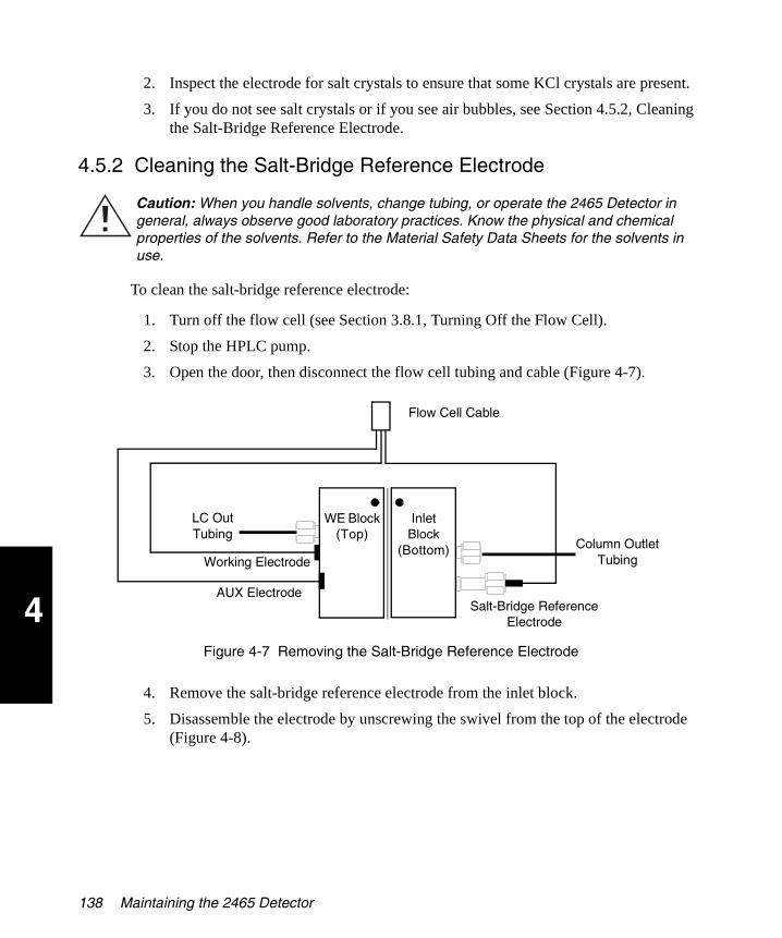
4
2465OG.book Page 138 Wednesday, November 7, 2007 10:33 AM
2. Inspect the electrode for salt crystals to ensure that some KCl crystals are present.
3. If you do not see salt crystals or if you see air bubbles, see Section 4.5.2, Cleaning the Salt-Bridge Reference Electrode.
4.5.2 Cleaning the Salt-Bridge Reference Electrode
To clean the salt-bridge reference electrode:
1. Turn off the flow cell (see Section 3.8.1, Turning Off the Flow Cell).
2. Stop the HPLC pump.
3. Open the door, then disconnect the flow cell tubing and cable (Figure 4-7).
Figure 4-7 Removing the Salt-Bridge Reference Electrode
4. Remove the salt-bridge reference electrode from the inlet block.
5. Disassemble the electrode by unscrewing the swivel from the top of the electrode (Figure 4-8).
Caution: When you handle solvents, change tubing, or operate the 2465 Detector in general, always observe good laboratory practices. Know the physical and chemical properties of the solvents. Refer to the Material Safety Data Sheets for the solvents in use.
Flow Cell Cable
LC Out Tubing
WE Block(Top)
Inlet Block
(Bottom)
Salt-Bridge Reference Electrode
Column Outlet TubingWorking Electrode
AUX Electrode
138 Maintaining the 2465 Detector

4
2465OG.book Page 139 Wednesday, November 7, 2007 10:33 AM
Figure 4-8 Components of the Salt-Bridge Reference Electrode
6. Remove the chloride solution from the salt bridge.
7. Clean all parts with HPLC-grade water.
8. If the silver on the tip of the Ag/AgCl electrode has a nonmetallic appearance, gently grind it on sanding paper.
9. Inspect the Viton® rings for wear and replace them if worn.
10. Examine the cotton wool frit in the salt bridge for discoloration and stains. If the frit is discolored or dried out, continue with Section 4.5.3, Replacing the Cotton Wool Frit.
If the frit is acceptable, continue with Section 4.5.4, Installing the Salt-Bridge Reference Electrode.
4.5.3 Replacing the Cotton Wool Frit
Required Materials
• An oversaturated and thoroughly degassed KCl solution
• A stainless steel rod of about 5-cm length and a diameter of 1 mm (a 1-mm drill); must be clean and free of contaminants such as oil or lubricant
• Clean, high-quality cotton wool
Procedure
To replace the cotton wool frit in the reference electrode:
1. If the reference electrode is new, remove the reference electrode cap.
Caution: When you handle solvents, change tubing, or operate the 2465 Detector in general, always observe good laboratory practices. Know the physical and chemical properties of the solvents. Refer to the Material Safety Data Sheets for the solvents in use.
Reference Electrode Cap
for Storage
Large Viton Ring
Salt Bridge
Small Viton Ring
Ag/AgCl Electrode and Fitting
Swivel for Reference Electrode
Tip of AgCl-Coated Silver Rod
Maintaining the Salt-Bridge Reference Electrode 139

4
2465OG.book Page 140 Wednesday, November 7, 2007 10:33 AM
2. Use a clean drill of 1 mm (0.039 inch) to push out the frit from the outside (Figure 4-9). Be careful not to damage the frit constriction.
Figure 4-9 Removing the Cotton Wool Frit
3. Soak a small piece of cotton wool in saturated KCl solution. Ensure that no air is trapped in the cotton wool.
4. Clean the salt bridge thoroughly by rinsing with tap water, then HPLC-grade water.
5. Fill the salt bridge half-full with saturated KCl solution.
6. Use the drill to pack the wool from above through the KCl solution into the channel of the salt bridge. Compress it firmly, but not too much.
7. Continue with Section 4.5.4, Installing the Salt-Bridge Reference Electrode.
4.5.4 Installing the Salt-Bridge Reference Electrode
To install the salt-bridge reference electrode:
1. Fill the salt bridge completely with KCl solution, and add some KCl crystals from a saturated solution to ensure prolonged saturation.
Caution: When you handle solvents, change tubing, or operate the 2465 Detector in general, always observe good laboratory practices. Know the physical and chemical properties of the solvents. Refer to the Material Safety Data Sheets for the solvents in use.
Drill (1 mmor 0.039 inch)
Cotton Wool Frit
Reference Electrode
Frit Constriction
140 Maintaining the 2465 Detector

4
2465OG.book Page 141 Wednesday, November 7, 2007 10:33 AM
2. Place the small Viton ring over the Ag/AgCl electrode and slowly insert it at an angle of 45° into the salt bridge. Make sure not to enclose an air bubble.
3. Tighten the black swivel of the reference electrode, but do not overtighten the swivel. A small droplet should appear at the cotton-wool frit.
Note: Do not remove this droplet because it ensures proper contact of the reference electrode with the mobile phase.
4. Turn on the HPLC pump. Keep some tissues at hand as some mobile phase probably will spill during this mounting procedure.
5. Connect the column outlet to the flow cell inlet using small-bore tubing (0.3-mm ID) and one fingertight fitting. Let the tubing protrude approximately 0.6 in (1.5 cm) from the fitting and tighten it such that the tubing is not indented or is slightly indented by the fitting.
6. Connect the medium-bore tubing (0.5-mm ID) to the outlet of the flow cell.
7. Fill the flow cell by keeping it in an angle of 45° with the reference electrode fitting on top. Block the outlet with a finger, and let the air escape at the reference electrode fitting. Carefully inspect the thread of the fitting for trapped air bubbles.
8. When the reference electrode fitting is completely filled with mobile phase, mount the reference electrode while slowly releasing the outlet. Make sure no air bubbles are visible.
9. Align the flow cell with the flow cell clamp, keeping the reference electrode at the lower side and the outlet (LC Out) uppermost to prevent trapping of air bubbles, then slide the flow cell into the clamp.
10. Connect the flow cell cable to the electrodes as follows (Figure 4-10):
• REF – Black wire to the reference electrode
• WE – Red wire to the working electrode
• AUX – Blue wire to the auxiliary electrode
Note: Do not power on the flow cell at this time.
Attention: Use only factory-supplied fingertight fittings in the flow cell. Do not overtighten the fitting. Overtightening affects the flow pattern through the tubing (turbulence) and might markedly decrease the flow cell performance.
Attention: To prevent damage to the flow cell, do not install it by pushing it forcefully into the clamp from the front.
Maintaining the Salt-Bridge Reference Electrode 141
4
2465OG.book Page 142 Wednesday, November 7, 2007 10:33 AM
4.5.5 Storing the Salt-Bridge Reference Electrode
When not in use, store the salt-bridge reference electrode with the cotton wool frit immersed in a saturated KCl solution to prevent drying out.
4.6 Reassembling the Flow Cell
Attention: Before powering on the flow cell, ensure that:
The flow cell is filled with 20 to 100 mM electrolyte (buffer) that contains sufficient electrolyte (buffer ions). A flow cell filled with water is not adequate. A stable baseline will never be obtained if the cell is powered on with only water or another nonconducting mobile phase.
No air bubbles are trapped in the flow cell.
The outlet tubing from the flow cell leads to a waste container that is at a higher level than the flow cell. This ensures a minute backpressure, which prevents air-bubble entrapment. The outlet tubing should be under the liquid level to prevent electrical baseline noise.
Attention: To prevent substantial damage to the working electrode or electronics, never power on the flow cell when:
The cell cable is not correctly connected.
The cell is only partly (or not at all) filled with buffer (not HPLC water).
The outside of the flow cell is wet, particularly the part between the auxiliary and working electrode connection.
Attention: When connecting or disconnecting the flow cell cable, ensure the flow cell power is off (see Section 3.8.1, Turning Off the Flow Cell).
Caution: When you handle solvents, change tubing, or operate the 2465 Detector in general, always observe good laboratory practices. Know the physical and chemical properties of the solvents. Refer to the Material Safety Data Sheets for the solvents in use.
142 Maintaining the 2465 Detector
4
2465OG.book Page 143 Wednesday, November 7, 2007 10:33 AM
Note: If you use the ISAAC reference electrode, add and equilibrate with chloride ions in the mobile phase before installing the electrode. Waters recommends 2 mM chloride ions.
Note: If you use the salt-bridge reference electrode, first connect the inlet and outlet, then fill the cell with mobile phase while keeping the REF hole on top (not the outlet hole). If the salt-bridge hole is filled with mobile phase, then the salt-bridge reference electrode is installed successfully without bubbles.
Note: Do not reuse the spacer; use a new spacer. Handle each spacer with care. Avoid wrinkles and folds, and make sure no dust or other particles are trapped. Make sure the flow cell surfaces are clean before reassembling the flow cell. Overtightening the bolts can cause excessive pressure in the flow cell and increase the noise considerably. To prevent overtightening, tighten the bolts until fingertight, then tighten them 1/4-turn more.
To reassemble the flow cell:
1. Make sure the flow cell blocks are clean and rinsed well with HPLC grade water, and that the four holes in the spacer line up with the four bolt holes in the flow cell block. Use a new spacer.
Note: The flow cell must contain a spacer. Do not reuse the spacer.
2. Align the top and bottom halves of the flow cell using the two black marker dots on the sides of the two flow cell electrode block halves.
3. Mount the two blocks together by tightening the four bolts (maximum torque 30 Ncm) using the hex key (see Figure 4-2). To prevent overtightening, tighten the bolts until fingertight, then tighten them 1/4-turn more.
4. Fill the flow cell with mobile phase, keeping it at an angle of about 45° with the outlet (LC out) on top to force the air through the outlet.
5. Connect the column outlet to the flow cell inlet using small-bore tubing (0.3-mm ID) and one fingertight fitting (Figure 4-10).
Attention: When connecting or disconnecting the flow cell cable, ensure the flow cell power is off.
To prevent deterioration of the S/N ratio and eventually the flow cell, do not overtighten the bolts. Also ensure that the black marks on both blocks line up before you insert and tighten the bolts. To prevent overtightening, loosen the bolts, tighten them until fingertight, then tighten them 1/4-turn more.
Reassembling the Flow Cell 143
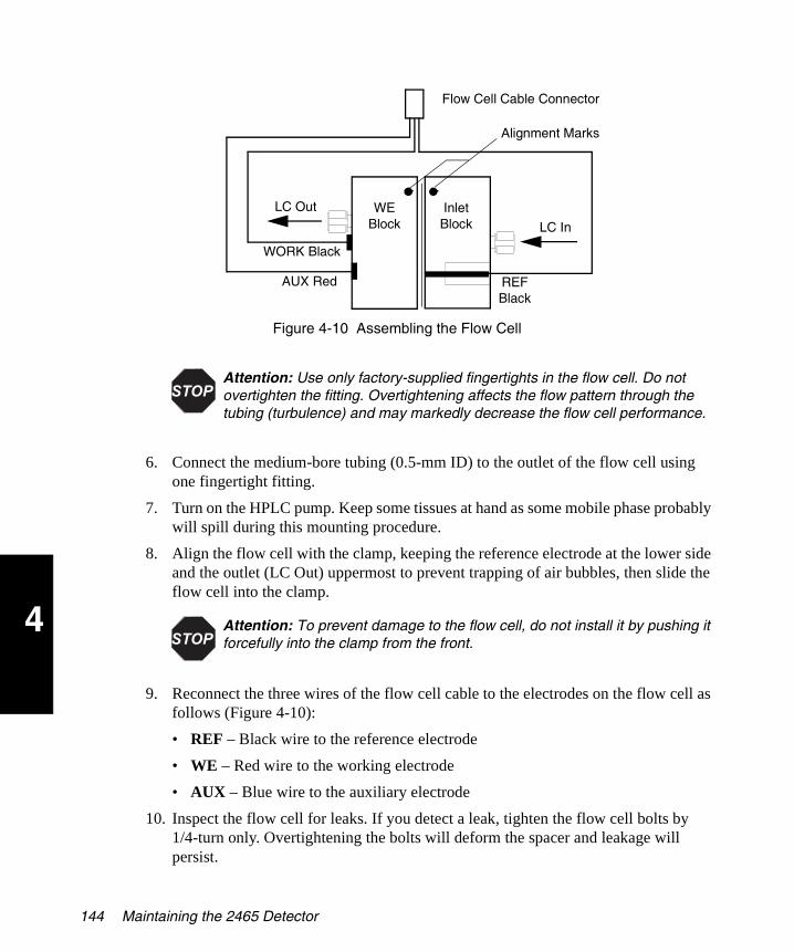
4
2465OG.book Page 144 Wednesday, November 7, 2007 10:33 AM
Figure 4-10 Assembling the Flow Cell
6. Connect the medium-bore tubing (0.5-mm ID) to the outlet of the flow cell using one fingertight fitting.
7. Turn on the HPLC pump. Keep some tissues at hand as some mobile phase probably will spill during this mounting procedure.
8. Align the flow cell with the clamp, keeping the reference electrode at the lower side and the outlet (LC Out) uppermost to prevent trapping of air bubbles, then slide the flow cell into the clamp.
9. Reconnect the three wires of the flow cell cable to the electrodes on the flow cell as follows (Figure 4-10):
• REF – Black wire to the reference electrode
• WE – Red wire to the working electrode
• AUX – Blue wire to the auxiliary electrode
10. Inspect the flow cell for leaks. If you detect a leak, tighten the flow cell bolts by 1/4-turn only. Overtightening the bolts will deform the spacer and leakage will persist.
Attention: Use only factory-supplied fingertights in the flow cell. Do not overtighten the fitting. Overtightening affects the flow pattern through the tubing (turbulence) and may markedly decrease the flow cell performance.
Attention: To prevent damage to the flow cell, do not install it by pushing it forcefully into the clamp from the front.
Flow Cell Cable Connector
LC In
LC Out WE Block
Inlet Block
REF Black
AUX Red
WORK Black
Alignment Marks
144 Maintaining the 2465 Detector
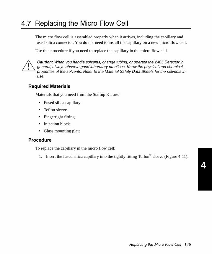
4
2465OG.book Page 145 Wednesday, November 7, 2007 10:33 AM
4.7 Replacing the Micro Flow Cell
The micro flow cell is assembled properly when it arrives, including the capillary and fused silica connector. You do not need to install the capillary on a new micro flow cell.
Use this procedure if you need to replace the capillary in the micro flow cell.
Required Materials
Materials that you need from the Startup Kit are:
• Fused silica capillary
• Teflon sleeve
• Fingertight fitting
• Injection block
• Glass mounting plate
Procedure
To replace the capillary in the micro flow cell:
1. Insert the fused silica capillary into the tightly fitting Teflon® sleeve (Figure 4-11).
Caution: When you handle solvents, change tubing, or operate the 2465 Detector in general, always observe good laboratory practices. Know the physical and chemical properties of the solvents. Refer to the Material Safety Data Sheets for the solvents in use.
Replacing the Micro Flow Cell 145

4
2465OG.book Page 146 Wednesday, November 7, 2007 10:33 AM
Figure 4-11 Mounting the Fused Silica Connector
2. Ensure that both the capillary and the sleeve protrude through the fingertight fitting.
3. Mount this combination carefully in the injection block. Let the fused silica protrude slightly (0.5 to 1 mm) through the injection hole.
4. Clean the glass mounting plate using ethanol or water.
5. Carefully push the block on the glass plate until the silica capillary is flush with the surface.
6. Fix the fused silica capillary firmly with the fingertight fitting while keeping a slight pressure of the block on the glass plate.
Fused Silica Capillary
Teflon Sleeve
Glass Mounting Plate
Fingertight Fitting
Injection Block
146 Maintaining the 2465 Detector
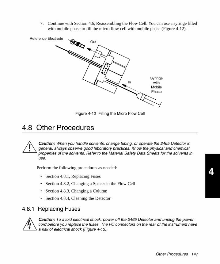
4
2465OG.book Page 147 Wednesday, November 7, 2007 10:33 AM
7. Continue with Section 4.6, Reassembling the Flow Cell. You can use a syringe filled with mobile phase to fill the micro flow cell with mobile phase (Figure 4-12).
Figure 4-12 Filling the Micro Flow Cell
4.8 Other Procedures
Perform the following procedures as needed:
• Section 4.8.1, Replacing Fuses
• Section 4.8.2, Changing a Spacer in the Flow Cell
• Section 4.8.3, Changing a Column
• Section 4.8.4, Cleaning the Detector
4.8.1 Replacing Fuses
Caution: When you handle solvents, change tubing, or operate the 2465 Detector in general, always observe good laboratory practices. Know the physical and chemical properties of the solvents. Refer to the Material Safety Data Sheets for the solvents in use.
Caution: To avoid electrical shock, power off the 2465 Detector and unplug the power cord before you replace the fuses. The I/O connectors on the rear of the instrument have a risk of electrical shock (Figure 4-13).
OutReference Electrode
InSyringe
with Mobile Phase
Other Procedures 147

4
2465OG.book Page 148 Wednesday, November 7, 2007 10:33 AM
Figure 4-13 I/O Connector Warning
Replace blown fuses with fuses of proper type and rating as stipulated on the rear panel. Use the correct fuses and power setting for your location (U.S.A. provides 110 V; your location may provide 240 V).
To replace the fuses:
1. Power off the 2465 Detector and remove the power cord.
2. Remove the fuse holder from the rear panel of the 2465 Detector (Figure 4-14).
Figure 4-14 Removing the Fuse Holder
3. Remove both fuses from the fuse holder.
4. Install two new fuses in the fuse holder, then install the fuse holder. Use only 5 × 20, 2.5-AT, 250 V fuses, as described on the rear panel (Figure 4-15).
Figure 4-15 Checking the Fuse Rating
Caution: Replace blown fuses with fuses of proper type and rating as stipulated on the rear panel. The fuse holder is integrated in the line connector.
To prevent the risk of fire, ensure that the instrument is never operated with the incorrect type of fuses.
AC Input Connector
Power Switch
148 Maintaining the 2465 Detector
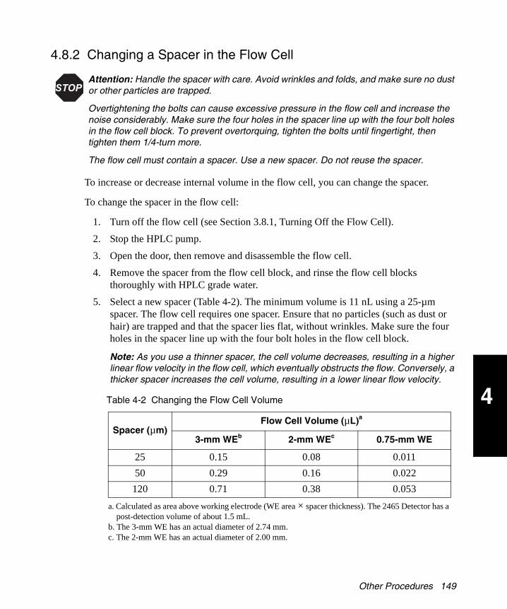
4
2465OG.book Page 149 Wednesday, November 7, 2007 10:33 AM
4.8.2 Changing a Spacer in the Flow Cell
To increase or decrease internal volume in the flow cell, you can change the spacer.
To change the spacer in the flow cell:
1. Turn off the flow cell (see Section 3.8.1, Turning Off the Flow Cell).
2. Stop the HPLC pump.
3. Open the door, then remove and disassemble the flow cell.
4. Remove the spacer from the flow cell block, and rinse the flow cell blocks thoroughly with HPLC grade water.
5. Select a new spacer (Table 4-2). The minimum volume is 11 nL using a 25-µm spacer. The flow cell requires one spacer. Ensure that no particles (such as dust or hair) are trapped and that the spacer lies flat, without wrinkles. Make sure the four holes in the spacer line up with the four bolt holes in the flow cell block.
Note: As you use a thinner spacer, the cell volume decreases, resulting in a higher linear flow velocity in the flow cell, which eventually obstructs the flow. Conversely, a thicker spacer increases the cell volume, resulting in a lower linear flow velocity.
Attention: Handle the spacer with care. Avoid wrinkles and folds, and make sure no dust or other particles are trapped.
Overtightening the bolts can cause excessive pressure in the flow cell and increase the noise considerably. Make sure the four holes in the spacer line up with the four bolt holes in the flow cell block. To prevent overtorquing, tighten the bolts until fingertight, then tighten them 1/4-turn more.
The flow cell must contain a spacer. Use a new spacer. Do not reuse the spacer.
Table 4-2 Changing the Flow Cell Volume
Spacer (µm)Flow Cell Volume (µL)a
a. Calculated as area above working electrode (WE area × spacer thickness). The 2465 Detector has a post-detection volume of about 1.5 mL.
3-mm WEb
b. The 3-mm WE has an actual diameter of 2.74 mm.
2-mm WEc
c. The 2-mm WE has an actual diameter of 2.00 mm.
0.75-mm WE
25 0.15 0.08 0.011
50 0.29 0.16 0.022
120 0.71 0.38 0.053
Other Procedures 149

4
2465OG.book Page 150 Wednesday, November 7, 2007 10:33 AM
6. Reassemble the flow cell (see Section 4.6, Reassembling the Flow Cell).
Note: To prevent overtightening, tighten the bolts until fingertight, then tighten them 1/4-turn more.
4.8.3 Changing a Column
To change a column:
1. Turn off the flow cell (see Section 3.8.1, Turning Off the Flow Cell).
2. Stop the HPLC pump.
3. Open the door.
4. Disconnect the tubing from the column.
5. Remove the column from the clamps and seal the ends.
6. Install a new, electrochemically clean column (see Section 2.4.2, Connecting a Column).
4.8.4 Cleaning the Detector
To clean the detector:
1. Disconnect the column and flow cell to remove them from the flow path.
2. Connect the tubing to make a continuous flow path to the waste container.
3. Flush the tubing by pumping water or ethanol through the lines for 30 minutes at 0.5 mL/min.
4. Wipe the outside and inside surfaces and keypad with water and lint-free tissues.
5. Empty and rinse the waste container, then reinstall it.
6. Remove any dust on the screens that cover the fans in the detector oven.
Caution: Do not allow flammable and/or toxic solvents to accumulate. Follow a regulated, approved waste disposal program. Never dispose of such products through the municipal sewage system.
Attention: To prevent permanent damage to the 2465 Detector, use only water to clean the detector.
150 Maintaining the 2465 Detector

5
2465OG.book Page 151 Wednesday, November 7, 2007 10:33 AM
Chapter 5 Diagnostics and Troubleshooting
Use this chapter to troubleshoot problems that you observe:
• Error messages – see Section 5.1
• Diagnostic tests – see Section 5.2
• Troubleshooting tables – see Section 5.3
– No detector response
– High cell current
– Noisy baseline
– Drifting baseline
– Decreased sensitivity (low S/N ratio)
– Baseline oscillations
– Saturation of output
• Other physical symptoms such as leaks – see Section 5.4
If there is a problem, contact Waters Technical Service (see Section 4.1.4).
Note: The current firmware version appears on the Main screen.
151

5
2465OG.book Page 152 Wednesday, November 7, 2007 10:33 AM
5.1 Error Messages
If an error message appears, see Table 5-1.
5.2 Diagnostics
You can use the following tests to diagnose problems with the 2465 Detector:
• Section 5.2.1, Dummy Cell Test
• Section 5.2.2, Stop Flow Test
• Section 5.2.3, Keyboard Test
• Section 5.2.4, Display Test
To access the Diagnostics tests, select F5 DIAG from the Main screen. The Diagnostics screen displays the names of the diagnostic tests (Figure 5-1).
Figure 5-1 Diagnostics Screen
5.2.1 Dummy Cell Test
A successful dummy cell test confirms that the 2465 Detector functions properly. If the result of the noise measurement with the dummy cell is within specification, the 2465 Detector is excluded as a cause of the problem.
Table 5-1 Error Messages
Message Solution
Out of Range May have exceeded maximum compensation, due to passthrough transient or to wrong range setting. If the wrong range was chosen, increment to the next available setting and see if the error persists. Repeat until an allowable range is reached.
Checksum Error Contact Waters Technical Service (see Section 4.1.4).
F1 F2 F3 F4 F5
152 Diagnostics and Troubleshooting

5
2465OG.book Page 153 Wednesday, November 7, 2007 10:33 AM
The dummy consists of a resistor (R) of 300 MΩ and a capacitor (C) of 0.47 µF in parallel. The current is measured over the resistor according to Ohm’s law:
V = I × R
where:
V = Voltage
I = Current
R = Resistance
With a working potential of 800 mV, the current drawn is 2.67 +0.05 nA. Slight differences to this value are due to the tolerance of the resistor. The capacitor functions as a ‘noise generator’ and in fact resembles the capacitance of a well-functioning standard flow cell in an ideal HPLC setup.
To perform the dummy cell test:
1. Turn off the flow cell and open the door.
2. Remove each end of the flow cell cable from the flow cell.
3. Attach cable ends from the flow cell cable to the dummy cell as in Figure 5-2 (red to red, blue to blue, and black to black). Keep the flow cell in the clamp and keep the large end of the flow cell cable attached to the 2465 Detector.
Figure 5-2 Dummy Cell
4. Ensure that the dummy cell is within the fully closed Faraday shield at the same position as the flow cell, and close the door.
5. Use the dummy cell test settings in Table 5-2.
Red
Blue
Black
Diagnostics 153

5
2465OG.book Page 154 Wednesday, November 7, 2007 10:33 AM
Note: Keep the door closed at all times during the test.
6. Stabilize the detector for at least 60 minutes.
7. Measure the output and cell potential values as follows:
a. From the Main screen, select F5 DIAG. The Diagnostics screen appears (Figure 5-3).
Figure 5-3 Diagnostics Screen
b. Select F2 NOISE. The Noise screen appears (Figure 5-4).
Figure 5-4 Noise Test with Dummy Cell
c. The clock on row 3 counts down for 5 minutes while the cell current stabilizes, then the output and cell potential values (read-out of the current) appear (Figure 5-5).
Table 5-2 Dummy Cell Test Settings
Parameter Setting
Cell potential 800 mV
Cell current 2.67 +0.05 nA (read-out)
Detector oven temperature 30 °C, stable
Filter time constant 1.0 sec (or as specified)
Range 100 pA/Va
a. Using these settings, the results of the output voltage (highest noise peak) should be no greater than 20 mV at Integrator Out.
F1 F2 F3 F4 F5
F1
154 Diagnostics and Troubleshooting

5
2465OG.book Page 155 Wednesday, November 7, 2007 10:33 AM
Figure 5-5 Noise Test Screen
d. The value of Ic should be 2.67 + 0.05 nA.
e. Select F1 PREV > F1 PREV to return to the Main screen.
8. Measure the noise. The noise generated during the test should be less than 2 pA.
5.2.2 Stop Flow Test
The 2465 Detector can detect noise but often is not the cause of the noise. Use the stop flow test to isolate the origin of excessive noise, which can be caused by:
• High background current
• Improper grounding
• External instruments, pumps, and so on
• Poor conductivity mobile phase
High background is the most common problem. This can be caused by:
• Potential setting too high.
• Contaminated mobile phase from a bleeding column or a high amount of unchelated iron ions (Fe++) in the mobile phase.
• Concentration of oxygen in the mobile phase too high.
In the stop flow test:
1. Read the cell current with the flow on.
2. Switch off the flow from the LC system.
3. Read the cell current with the flow off.
4. If the cell current drops significantly (for example, from 500 to 150 nA), then the mobile phase might be contaminated, or the column might be bleeding.
Note: Contamination can enter the mobile phase from several places, including the column. Contamination does not necessarily originate in the mobile phase bottle.
F1
Diagnostics 155

5
2465OG.book Page 156 Wednesday, November 7, 2007 10:33 AM
5. Replace the mobile phase and repeat the stop flow test.
6. If the problem continues, the column may be the source. To ensure a column is electrochemically clean, allow three days of low-flow solvent.
Alternatively, the column may need replacing. Ensure that the new column is electrochemically clean (see Section 3.3, Preparing the 2465 Detector for Operation).
5.2.3 Keyboard Test
Use the keyboard test to verify that the keys on the keypad work correctly.
To perform the keyboard test:
1. From the Main screen, select F5 DIAG. The Diagnostics screen appears.
2. Select F3 KEYB.
3. Press the F1 key on the keypad. Figure 5-6 appears if the key is working correctly, then disappears after a few seconds.
Figure 5-6 Testing a Key on the Keypad
4. Select each key until you have tested all 12 keys.
5. Select F1 PREV twice (rapidly) to return to the Diagnostics screen.
6. If there is a problem, contact Waters Technical Service (see Section 4.1.4).
5.2.4 Display Test
Use the display test to verify that all pixels in the 4 × 40 LCD display work correctly.
To perform the Display test:
1. From the Main screen, select F5 DIAG. The Diagnostics screen appears.
2. Select F4 DISPL. The Display screen appears (Figure 5-7). All characters on the display should be solid black except the screen name (DISP) and the F1 PREV key.
F1
156 Diagnostics and Troubleshooting
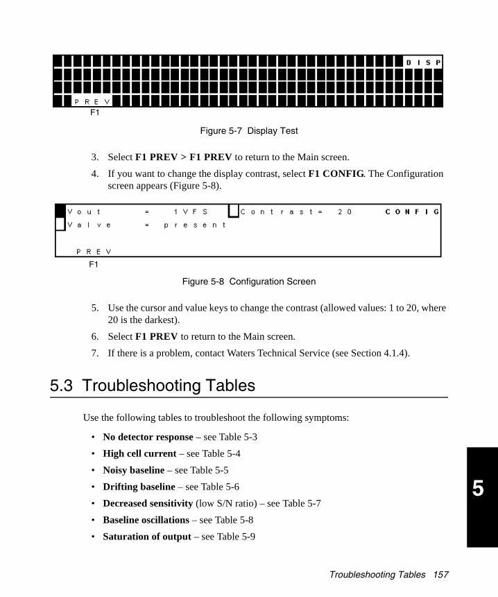
5
2465OG.book Page 157 Wednesday, November 7, 2007 10:33 AM
Figure 5-7 Display Test
3. Select F1 PREV > F1 PREV to return to the Main screen.
4. If you want to change the display contrast, select F1 CONFIG. The Configuration screen appears (Figure 5-8).
Figure 5-8 Configuration Screen
5. Use the cursor and value keys to change the contrast (allowed values: 1 to 20, where 20 is the darkest).
6. Select F1 PREV to return to the Main screen.
7. If there is a problem, contact Waters Technical Service (see Section 4.1.4).
5.3 Troubleshooting Tables
Use the following tables to troubleshoot the following symptoms:
• No detector response – see Table 5-3
• High cell current – see Table 5-4
• Noisy baseline – see Table 5-5
• Drifting baseline – see Table 5-6
• Decreased sensitivity (low S/N ratio) – see Table 5-7
• Baseline oscillations – see Table 5-8
• Saturation of output – see Table 5-9
F1
F1
Troubleshooting Tables 157

5
2465OG.book Page 158 Wednesday, November 7, 2007 10:33 AM
Table 5-3 No Detector Response
Possible Cause Remedy
No power Check line voltage for local power outage.
Ensure that power cord is plugged in correctly.
Power switch off Turn the power switch on (at the rear panel).
Faulty or blown detector fuse
Replace detector fuse.
Flow cell disconnected or switched off
Check connections, especially flow cell cable.
Check DC Stat or Pulse Stat screen to see if flow cell is on.
Recorder/integrator disconnected
Check cable connections.
Fouled working electrode Clean electrode.
Under Empower control Check Empower status (see Section 3.2.4, Remote Mode).
Table 5-4 High Cell Current
Possible Cause Remedy
Contaminated buffer Replace buffer. Do not recycle the buffer.
High working electrode potential
Optimize potential, if possible, by using a smaller working electrode diameter.
Salt bridge in reference electrode not saturated
Refill salt bridge with wet KCl crystals.
Retained peaks from previous runs
Wait for elution of these (very) broad peaks.
Column is ‘bleeding’ Ensure the column is electrochemically clean (see Section 2.4.2, Connecting a Column).
If column continues to bleed, replace the column with an electrochemically clean column.
High amount of Fe++ in buffer
Add EDTA to buffer; rinse metal parts with 15% HNO3.
158 Diagnostics and Troubleshooting
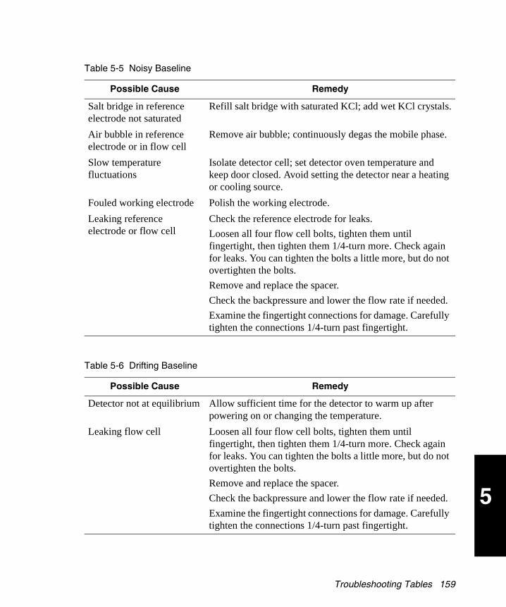
5
2465OG.book Page 159 Wednesday, November 7, 2007 10:33 AM
Table 5-5 Noisy Baseline
Possible Cause Remedy
Salt bridge in reference electrode not saturated
Refill salt bridge with saturated KCl; add wet KCl crystals.
Air bubble in reference electrode or in flow cell
Remove air bubble; continuously degas the mobile phase.
Slow temperature fluctuations
Isolate detector cell; set detector oven temperature and keep door closed. Avoid setting the detector near a heating or cooling source.
Fouled working electrode Polish the working electrode.
Leaking reference electrode or flow cell
Check the reference electrode for leaks.
Loosen all four flow cell bolts, tighten them until fingertight, then tighten them 1/4-turn more. Check again for leaks. You can tighten the bolts a little more, but do not overtighten the bolts.
Remove and replace the spacer.
Check the backpressure and lower the flow rate if needed.
Examine the fingertight connections for damage. Carefully tighten the connections 1/4-turn past fingertight.
Table 5-6 Drifting Baseline
Possible Cause Remedy
Detector not at equilibrium Allow sufficient time for the detector to warm up after powering on or changing the temperature.
Leaking flow cell Loosen all four flow cell bolts, tighten them until fingertight, then tighten them 1/4-turn more. Check again for leaks. You can tighten the bolts a little more, but do not overtighten the bolts.
Remove and replace the spacer.
Check the backpressure and lower the flow rate if needed.
Examine the fingertight connections for damage. Carefully tighten the connections 1/4-turn past fingertight.
Troubleshooting Tables 159
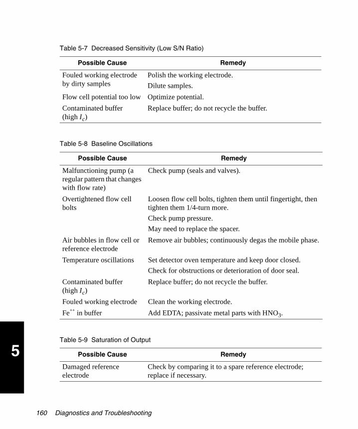
5
2465OG.book Page 160 Wednesday, November 7, 2007 10:33 AM
Table 5-7 Decreased Sensitivity (Low S/N Ratio)
Possible Cause Remedy
Fouled working electrode by dirty samples
Polish the working electrode.
Dilute samples.
Flow cell potential too low Optimize potential.
Contaminated buffer (high Ic)
Replace buffer; do not recycle the buffer.
Table 5-8 Baseline Oscillations
Possible Cause Remedy
Malfunctioning pump (a regular pattern that changes with flow rate)
Check pump (seals and valves).
Overtightened flow cell bolts
Loosen flow cell bolts, tighten them until fingertight, then tighten them 1/4-turn more.
Check pump pressure.
May need to replace the spacer.
Air bubbles in flow cell or reference electrode
Remove air bubbles; continuously degas the mobile phase.
Temperature oscillations Set detector oven temperature and keep door closed.
Check for obstructions or deterioration of door seal.
Contaminated buffer (high Ic)
Replace buffer; do not recycle the buffer.
Fouled working electrode Clean the working electrode.
Fe++ in buffer Add EDTA; passivate metal parts with HNO3.
Table 5-9 Saturation of Output
Possible Cause Remedy
Damaged reference electrode
Check by comparing it to a spare reference electrode; replace if necessary.
160 Diagnostics and Troubleshooting

5
2465OG.book Page 161 Wednesday, November 7, 2007 10:33 AM
5.4 Physical Symptoms
Table 5-10 lists other symptoms you may need to diagnose and repair.
Damaged working electrode
Replace flow cell block.
Flow cell incorrectly connected
Check connections of flow cell cable (REF – black, WE – red, AUX – blue).
Flow cell potential too high Optimize flow cell potential.
Table 5-10 Physical Symptoms
Symptom Possible Cause and Remedy
Fluid leaks Flow cell is leaking due to:
• Improper assembly (wrinkled spacer, or dirt or hair between spacer and block).
• Overtightening of the flow cell bolts.
Loosen all four flow cell bolts, tighten them until fingertight, then tighten them 1/4-turn more. Check again for leaks. You can tighten the bolts a little more. Do not overtighten the bolts.
Remove and replace the spacer.
Check the backpressure and lower the flow rate if needed.
Examine the fingertight connections for damage. Carefully tighten the connections 1/4-turn past fingertight.
Check the reference electrode for leaks.
Check for and fix tubing splitting at connections, tubing loose or falling off, problems with the fingertight fittings, or bent tubing.
Check fluid pressure to see if it exceeds recommendations (maximum 40 psi), then look for blockages in tubing or flow cell.
No LCD or Incorrect LCD
Reading wrong character or missing letter or all black due to broken crystals (see Section 5.2.4, Display Test).
Table 5-9 Saturation of Output (Continued)
Possible Cause Remedy
Physical Symptoms 161
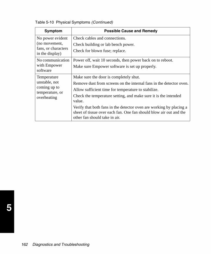
5
2465OG.book Page 162 Wednesday, November 7, 2007 10:33 AM
No power evident (no movement, fans, or characters in the display)
Check cables and connections.
Check building or lab bench power.
Check for blown fuse; replace.
No communication with Empower software
Power off, wait 10 seconds, then power back on to reboot.
Make sure Empower software is set up properly.
Temperature unstable, not coming up to temperature, or overheating
Make sure the door is completely shut.
Remove dust from screens on the internal fans in the detector oven.
Allow sufficient time for temperature to stabilize.
Check the temperature setting, and make sure it is the intended value.
Verify that both fans in the detector oven are working by placing a sheet of tissue over each fan. One fan should blow air out and the other fan should take in air.
Table 5-10 Physical Symptoms (Continued)
Symptom Possible Cause and Remedy
162 Diagnostics and Troubleshooting
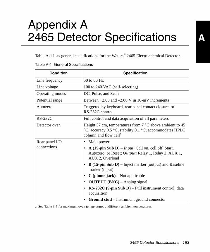
A
2465OG.book Page 163 Wednesday, November 7, 2007 10:33 AM
Appendix A 2465 Detector Specifications
Table A-1 lists general specifications for the Waters® 2465 Electrochemical Detector.
Table A-1 General Specifications
Condition Specification
Line frequency 50 to 60 Hz
Line voltage 100 to 240 VAC (self-selecting)
Operating modes DC, Pulse, and Scan
Potential range Between +2.00 and –2.00 V in 10-mV increments
Autozero Triggered by keyboard, rear panel contact closure, or RS-232C control
RS-232C Full control and data acquisition of all parameters
Detector oven Height 37 cm, temperatures from 7 °C above ambient to 45 °C, accuracy 0.5 °C, stability 0.1 °C; accommodates HPLC column and flow cella
a. See Table 3-5 for maximum oven temperatures at different ambient temperatures.
Rear panel I/O connections
• Main power
• A (15-pin Sub D) – Input: Cell on, cell off, Start, Autozero, or Reset; Output: Relay 1, Relay 2, AUX 1, AUX 2, Overload
• B (15-pin Sub D) – Inject marker (output) and Baseline marker (input)
• C (phone jack) – Not applicable
• OUTPUT (BNC) – Analog signal
• RS-232C (9-pin Sub D) – Full instrument control; data acquisition
• Ground stud – Instrument ground connector
2465 Detector Specifications 163

A
2465OG.book Page 164 Wednesday, November 7, 2007 10:33 AM
Table A-2 Physical Specifications
Condition Specification
Height 17.3 inches (44 cm)
Length (Depth) 17.3 inches (44 cm)
Width 8.7 inches (22 cm)
Weight 30.9 lb (14 kg) without flow cell and column
Table A-3 Operating and Environmental Requirements
Parameter Requirement
Operating temperature range 39 to 104 °F (4 to 40 °C)
Storage temperature range –104 to 158 °F (–40 to 70 °C)
Relative humidity range 20 to 80%, noncondensing
Storage humidity range 0 to 90%, noncondensing
Bench space 6 in (15.25 cm) clearance at rear; access to power switch and power cord; clean, level, smooth surface
Vibration Negligible
Static electricity Negligible
Power Grounded AC, 100 to 240 VAC, 50/60 Hz
Table A-4 DC Mode
Condition Specification
Current ranges, recorder 10 pA to 200 µA in 1, 2, or 5 steps
Filter (time constants) 0.1 to 5 sec in 1, 2, or 5 steps
Noise < 2 pA with a dummy cell using 100 pA range (load of 300 MΩ and 0.5 µF) with 1.0 sec filter
164 2465 Detector Specifications

A
2465OG.book Page 165 Wednesday, November 7, 2007 10:33 AM
Table A-5 Pulse Mode
Condition Specification
Range 10 nA to 200 µA in 1, 2, 5 steps
Pulse times t1: 100 to 2000 ms t2: 0 (off) to 2000 ms t3: 0 (off) to 2000 ms in 10-ms steps
Sample times 20, 40, 60, 80, and 100 ms
Table A-6 Scan Mode
Condition Specification
Range 10 nA to 200 µA in 1, 2, or 5 steps
Scan rate 1 to 50 mV/s in 1, 2, or 5 steps
Cycle Half, full, or continuous
Start/Stop, Hold and Autozero, Starting potential (E1), End potential (E2)
Table A-7 Timed Events Mode
Condition Specification
Parameters DC mode (5 files) and pulse mode (4 files), cycles
Control Time-based control of 50 timed events. Controllable parameters: range, filter, cell potential (Ec), Polarity, Autozero, Offset, and Outputs (2 TTL open collector, 2 relays).
Table A-8 Flow Cell Specifications
Component Specification
Design Confined wall-jet design; working volume determined by spacer thickness and WE diameter
Spacers 25, 50, or 120 µm
WE diameters 2.00 and 2.74 mm (0.75 mm with micro flow cell)
2465 Detector Specifications 165
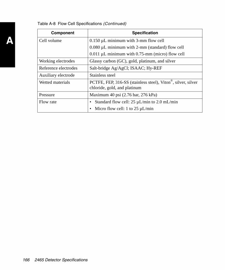
A
2465OG.book Page 166 Wednesday, November 7, 2007 10:33 AM
Cell volume 0.150 µL minimum with 3-mm flow cell
0.080 µL minimum with 2-mm (standard) flow cell
0.011 µL minimum with 0.75-mm (micro) flow cell
Working electrodes Glassy carbon (GC), gold, platinum, and silver
Reference electrodes Salt-bridge Ag/AgCl; ISAAC; Hy-REF
Auxiliary electrode Stainless steel
Wetted materials PCTFE, FEP, 316-SS (stainless steel), Viton®, silver, silver chloride, gold, and platinum
Pressure Maximum 40 psi (2.76 bar, 276 kPa)
Flow rate • Standard flow cell: 25 µL/min to 2.0 mL/min
• Micro flow cell: 1 to 25 µL/min
Table A-8 Flow Cell Specifications (Continued)
Component Specification
166 2465 Detector Specifications

B
2465OG.book Page 167 Wednesday, November 7, 2007 10:33 AM
Appendix B 2465 Detector Components and Spare Parts
The initial shipment of the Waters 2465 Electrochemical Detector contains:
• Waters 2465 Electrochemical Detector (without flow cell or column)
• Power cable
• Startup Kit (see Table B-8)
A flow cell must be ordered separately.
B.1 Flow Cells
You can order the flow cells listed in Table B-1 for the 2465 Detector.
Note: A flow cell, such as the glassy carbon (GC) WE ISAAC flow cell, must be ordered separately (see Table B-2 through Table B-7).
Table B-1 Flow Cell Kits
Waters Part Number
ComponentActual WE Diameter
205004115 Flow cell with 2-mm glassy carbon (GC) WE, salt-bridge reference electrode (see Table B-2)
2.00 mm
205004215 Flow cell with 2-mm glassy carbon (GC) WE, ISAAC reference electrode (see Table B-3)
2.00 mm
205004315 Flow cell with 2-mm glassy carbon (GC) WE, Hy-REF electrode
2.00 mm
205004320 Flow cell with 3-mm platinum (Pt) WE, Hy-REF electrode
2.74 mm
205004325 Flow cell with 3-mm gold (Au) WE, Hy-REF electrode (see Table B-5)
2.74 mm
2465 Detector Components and Spare Parts 167
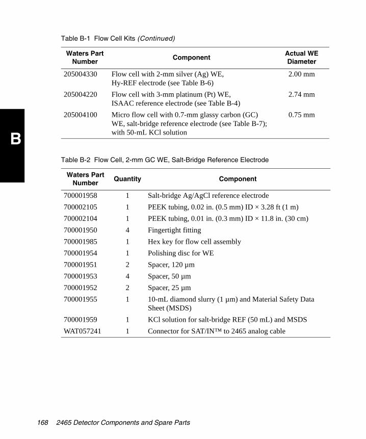
B
2465OG.book Page 168 Wednesday, November 7, 2007 10:33 AM
205004330 Flow cell with 2-mm silver (Ag) WE, Hy-REF electrode (see Table B-6)
2.00 mm
205004220 Flow cell with 3-mm platinum (Pt) WE, ISAAC reference electrode (see Table B-4)
2.74 mm
205004100 Micro flow cell with 0.7-mm glassy carbon (GC) WE, salt-bridge reference electrode (see Table B-7); with 50-mL KCl solution
0.75 mm
Table B-2 Flow Cell, 2-mm GC WE, Salt-Bridge Reference Electrode
Waters Part Number
Quantity Component
700001958 1 Salt-bridge Ag/AgCl reference electrode
700002105 1 PEEK tubing, 0.02 in. (0.5 mm) ID × 3.28 ft (1 m)
700002104 1 PEEK tubing, 0.01 in. (0.3 mm) ID × 11.8 in. (30 cm)
700001950 4 Fingertight fitting
700001985 1 Hex key for flow cell assembly
700001954 1 Polishing disc for WE
700001951 2 Spacer, 120 µm
700001953 4 Spacer, 50 µm
700001952 2 Spacer, 25 µm
700001955 1 10-mL diamond slurry (1 µm) and Material Safety Data Sheet (MSDS)
700001959 1 KCl solution for salt-bridge REF (50 mL) and MSDS
WAT057241 1 Connector for SAT/IN™ to 2465 analog cable
Table B-1 Flow Cell Kits (Continued)
Waters Part Number
ComponentActual WE Diameter
168 2465 Detector Components and Spare Parts

B
2465OG.book Page 169 Wednesday, November 7, 2007 10:33 AM
Table B-3 Flow Cell, 2-mm GC WE, ISAAC Reference Electrode
Waters Part Number
Quantity Component
N/A 1 Glassy carbon working electrode, ISAAC reference electrode
700002105 1 PEEK tubing, 0.02 in. (0.5 mm) ID × 3.28 ft (1 m)
700002104 1 PEEK tubing, 0.01 in. (0.3 mm) ID × 11.8 in. (30 cm)
700001950 4 Fingertight fitting
700001985 1 Hex key for flow cell assembly
700001954 1 Polishing disc for WE
700002069 1 Polishing disc for REF
700001951 2 Spacer, 120 µm
700001953 4 Spacer, 50 µm
700001952 2 Spacer, 25 µm
700001955 1 10-mL diamond slurry (1 µm) and Material Safety Data Sheet (MSDS)
700001949 1 ISAAC solution for ISAAC reference (10 mL) and MSDS
Table B-4 Flow Cell, 3-mm Pt WE, ISAAC Reference Electrode
Waters Part Number
Quantity Component
N/A 1 Platinum working electrode, ISAAC reference electrode
700002105 1 PEEK tubing, 0.02 in. (0.5 mm) ID × 3.28 ft (1 m)
700002104 1 PEEK tubing, 0.01 in. (0.3 mm) ID × 11.8 in. (30 cm)
700001950 4 Fingertight fitting
700001985 1 Hex key for flow cell assembly
700001954 1 Polishing disc for WE
700002069 1 Polishing disc for REF
700001951 2 Spacer, 120 µm
700001953 4 Spacer, 50 µm
700001952 2 Spacer, 25 µm
2465 Detector Components and Spare Parts 169

B
2465OG.book Page 170 Wednesday, November 7, 2007 10:33 AM
700001955 1 10-mL diamond slurry (1 µm) and Material Safety Data Sheet (MSDS)
700001949 1 ISAAC solution (10 mL) and MSDS
Table B-5 Flow Cell, 3-mm Au WE, Hy-REF Electrode
Waters Part Number
Quantity Component
N/A 1 Gold working electrode, Hy-REF electrode
700002105 1 PEEK tubing, 0.02 in. (0.5 mm) ID × 3.28 ft (1 m)
700002104 1 PEEK tubing, 0.01 in. (0.3 mm) ID × 11.8 in. (30 cm)
700001950 4 Fingertight fitting
700001985 1 Hex key for flow cell assembly
700001954 1 Polishing disc for WE
700002069 1 Polishing disc for REF
700001951 2 Spacer, 120 µm
700001953 4 Spacer, 50 µm
700001952 2 Spacer, 25 µm
700001955 1 10-mL diamond slurry (1 µm) and Material Safety Data Sheet (MSDS)
Table B-6 Flow Cell, 2-mm Ag WE, Hy-REF Electrode
Waters Part Number
Quantity Component
N/A 1 Silver working electrode, Hy-REF electrode
700002105 1 PEEK tubing, 0.02 in. (0.5 mm) ID × 3.28 ft (1 m)
700002104 1 PEEK tubing, 0.01 in. (0.3 mm) ID × 11.8 in. (30 cm)
700001950 4 Fingertight fitting
700001985 1 Hex key for flow cell assembly
Table B-4 Flow Cell, 3-mm Pt WE, ISAAC Reference Electrode (Continued)
Waters Part Number
Quantity Component
170 2465 Detector Components and Spare Parts

B
2465OG.book Page 171 Wednesday, November 7, 2007 10:33 AM
700001954 1 Polishing disc for WE
700002069 1 Polishing disc for REF
700001951 2 Spacer, 120 µm
700001953 4 Spacer, 50 µm
700001952 2 Spacer, 25 µm
700001955 1 10-mL diamond slurry (1 µm) and Material Safety Data Sheet (MSDS)
Table B-7 Micro Flow Cell, 0.7-mm GC WE, Salt-Bridge REF Electrode
Waters Part Number
Quantity Component
N/A 1 Micro flow cell, glassy carbon working electrode, salt-bridge reference electrode
700002105 1 PEEK tubing, 0.02 in. (0.5 mm) ID × 3.28 ft (1 m)
700002104 1 PEEK tubing, 0.01 in. (0.3 mm) ID × 11.8 in. (30 cm)
700001950 4 Fingertight fitting
700001985 1 Hex key for flow cell assembly
700001954 1 Polishing disc for WE
700001951 2 Spacer, 120 µm
700001953 4 Spacer, 50 µm
700001952 2 Spacer, 25 µm
700001955 1 10-mL diamond slurry (1 µm) and Material Safety Data Sheet (MSDS)
700001958 1 Salt-bridge Ag/AgCl reference electrode
700001959 1 KCl solution for salt-bridge REF (50 mL) and MSDS
700002103 1 Capillary flow cell and glass plate for mounting capillary tubing connection
Table B-6 Flow Cell, 2-mm Ag WE, Hy-REF Electrode (Continued)
Waters Part Number
Quantity Component
2465 Detector Components and Spare Parts 171
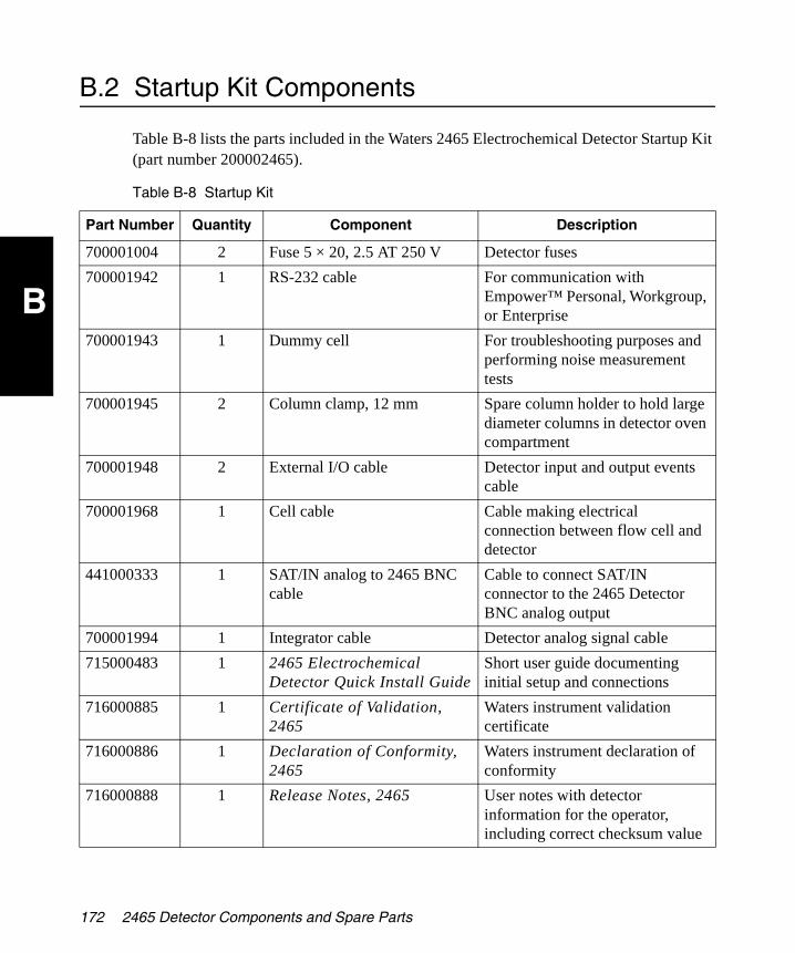
B
2465OG.book Page 172 Wednesday, November 7, 2007 10:33 AM
B.2 Startup Kit Components
Table B-8 lists the parts included in the Waters 2465 Electrochemical Detector Startup Kit (part number 200002465).
Table B-8 Startup Kit
Part Number Quantity Component Description
700001004 2 Fuse 5 × 20, 2.5 AT 250 V Detector fuses
700001942 1 RS-232 cable For communication with Empower™ Personal, Workgroup, or Enterprise
700001943 1 Dummy cell For troubleshooting purposes and performing noise measurement tests
700001945 2 Column clamp, 12 mm Spare column holder to hold large diameter columns in detector oven compartment
700001948 2 External I/O cable Detector input and output events cable
700001968 1 Cell cable Cable making electrical connection between flow cell and detector
441000333 1 SAT/IN analog to 2465 BNC cable
Cable to connect SAT/IN connector to the 2465 Detector BNC analog output
700001994 1 Integrator cable Detector analog signal cable
715000483 1 2465 Electrochemical Detector Quick Install Guide
Short user guide documenting initial setup and connections
716000885 1 Certificate of Validation, 2465
Waters instrument validation certificate
716000886 1 Declaration of Conformity, 2465
Waters instrument declaration of conformity
716000888 1 Release Notes, 2465 User notes with detector information for the operator, including correct checksum value
172 2465 Detector Components and Spare Parts

B
2465OG.book Page 173 Wednesday, November 7, 2007 10:33 AM
B.3 Spare Parts
Stock the recommended spare parts to minimize downtime. Table B-9 lists all parts that you can replace. Parts not included in the list require replacement by a trained service representative.
71500246502 1 Waters 2465 Electrochemical Detector Operator’s Guide
Document on how to configure, program, operate, maintain, and troubleshoot the detector
Table B-9 Spare Parts
Waters Part Number
Component
441000333 SAT/IN Analog to 2465 BNC cable
700001941 Fuse, 5 × 20, 2.5 AT 250 V
700001942 RS-232 cable
700001943 External dummy flow cell
700001944 Column clamp, 6 mm
700001945 Column clamp, 12 mm
700001946 Flow cell clamp
700001948 External I/O cable
700001949 ISAAC solution for ISAAC reference (10 mL) and MSDS
700001950 Fingertight fitting
700001951 Spacer, 120 µm
700001952 Spacer, 25 µm
700001953 Spacer, 50 µm
700001954 Polishing disc
700001955 10 mL diamond slurry (1 µm) and MSDS
700001956 Swivel for salt-bridge REF
700001957 Body for salt-bridge REF
Table B-8 Startup Kit (Continued)
Part Number Quantity Component Description
2465 Detector Components and Spare Parts 173
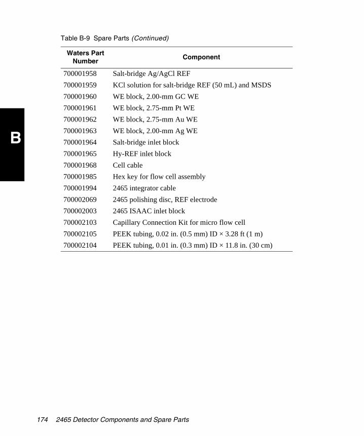
B
2465OG.book Page 174 Wednesday, November 7, 2007 10:33 AM
700001958 Salt-bridge Ag/AgCl REF
700001959 KCl solution for salt-bridge REF (50 mL) and MSDS
700001960 WE block, 2.00-mm GC WE
700001961 WE block, 2.75-mm Pt WE
700001962 WE block, 2.75-mm Au WE
700001963 WE block, 2.00-mm Ag WE
700001964 Salt-bridge inlet block
700001965 Hy-REF inlet block
700001968 Cell cable
700001985 Hex key for flow cell assembly
700001994 2465 integrator cable
700002069 2465 polishing disc, REF electrode
700002003 2465 ISAAC inlet block
700002103 Capillary Connection Kit for micro flow cell
700002105 PEEK tubing, 0.02 in. (0.5 mm) ID × 3.28 ft (1 m)
700002104 PEEK tubing, 0.01 in. (0.3 mm) ID × 11.8 in. (30 cm)
Table B-9 Spare Parts (Continued)
Waters Part Number
Component
174 2465 Detector Components and Spare Parts
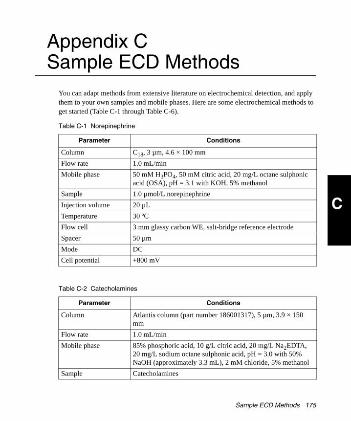
C
2465OG.book Page 175 Wednesday, November 7, 2007 10:33 AM
Appendix C Sample ECD Methods
You can adapt methods from extensive literature on electrochemical detection, and apply them to your own samples and mobile phases. Here are some electrochemical methods to get started (Table C-1 through Table C-6).
Table C-1 Norepinephrine
Parameter Conditions
Column C18, 3 µm, 4.6 × 100 mm
Flow rate 1.0 mL/min
Mobile phase 50 mM H3PO4, 50 mM citric acid, 20 mg/L octane sulphonic acid (OSA), pH = 3.1 with KOH, 5% methanol
Sample 1.0 µmol/L norepinephrine
Injection volume 20 µL
Temperature 30 ºC
Flow cell 3 mm glassy carbon WE, salt-bridge reference electrode
Spacer 50 µm
Mode DC
Cell potential +800 mV
Table C-2 Catecholamines
Parameter Conditions
Column Atlantis column (part number 186001317), 5 µm, 3.9 × 150 mm
Flow rate 1.0 mL/min
Mobile phase 85% phosphoric acid, 10 g/L citric acid, 20 mg/L Na2EDTA, 20 mg/L sodium octane sulphonic acid, pH = 3.0 with 50% NaOH (approximately 3.3 mL), 2 mM chloride, 5% methanol
Sample Catecholamines
Sample ECD Methods 175

C
2465OG.book Page 176 Wednesday, November 7, 2007 10:33 AM
Injection volume 20 µL
Temperature 35 ºC
Flow cell 2-mm glassy carbon WE, ISAAC reference electrode
Spacer 50 µm
Mode DC
Cell potential +700 mV
Table C-3 Homocysteine
Parameter Conditions
Column C18, 3 µm, 4.6 × 100 mm
Flow rate 1.0 mL/min
Mobile phase 1% phosphoric acid, 2 mM potassium chloride, 10 mg/L octane sulphonic acid, pH = 1.75 with 19.2 M NaOH
Sample 13.5 µg/L
Injection volume 20 µL
Temperature Ambient
Flow cell 3-mm gold WE, ISAAC reference electrode
Spacer 50 µm
Mode DC
Cell potential +600 mV
Table C-2 Catecholamines (Continued)
Parameter Conditions
176 Sample ECD Methods

C
2465OG.book Page 177 Wednesday, November 7, 2007 10:33 AM
Table C-4 8-Hydroxy-2-deoxyguanosine
Parameter Conditions
Column C18, 5 µm, 4.6 × 250 mm
Flow rate 1.0 mL/min
Mobile phase 50 mM citrate, pH = 3.5, 10% methanol
Sample Hydrolyzed DNA
Injection volume 50 µL
Temperature Ambient
Flow cell 3-mm glassy carbon WE, salt-bridge reference electrode
Spacer 50 µm
Mode DC
Cell potential +700 mV
Table C-5 Lactose, Sucrose, and Maltose
Parameter Conditions
Column CarboPac PA1, 4.0 × 250 mm
Flow rate 1.0 mL/min
Mobile phase 200 mM NaOH
Sample 100 nM disaccharides
Injection volume 20 µL
Temperature 30 ºC
Flow cell 3-mm gold WE, ISAAC reference electrode
Spacer 50 µm
Mode PAD (pulse)
Cell potential E1 = +150 mV, E2 = +750 mV, E3 = –800 mV
t1 = 300 ms, t2 = 150 ms, t3 = 150 ms, ts = 100 ms
Sample ECD Methods 177

C
2465OG.book Page 178 Wednesday, November 7, 2007 10:33 AM
Table C-6 Performance Qualification
Parameter Conditions
Column Symmetry C18
Flow rate 0.5 mL/min
Mobile phase 50 mM acetic acid, 50 mM sodium acetate, 5 mM potassium chloride
Sample 0.1 mg/L acetaminophen
Injection volume 20 µL
Temperature 35 ºC
Flow cell 2-mm glassy carbon WE, ISAAC reference electrode
Spacer 50 µm
Mode DC
Cell potential +650 mV
178 Sample ECD Methods
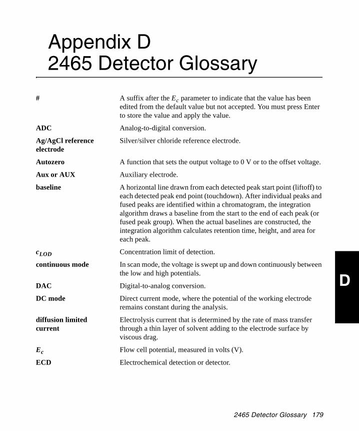
D
Appendix D 2465 Detector Glossary
2465OG.book Page 179 Wednesday, November 7, 2007 10:33 AM
# A suffix after the Ec parameter to indicate that the value has been edited from the default value but not accepted. You must press Enter to store the value and apply the value.
ADC Analog-to-digital conversion.
Ag/AgCl reference electrode
Silver/silver chloride reference electrode.
Autozero A function that sets the output voltage to 0 V or to the offset voltage.
Aux or AUX Auxiliary electrode.
baseline A horizontal line drawn from each detected peak start point (liftoff) to each detected peak end point (touchdown). After individual peaks and fused peaks are identified within a chromatogram, the integration algorithm draws a baseline from the start to the end of each peak (or fused peak group). When the actual baselines are constructed, the integration algorithm calculates retention time, height, and area for each peak.
cLOD Concentration limit of detection.
continuous mode In scan mode, the voltage is swept up and down continuously between the low and high potentials.
DAC Digital-to-analog conversion.
DC mode Direct current mode, where the potential of the working electrode remains constant during the analysis.
diffusion limited current
Electrolysis current that is determined by the rate of mass transfer through a thin layer of solvent adding to the electrode surface by viscous drag.
Ec Flow cell potential, measured in volts (V).
ECD Electrochemical detection or detector.
2465 Detector Glossary 179

D
2465OG.book Page 180 Wednesday, November 7, 2007 10:33 AM
Empower software Waters database software for Windows® XP or Windows 2000, which acquires, processes, reports, and manages chromatographic information.
Eref Potential of reference electrode.
event A programmed change of a parameter in a time file; a timed event
F Faraday’s constant, 96,500 coulombs/mole of electrons
FIA Flow injection analysis mode, where the column is deleted from the flow path (not fluorescence immunoassay).
fingertight A type of fitting (connector).
FS Full scale (units).
full scan In scan mode, a scan where the voltage is swept up and down between the low and high potentials; includes the forward and reverse scan of a compound.
GC Glassy carbon (not gas chromatography).
half scan In scan mode, a scan where the voltage is swept in one direction between the low and high potentials; either the forward or reverse scan of a compound.
hydrodynamic voltammogram
A current-potential curve for a flowing solution at constant flow rate.
Hy-REF electrode Hydrogen reference electrode.
I Current, measured in amps.
I/E Current/potential ratio.
ISAAC reference electrode
In Situ Ag/AgCl reference electrode.
KCl Potassium chloride.
LC Liquid chromatography.
LC-EC Liquid chromatography - electrochemistry.
µA Microamps.
mA Milliamps.
ms Microseconds.
nA Nanoamps.
180 2465 Detector Glossary
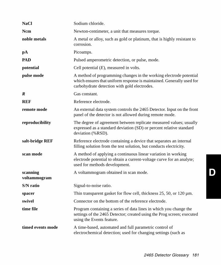
D
2465OG.book Page 181 Wednesday, November 7, 2007 10:33 AM
NaCl Sodium chloride.
Ncm Newton-centimeter, a unit that measures torque.
noble metals A metal or alloy, such as gold or platinum, that is highly resistant to corrosion.
pA Picoamps.
PAD Pulsed amperometric detection, or pulse, mode.
potential Cell potential (E), measured in volts.
pulse mode A method of programming changes in the working electrode potential which ensures that uniform response is maintained. Generally used for carbohydrate detection with gold electrodes.
R Gas constant.
REF Reference electrode.
remote mode An external data system controls the 2465 Detector. Input on the front panel of the detector is not allowed during remote mode.
reproducibility The degree of agreement between replicate measured values; usually expressed as a standard deviation (SD) or percent relative standard deviation (%RSD).
salt-bridge REF Reference electrode containing a device that separates an internal filling solution from the test solution, but conducts electricity.
scan mode A method of applying a continuous linear variation in working electrode potential to obtain a current-voltage curve for an analyte; used for methods development.
scanning voltammogram
A voltammogram obtained in scan mode.
S/N ratio Signal-to-noise ratio.
spacer Thin transparent gasket for flow cell, thickness 25, 50, or 120 µm.
swivel Connector on the bottom of the reference electrode.
time file Program containing a series of data lines in which you change the settings of the 2465 Detector; created using the Prog screen; executed using the Events feature.
timed events mode A time-based, automated and full parametric control of electrochemical detection; used for changing settings (such as
2465 Detector Glossary 181

D
2465OG.book Page 182 Wednesday, November 7, 2007 10:33 AM
sensitivity or autozero) during a run or between runs, or for control of external equipment.
voltage clamp An electronic feedback circuit that compensates for polarization effects at the electrodes.
voltammogram Graph of the measurement of a current-voltage (I/E) relationship.
WE Working electrode.
working potential Potential of the working electrode relative to that of the reference electrode.
182 2465 Detector Glossary

I NDEX
Index
2465OG.book Page 183 Wednesday, November 7, 2007 10:33 AM
Numerics2465 Bootloader program 122465 Detector
cleaning 150connections, power 39damage 39dimensions 35features 5grounding 51installing 43position in series 41principles of operation 23serial number 39setting up 87shutting down 125site requirements 36size 35spare parts 173starting up 63unpacking and inspecting 38
2695 Separations Moduleconnecting to 55generating a chart mark from 56generating an autozero on inject start 55
746 Data Moduleconnecting to 59preventing oversaturation of signal 60
AADC, defined 179Add command 67Ag/AgCl reference electrode
defined 179standard electrode potential 19
Alliance Separations Module 56Autozero
command 67control 70defined 179maximum compensation 11signal 54
AUX1 signal 54AUX2 signal 54Auxiliary electrode 14
defined 179noise 25
Azero. See Autozero
BBaseline spike 55, 69Baseline, defined 179BNC connector 8, 52, 55Brightness of screen 71Bubbles, preventing 49Buffered solvents 51, 85busSAT/IN module, connecting to 57
CCapacitance of WE 28Cell Current status 72Cell Off signal 54Cell On signal 53Cell On timed event 12Cell potential settings 71Cell volume 17Cell=On/Off command 67Changing
column clamps 44
Index 183

INDEX
2465OG.book Page 184 Wednesday, November 7, 2007 10:33 AM
columns 150spacers in flow cell 149
Chart mark 69generating from the 2695 56
Chassis ground connection 52Checksum 64Cleaning the detector 150cLOD. See Concentration limit of detectionColumn clamps 44Columns
changing 150connecting 46electrochemically clean 46equilibrating 47installing 46protecting 47RP-HPLC 47
COM portconfiguring 87settings 61
Comp (Compensation) control 71Compensation, maximum 11, 72Concentration limit of detection, defined
179Config command 68Config Output, setting 59, 60Configuration, three-electrode 15Connecting to
2695 Separations Module 55746 Data Module 59Alliance system 55busSAT/IN module 57column 46electrical power 39other systems using RS-232 60
Connecting tubing 46Connector
A 52, 53B 52, 53
BNC 8C 52DB-25 8output 52RS-232 52
Contacting Waters Technical Service 39Contrast control 71Control board 8Control parameters 66, 70Conventions, documentation xxxivCoulometry 1Creating
hydrodynamic voltammogram 120scanning voltammogram 122time files 81time files, DC mode 96time files, pulse mode 109
Current-potential curves 4Cursor keys 65Cyc (Cycle) or Cycles control 71
DDAC. See Digital-to-analog conversionDamage to the detector, inspecting 39Data acquisition
Empower 60Millennium32 software 57theory of 7
DB-25 connector 8DC command 68DC mode 23, 75
defined 179primary parameters 23programming a time file 96time files 72
Degassing, inline 42Del (Delete) command 68Detector oven 12
184 Index

INDEX
2465OG.book Page 185 Wednesday, November 7, 2007 10:33 AM
description 40temperature control 74, 89temperature derating curve 90
Developing a method 79Diag (Diagnostics) command 68Diagnostics, startup 12Diffusion limited current, defined 179Digital filter 9Digital signal communications 60Digital-to-analog conversion, defined 179Dimensions of detector 35Direct current mode 75Displ (Display) command 68Documentation
conventions xxxivrelated xxxiii
Duration of pulse 73Dynamic range, limited 15
EECD. See Electrochemical detectionElectrical connections 39Electrochemical detection 1
defined 179Electrochemical requirements for materials
15Electrodes
reference 18silver working 15working 15
Electrolysis reactions 1Electronics and data acquisition 7Empower
control 80data acquisition 60making RS-232 connections 60software 63software, defined 180
I
software, remote mode 79End cycle time 74, 84, 100Endcycle command 68Enter key 65, 67Environmental specifications 36Equilibrating the column 47Equinox card 60Error messages 152Event input
cell on/off 53reset using Events feature 53
Event output, overload 54Events command 68Events feature 53, 81
FFaraday’s law 1FIA. See Flow injection analysisFile control 72Filt (Filter) control 72Filter 72Filter time constant settings 72Filtering 9Filtering buffer 51, 85Fingertight fitting 48
defined 180Firmware version 64Flow cell
bolts 47changing spacers 149components 167descriptions 38filling 49inlet block 13installing 48kit components 38leaking 159operation 12
Index 185

INDEX
2465OG.book Page 186 Wednesday, November 7, 2007 10:33 AM
theory 14turning on 94, 107, 117
Flow cell cable 49, 50Flow cell kit 38Flow injection analysis, defined 180Flow rates, maximum 41Flowcharts
DC mode 75installing fluidics 41PAD mode 77pulse mode 77scan mode 79
Fluidic connections 41Flushing buffers before shutdown 51Front panel 64Full scan 180Function keys 65, 66, 67Fuses, replacing 148
GGenerating
autozero on inject from the 2695 55chart mark from the 2695 56
Ground connector on Connector A 54Ground connector on Connector B 54Ground stud 51
location 52Guard column 47
HHalf scan 180Heat control 12, 74Helium, degassing 47Hold/Resume commands 68HPLC
buffer 42column 42
connections 41system, passivating 45
Hydrodynamic voltammogram 4constructing 120defined 180
Hy-REF reference electrode 21, 180
II/E converter 14
function 8I/O signals 53Initializing the detector 63Inject Marker signal 55Inlet block 13Inline degasser 42Inline filter 47Input signal 55Inspecting the 2465 Detector 38Installing
detector, selecting a site 36waste tubing 46
Iodide, oxidation reaction 15Iodine analysis 15ISAAC reference electrode 18, 44, 180
KKeyb (Keyboard) command 68Keypad
front panel of 2465 64function key commands 67function keys 66
LLaboratory acquisition and control
environment. See LAC/E32
LAC/E32 57
186 Index

INDEX
2465OG.book Page 187 Wednesday, November 7, 2007 10:33 AM
Leaking flow cell 159Limiting current equation 3Line connector 52Linear flow velocity 17Locating the detector 35
MMain screen 64Maintenance, safety precautions 127Manual injector 55Mark command 69Mark signal 55MaxComp 11, 72Maximum compensation 11, 72Millennium32 software, data acquisition 57Mobile phase reservoirs 47Mobile phases 41Modes
DC 75pulse 77remote 80scan 79
NNernst equation 2Next command 69No command 69Noise 25, 27, 122
causes 45, 86Noise command 69
OOffs (Offset) control 73Operation
flow cell 12stand-alone 63
I
temperature range 36Optimizing
wave forms 26working potential 120
Other equipment, RS-232 connections 60Out of Range event 54Outp (Output) control 73Output
connector 52, 55frequency 29pulse mode 29signal 74
Oven, detector, temperature control 12, 74, 89
Overload signal 54Oversaturation of signal to 746 Data Module
60Oxidation reaction 14
PPAD mode 77, 181Parts
flow cells 167spare 129, 173Startup Kit 172
Passivationmaterials 42method 45
Polar (Polarity) command 69Polar, function 69Polarity, changing 69Potential 181
defined 181difference of electrode, equation 19optimizing 120
Potentiostat 14Power
requirements 37
Index 187

INDEX
2465OG.book Page 188 Wednesday, November 7, 2007 10:33 AM
switch 52Pressure, maximum 41, 43Prev (Previous) command 69Programming a time file
in DC mode 96in pulse mode 109
Protecting columns 47Pulse command 69Pulse mode 24, 77, 181
characteristics 25literature references 33optimizing wave forms 26output frequency 29potential settings 26primary parameters 30programming a time file 109settings 26time files 72, 109working electrode 28
Pump specifications 41
QQuit command 69
RRange 11Range control 73Rear panel, signal connections 9, 51Reduction reaction 14Reductive ECD, using detector for 47Reference electrode
available types 15Hy-REF 21ISAAC 18potential 14salt-bridge 22
Related documentation xxxiii
RELAY 1 signal 53RELAY 2 signal 53Relay output switches 53Remote mode 60, 63, 80, 181Replacing fuses 148Reproducibility 181Reset signal 53Resume command 68Reversed-phase HPLC 42
columns 47RS-232
communications port 60connections 60connector 52, 80interface 60
Run command 69
SS/N ratio 122, 181Safety and handling warnings 127Salt-bridge reference electrode 22, 181Sampling time 25
control 74SAT/IN connection 52Scan command 69Scan mode 32, 79, 122, 181
primary parameters 33using 119
Scanning voltammogram 181Screen name 67Scroll command 69Selecting a location for the detector 35Sensor board 8Serial number, instrument 39Setting detector oven temperature 89Setting up the detector 87Settings
COM port 61
188 Index
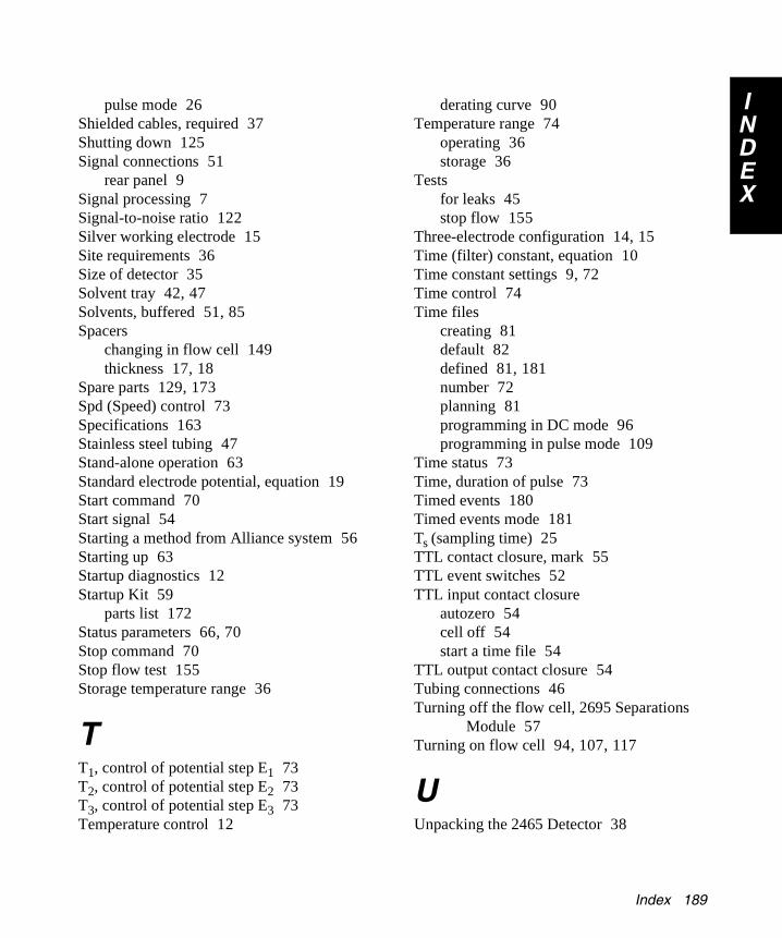
INDEX
2465OG.book Page 189 Wednesday, November 7, 2007 10:33 AM
pulse mode 26Shielded cables, required 37Shutting down 125Signal connections 51
rear panel 9Signal processing 7Signal-to-noise ratio 122Silver working electrode 15Site requirements 36Size of detector 35Solvent tray 42, 47Solvents, buffered 51, 85Spacers
changing in flow cell 149thickness 17, 18
Spare parts 129, 173Spd (Speed) control 73Specifications 163Stainless steel tubing 47Stand-alone operation 63Standard electrode potential, equation 19Start command 70Start signal 54Starting a method from Alliance system 56Starting up 63Startup diagnostics 12Startup Kit 59
parts list 172Status parameters 66, 70Stop command 70Stop flow test 155Storage temperature range 36
TT1, control of potential step E1 73T2, control of potential step E2 73T3, control of potential step E3 73Temperature control 12
I
derating curve 90Temperature range 74
operating 36storage 36
Testsfor leaks 45stop flow 155
Three-electrode configuration 14, 15Time (filter) constant, equation 10Time constant settings 9, 72Time control 74Time files
creating 81default 82defined 81, 181number 72planning 81programming in DC mode 96programming in pulse mode 109
Time status 73Time, duration of pulse 73Timed events 180Timed events mode 181Ts (sampling time) 25TTL contact closure, mark 55TTL event switches 52TTL input contact closure
autozero 54cell off 54start a time file 54
TTL output contact closure 54Tubing connections 46Turning off the flow cell, 2695 Separations
Module 57Turning on flow cell 94, 107, 117
UUnpacking the 2465 Detector 38
Index 189

INDEX
2465OG.book Page 190 Wednesday, November 7, 2007 10:33 AM
VValue keys 65Valve control 74Ventilation 40Verifying COM port settings 61Voltage clamp 182Voltage output 74Voltammogram 182
constructing 120creating hydrodynamic 120creating scanning 122defined 182
Voltammogram, hydrodynamic 4Vout, status 74
WWaste tubing, installing 46Waters Technical Service, contacting 39Working electrode 14
capacitance 28diameter 16material 28size 16
Working potential 15, 182defined 182limits 16optimizing 120
YYes command 70
190 Index


![ç ‚ EBG -W˝‚ · 2011-06-08 · 3 ßyjgzc zc#Ö} ¯ÝgzZDäs¯yZZü äÛn¿´äÛnÛŁŠ’+flZgY#aÚŽ ŠÜ ß × ł › ł æ ł ä ô n ß × ł ´ ł o F Ö^ˆ ł ł i ö†]o](https://static.fdocuments.fr/doc/165x107/5f74168c4c5c664bb05a8064/-a-ebg-wa-2011-06-08-3-yjgzc-zc-gzzdsyzz-nnaizgya.jpg)