2080-WD012A-EN-P Micro800 High Speed Counter Plug...
16
Wiring Diagrams Micro800 High Speed Counter Plug-in Module Catalog Numbers 2080-MOT-HSC http://www.rockwellautomation.com/literature/ FR Cette publication est disponible en français sous forme électronique (fichier PDF). Pour la télécharger, rendez-vous sur la page Internet indiquée ci-dessus. IT Questa pubblicazione è disponibile in Italiano in formato PDF. Per scaricarla collegarsi al sito Web indicato sopra. DE Diese Publikation ist als PDF auf Deutsch verfügbar. Gehen Sie auf die oben genannte Web-Adresse, um nach der Publikation zu suchen und sie herunterzuladen. ES Esta publicación está disponible en español como PDF. Diríjase a la dirección web indicada arriba para buscar y descarga esta publicación. PT Esta publicação está disponível em portugués como PDF. Vá ao endereço web que aparece acima para encontrar e fazer download da publicação. ZH ZC KO IMPORTANT To properly configure the HSC plug-in using Connected Components Workbench software, refer to the Connected Components Workbench Online Help that comes with your software installation.
Transcript of 2080-WD012A-EN-P Micro800 High Speed Counter Plug...
Wiring Diagrams
Micro800 High Speed Counter Plug-in Module
Catalog Numbers 2080-MOT-HSC
http://www.rockwellautomation.com/literature/
FR Cette publication est disponible en français sous forme électronique (fichier PDF). Pour la télécharger, rendez-vous sur la page Internet indiquée ci-dessus.
IT Questa pubblicazione è disponibile in Italiano in formato PDF. Per scaricarla collegarsi al sito Web indicato sopra.
DEDiese Publikation ist als PDF auf Deutsch verfügbar. Gehen Sie auf die oben genannte Web-Adresse, um nach der Publikation zu suchen und sie herunterzuladen.
ES Esta publicación está disponible en español como PDF. Diríjase a la dirección web indicada arriba para buscar y descarga esta publicación.
PT Esta publicação está disponível em portugués como PDF. Vá ao endereço web que aparece acima para encontrar e fazer download da publicação.
ZH
ZC
KO
IMPORTANT To properly configure the HSC plug-in using Connected Components Workbench software, refer to the Connected Components Workbench Online Help that comes with your software installation.

2 Micro800 High Speed Counter Plug-in Module
Environment and Enclosure
Preventing Electrostatic Discharge
ATTENTION: This equipment is intended for use in a Pollution Degree 2 industrial environment, in overvoltage Category II applications (as defined in IEC 60664-1), at altitudes up to 2000 m (6562 ft) without derating.This equipment is not intended for use in residential environments and may not provide adequate protection to radio communication services in such environments.This equipment is supplied as open-type equipment. It must be mounted within an enclosure that is suitably designed for those specific environmental conditions that will be present and appropriately designed to prevent personal injury resulting from accessibility to live parts. The enclosure must have suitable flame-retardant properties to prevent or minimize the spread of flame, complying with a flame spread rating of 5VA or be approved for the application if nonmetallic. The interior of the enclosure must be accessible only by the use of a tool. Subsequent sections of this publication may contain additional information regarding specific enclosure type ratings that are required to comply with certain product safety certifications.In addition to this publication, see the following:
• Industrial Automation Wiring and Grounding Guidelines, Rockwell Automation publication 1770-4.1, for additional installation requirements.
• NEMA Standard 250 and IEC 60529, as applicable, for explanations of the degrees of protection provided by different types of enclosure.
ATTENTION: This equipment is sensitive to electrostatic discharge, which can cause internal damage and affect normal operation. Follow these guidelines when you handle this equipment:
• Touch a grounded object to discharge potential static.• Wear an approved grounding wriststrap.• Do not touch connectors or pins on component boards.• Do not touch circuit components inside the equipment.• Use a static-safe workstation, if available.• Store the equipment in appropriate static-safe packaging when not in
use.
Rockwell Automation Publication 2080-WD012A-EN-P - December 2013

Micro800 High Speed Counter Plug-in Module 3
North American Hazardous Location ApprovalThe following module is North American Hazardous Location approved: 2080-MOT-HSC
The following information applies when operating this equipment in hazardous locations:
Informations sur l’utilisation de cet équipement en environnements dangereux:
Products marked "CL I, DIV 2, GP A, B, C, D" are suitable for use in Class I Division 2 Groups A, B, C, D, Hazardous Locations and nonhazardous locations only. Each product is supplied with markings on the rating nameplate indicating the hazardous location temperature code. When combining products within a system, the most adverse temperature code (lowest "T" number) may be used to help determine the overall temperature code of the system. Combinations of equipment in your system are subject to investigation by the local Authority Having Jurisdiction at the time of installation.
Les produits marqués "CL I, DIV 2, GP A, B, C, D" ne conviennent qu'à une utilisation en environnements de Classe I Division 2 Groupes A, B, C, D dangereux et non dangereux. Chaque produit est livré avec des marquages sur sa plaque d'identification qui indiquent le code de température pour les environnements dangereux. Lorsque plusieurs produits sont combinés dans un système, le code de température le plus défavorable (code de température le plus faible) peut être utilisé pour déterminer le code de température global du système. Les combinaisons d'équipements dans le système sont sujettes à inspection par les autorités locales qualifiées au moment de l'installation.
WARNING: EXPLOSION HAZARD• Do not disconnect equipment
unless power has been removed or the area is known to be nonhazardous.
• Do not disconnect connections to this equipment unless power has been removed or the area is known to be nonhazardous. Secure any external connections that mate to this equipment by using screws, sliding latches, threaded connectors, or other means provided with this product.
• Substitution of any component may impair suitability for Class I, Division 2.
• If this product contains batteries, they must only be changed in an area known to be nonhazardous.
AVERTISSEMENT: RISQUE D’EXPLOSION• Couper le courant ou s'assurer que
l'environnement est classé non dangereux avant de débrancher l'équipement.
• Couper le courant ou s'assurer que l'environnement est classé non dangereux avant de débrancher les connecteurs. Fixer tous les connecteurs externes reliés à cet équipement à l'aide de vis, loquets coulissants, connecteurs filetés ou autres moyens fournis avec ce produit.
• La substitution de tout composant peut rendre cet équipement inadapté à une utilisation en environnement de Classe I, Division 2.
• S'assurer que l'environnement est classé non dangereux avant de changer les piles.
Rockwell Automation Publication 2080-WD012A-EN-P - December 2013

4 Micro800 High Speed Counter Plug-in Module
Parts List
Your package contains one Micro800™ High Speed Counter (HSC) plug-in module, two module fastening screws, and these pinout guide wiring instructions.
WARNING: If you insert or remove the plugin module while power is on, an electrical arc can occur. This could cause an explosion in hazardous location installations.Be sure that power is removed or the area is nonhazardous before proceeding.
WARNING: When used in a Class I, Division 2, hazardous location, this equipment must be mounted in a suitable enclosure with proper wiring method that complies with the governing electrical codes.
ATTENTION: This plug-in module is intended for use with Micro800 family of programmable controllers.
46217
Channel Status LEDindicators
Rockwell Automation Publication 2080-WD012A-EN-P - December 2013

Micro800 High Speed Counter Plug-in Module 5
You can choose to wire the plug-in before inserting it onto the controller, or wire it once the module is secured in place.
Insert Module into Controller Follow the instructions to insert and secure the plug-in module to the controller.
WARNING: If you insert or remove the module while the controller power is on, an electrical arc can occur. This could cause an explosion in hazardous location installations. Be sure that power is removed or the area is nonhazardous before proceeding.
WARNING: When used in a Class I, Division 2, hazardous location, this equipment must be mounted in a suitable enclosure with proper wiring method that complies with the governing electrical codes.
46216
Rockwell Automation Publication 2080-WD012A-EN-P - December 2013

6 Micro800 High Speed Counter Plug-in Module
1. Position the plug-in module with the terminal block facing the front of the controller as shown.
2. Snap the module into the module bay.
3. Using a screwdriver, tighten the 10…12 mm (0.39…0.47 in.) M3 self tapping screw to torque specifications.
Wire the ModuleThe module includes a single 8-pin terminal block. Follow the pinout diagram when wiring your module.
WARNING: If you connect or disconnect wiring while the field-side power is on, an electrical arc can occur. This could cause an explosion in hazardous location installations. Be sure that power is removed or the area is nonhazardous before proceeding.
1 2 3 4
1 2 3 4
Back
Front
B
A
(View into terminal block)Pin A1 0- Pin B1 0+Pin A2 A- Pin B2 A+Pin A3 B- Pin B3 B+Pin A4 Z- Pin B4 Z+
CR
0-
A-
B-
Z-
A+
B+
Z+
0+ DC(+)
DC(-)
0-
A-
B-
Z-
A+
B+
Z+
0+ DC(+)
DC(-)
CR
Sinking Output Wiring Sourcing Output Wiring
Rockwell Automation Publication 2080-WD012A-EN-P - December 2013

Micro800 High Speed Counter Plug-in Module 7
Wiring Examples for 2080-MOT-HSCThe plug-in module supports differential inputs in which two input terminals are required for each input point, for example, A+ and A-. The plug-in module also supports single-ended devices such as limit switches, photo-eyes, and proximity sensors. See the following examples.
VS
GND
+V DC
COM
A(+)
A(-)
B(+)
B(-)
Z(+)
Z(-)
Earth
A_A
B_B
Z_Z
Shield/HousingConnect only if housing is electronically isolated from the motor and ground.
Differential encoder wiring
Cable
Shield
Powersupply
Module inputs
Allen-Bradley845H SeriesDifferentialEncoder
Rockwell Automation Publication 2080-WD012A-EN-P - December 2013

8 Micro800 High Speed Counter Plug-in Module
VS
GND
+V DC
COM
A(+)
A(-)
B(+)
B(-)
Z(+)
Z(-)
Earth
A
B
Z
Shield/HousingConnect only if housing is electronically isolated from the motor and ground.
Single-ended encoder wiring
Powersupply
Module inputs
Cable
Shield
Allen-Bradley845H SeriesDifferentialEncoder
VS
OUT
VS
OUT
COM
+V DC
COM
A(+)
A(-)
B(+)
B(+)
COM
VS
OUT
COM
Z(+)
Z(-)
R
Discrete device wiring
Photo-electric sensor with open collector sinking output
Solid state switch
Module Inputs
Powersupply
Rockwell Automation Publication 2080-WD012A-EN-P - December 2013

Micro800 High Speed Counter Plug-in Module 9
Specifications
General Specifications
Attribute Value
Dimensions, HxWxD, approx 62 x 31.5 x 20 mm (2.44 x 1.24 x 0.79 in.)
Terminal screw torque 0.22…0.25 Nm (1.95…2.21 lb-in.)using a 2.5 mm (0.10 in.) flat-blade screwdriver
Bus current draw 60 mA @ 3.3V DC
Recommended cable Individually shielded, twisted-pair cable (or the type recommended by the encoder or sensor manufacturer)
Wire size
Enclosure type rating Meets IP20
Isolation voltage Input module: 50V (continuous), Basic Insulation Type, Inputs/Outputs to BackplaneType tested for 60s @ 720V DC, Inputs/Outputs to Backplane
Wiring Category(1)
(1) Use this Conductor Category information for planning conductor routing. Refer to Industrial Automation Wiring and Grounding Guidelines, publication 1770-4.1.
2 – on signal ports
North American Temp Code T4
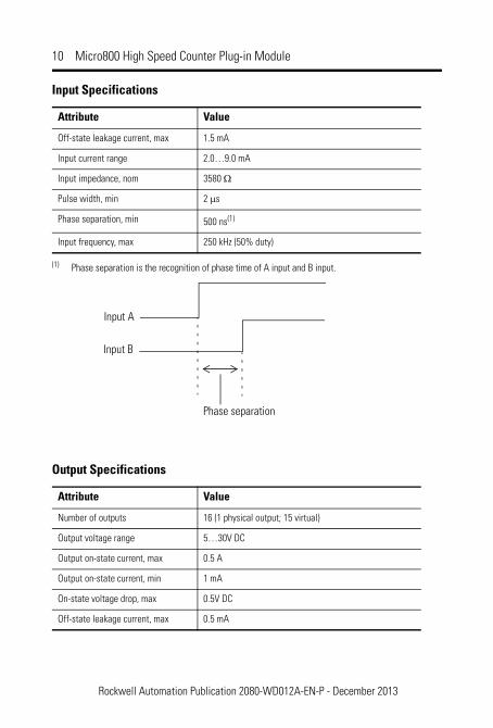
Input Specifications
Attribute Value
Number of inputs 1 Quadrature (ABZ) differential input
Input voltage range 0…30V DC
On state voltage range 2.6…30V DC
On-state current, min 2.0 mA
Off-state voltage, max 1.0V DC
Min Max
Solid 0.14 mm2 (26 AWG) 1.5 mm2 (16 AWG) rated @ 90 °C (194 °F) insulation maxStranded 0.14 mm2 (26 AWG) 1.0 mm2 (18 AWG)
Rockwell Automation Publication 2080-WD012A-EN-P - December 2013
10 Micro800 High Speed Counter Plug-in Module
Off-state leakage current, max 1.5 mA
Input current range 2.0…9.0 mA
Input impedance, nom 3580 Ω
Pulse width, min 2 μs
Phase separation, min 500 ns(1)
Input frequency, max 250 kHz (50% duty)
(1) Phase separation is the recognition of phase time of A input and B input.
Output Specifications
Attribute Value
Number of outputs 16 (1 physical output; 15 virtual)
Output voltage range 5…30V DC
Output on-state current, max 0.5 A
Output on-state current, min 1 mA
On-state voltage drop, max 0.5V DC
Off-state leakage current, max 0.5 mA
Input Specifications
Attribute Value
Input A
Input B
Phase separation
Rockwell Automation Publication 2080-WD012A-EN-P - December 2013

Micro800 High Speed Counter Plug-in Module 11
Temperature Derating
Maximum Input Voltage – 24V DC Operation
Turn ON time, max 2 ms
Turn OFF time, max 2 ms
Reverse polarity protection None
Output Specifications
Attribute Value
-20 -10 0 10 20 30 40 50 60 70
0
5
10
15
20
25
30
35
Volts
(DC)
Ambient Temperature (°C)
Voltage Derating Based on Temperature
26.4V DC @ 65 °C
Rockwell Automation Publication 2080-WD012A-EN-P - December 2013

12 Micro800 High Speed Counter Plug-in Module
Maximum Output Voltage – 24V DC Operation
Maximum Output Current per Point – 5V DC Operation
-20 -10 0 10 20 30 40 50 60 70
0
5
10
15
20
25
30
35
Volts
(DC)
Ambient Temperature (°C)
Voltage Derating Based on Temperature
26.4V DC @ 65 °C
-20 -10 0 10 20 30 40 50 60 70
0
0.5
1
1.5
Curre
nt p
er p
oint
s (A
)
Ambient Temperature (°C)
Current Derating Based on Temperature
Rockwell Automation Publication 2080-WD012A-EN-P - December 2013

Micro800 High Speed Counter Plug-in Module 13
Maximum Output Current per Point – 24V DC Operation
-20 -10 0 10 20 30 40 50 60 70
0
0.5
1
1.5
Curre
nt p
er p
oint
s (A
)
Ambient Temperature (°C)
Current Derating Based on Temperature
Rockwell Automation Publication 2080-WD012A-EN-P - December 2013

14 Micro800 High Speed Counter Plug-in Module
Environmental Specifications
Attribute Value
Temperature, operating IEC 60068-2-1 (Test Ad, Operating Cold),IEC 60068-2-2 (Test Bd, Operating Dry Heat),IEC 60068-2-14 (Test Nb, Operating Thermal Shock):-20…65 °C (-4…149 °F)
Temperature, nonoperating IEC 60068-2-1 (Test Ab, Unpackaged Nonoperating Cold),IEC 60068-2-2 (Test Bb, Unpackaged Nonoperating Dry Heat),IEC 60068-2-14 (Test Na, Unpackaged Nonoperating Thermal Shock):-40…85 °C (-40…185 °F)
Temperature, surrounding air, max 65 °C (149 °F)
Relative humidity IEC 60068-2-30 (Test Db, Unpackaged Damp Heat):5…95% noncondensing
Vibration IEC 60068-2-6 (Test Fc, Operating):2 g @ 10…500 Hz
Shock, operating IEC 60068-2-27 (Test Ea, Unpackaged Shock):25 g
Shock, nonoperating IEC 60068-2-27 (Test Ea, Unpackaged Shock):25 g35 g (PANEL mount)
Emissions CISPR 11 (IEC 61000-6-4):Class A
ESD immunity IEC 61000-4-2:6 kV contact discharges8 kV air discharges
Radiated RF immunity IEC 61000-4-3:10V/m with 1 kHz sine-wave 80% AM from 80…2000 MHz10V/m with 200 Hz 50% Pulse 100% AM @ 900 MHz10V/m with 200 Hz 50% Pulse 100% AM @ 1890 MHz10V/m with 1 kHz sine-wave 80% AM from 2000…2700 MHz
EFT/B immunity IEC 61000-4-4:±2 kV @ 5 kHz on signal ports
Surge transient immunity IEC 61000-4-5:±2 kV line-earth(CM) on shielded ports
Conducted RF immunity IEC 61000-4-6:10V rms with 1 kHz sine-wave 80% AM from 150 kHz…80 MHz
Rockwell Automation Publication 2080-WD012A-EN-P - December 2013

Micro800 High Speed Counter Plug-in Module 15
Additional ResourcesThese documents contain additional information concerning related Rockwell Automation products.
If you need more information on these products, contact your local Rockwell Automation distributor or sales office. The documentation listed in the Related Documentation table is available at http://www.rockwellautomation.com/literature.
Certifications
Certification (when product is marked)(1)
Value
c-UL-us UL Listed Industrial Control Equipment, certified for US and Canada. See UL File E322657.
UL Listed for Class I, Division 2 Group A,B,C,D Hazardous Locations, certified for U.S. and Canada. See UL File E334470.
CE EN 61326-1; Meas./Control/Lab., Industrial RequirementsEN 61000-6-2; Industrial ImmunityEN 61000-6-4; Industrial EmissionsEN 61131-2; Programmable Controllers (Clause 8, Zone A & B)
RCM Australian Radiocommunications Act, compliant with:AS/NZS CISPR 11; Industrial Emissions
KC Korean Registration of Broadcasting and Communications Equipment, compliant with:Article 58-2 of Radio Waves Act, Clause 3
(1) See the Product Certification link at http://www.rockwellautomation.com/products/certification/ for Declarations of Conformity, Certificates, and other certification details.
Resource Description
Micro800 Plug-in Modules, publication 2080-UM004
Information on installing, wiring, and descriptions of the different digital and analog Micro800 plug-in modules.
Industrial Automation Wiring and GroundingGuidelines, publication 1770-4.1
Provides general guidelines for installing a Rockwell Automation industrial system.
Product Certifications website, http://www.rockwellautomation.com/products/certification/
Provides declarations of conformity, certificates, and other certification details.
Rockwell Automation Publication 2080-WD012A-EN-P - December 2013

Rockwell Automation SupportRockwell Automation provides technical information on the Web to assist you in using its products. At http://www.rockwellautomation.com/support/, you can find technical manuals, a knowledge base of FAQs, technical and application notes, sample code and links to software service packs, and a MySupport feature that you can customize to make the best use of these tools.
For an additional level of technical phone support for installation, configuration and troubleshooting, we offer TechConnect support programs. For more information, contact your local distributor or Rockwell Automation representative, or visit http://www.rockwellautomation.com/support/.
Installation AssistanceIf you experience a problem within the first 24 hours of installation, please review the information that's contained in this manual. You can also contact a special Customer Support number for initial help in getting your product up and running.
New Product Satisfaction ReturnRockwell Automation tests all of its products to ensure that they are fully operational when shipped from the manufacturing facility. However, if your product is not functioning and needs to be returned, follow these procedures.
Documentation FeedbackYour comments will help us serve your documentation needs better. If you have any suggestions on how to improve this document, complete this form, publication RA-DU002, available at http://www.rockwellautomation.com/literature/.
United States or Canada 1.440.646.3434
Outside United States or Canada
Use the Worldwide Locator at http://www.rockwellautomation.com/support/americas/phone_en.html, or contact your local Rockwell Automation representative.
United States Contact your distributor. You must provide a Customer Support case number (call the phone number above to obtain one) to your distributor to complete the return process.
Outside United States Please contact your local Rockwell Automation representative for the return procedure.
Publication 2080-WD012A-EN-P - December 2013 PN-212613
Allen-Bradley, Rockwell Automation, and Micro800, are trademarks of Rockwell Automation, Inc.
Trademarks not belonging to Rockwell Automation are property of their respective companies.
Copyright © 2013 Rockwell Automation, Inc. All rights reserved. Printed in Malaysia.