2-Port Flow Control Valve with Digital Electronics 2-Wege ...
32
IM14156.R4 Installation manual Installationshandbuch Manuel d’installation FLOWTRONIC D 2-Port Flow Control Valve with Digital Electronics 2-Wege-Durchflussregelventil mit Digitaler Technik Vanne de régulation de débit à 2 orifices Electronique numérique Series / Baureihe / Série 607 GB DE FR
Transcript of 2-Port Flow Control Valve with Digital Electronics 2-Wege ...

IM14156.R4
Installation manualInstallationshandbuchManuel d’installation
FLOWTRONICD
2-Port Flow Control Valve with Digital Electronics2-Wege-Durchfl ussregelventil mit Digitaler Technik
Vanne de régulation de débit à 2 orificesElectronique numérique
Series / Baureihe / Série 607
GB
Installation manualInstallationshandbuchManuel d’installation
DE FR

IM14156-2
INSTALLATIONGB
SUMMARY - INHALT - SOMMAIRE
English version _____________________________________________________________________2
1. Description .......................................................................................................................................3
1.1 Codes ......................................................................................................................................3 1.2 Operating elements .................................................................................................................3 1.3 Manual setpoint adjustment ...................................................................................................4 1.4 Operating modes ....................................................................................................................4
2. Electrical connection .........................................................................................................................5
3. Pneumatic connection .......................................................................................................................6
4. Factory settings .................................................................................................................................6
5. Field-programmable settings .............................................................................................................6
6. Technical characteristics ...................................................................................................................7
6.1 Fluid characteristics ................................................................................................................7 6.2 Electrical characteristics .........................................................................................................7
7. Accessories .......................................................................................................................................8
8. Maintenance and care .......................................................................................................................8
9. Dimensions and weight .....................................................................................................................8
Deutsche Version __________________________________________________________________11
Version française __________________________________________________________________21
CAUTION! Dangerous operating conditions may occur when using the programming interface on the valve as the valve may possibly not react to the analog setpoint any more.Provide for protection against uncontrolled movement of equipment when putting the valve into operation and before making any modifications to the valve settings.
NOTICEThe information in this manual is subject to change without notice.In no event shall ASCO NUMATICS be liable for technical or editorial errors or omissions. Neither is any liability assumed for accidental or consequential damages arising out of or in connection with the supply or use of the information contained herein.THIS MANUAL CONTAINS INFORMATION PROTECTED BY COPYRIGHT. NO PART OF THIS DOCUMENT MAY BE PHOTOCOPIED OR REPRODUCED IN ANY FORM OR MANNER WHATSOEVER WITHOUT PRIOR WRITTEN PERMISSION FROM ASCO NUMATICS.
COPYRIGHT © 2016 - ASCO NUMATICS - All rights reserved.
E S D
This product complies with the essential requirements of the EMC Directive 2014/30/EU and its amendments. It is CE-approved. A separate Declaration of Conformity is available on request.Please provide ordering code and serial numbers of products concerned.
We herewith declare that the version of the product described in this installation manual is intended to be incorporated into or assembled with other machinery and that it must not be put into service until the machinery into which it is to be incorporated has been declared in conformity with the provisions of Council Directive 2006/42/EC.Handling, assembly and putting into service and all settings and adjustments must be done by qualified, authorised personnel only.
This product contains electronic components sensitive to electrostatic discharge. An electrostatic discharge generated by a person or object coming in contact with the electrical components can damage or destroy the product.To avoid the risk of electrostatic discharge, please observe the handling precautions and recommendations contained in standard EN 100015-1. Do not connect or disconnect the device while it is energised.
C A U T I O NOBSERVE PRECAUTIONS
FOR HANDLINGELECTROSTATIC SENSITIVE
DEVICES
!
GB
FR
DE

IM14156-3
INSTALLATION GB
1 Proportional solenoid cover2 Power supply, M12 connector3 USB port, M12B connector4 Operator buttons5 3-digit display of flow6.1 Green LED OFF: Setpoint ≠ feedback ON: Setpoint = feedback Flashing: Overtemperature6.2 Yellow LED OFF: Normal ON: Manual operation Flashing: AUTOSAFE enabled6.3 Red LED OFF: Normal ON: Low voltage Flashing: Overvoltage
1.2 OPERATING ELEMENTS
3
2
6.3
5
4
1
6.1 6.2
1. DESCRIPTIONThe FLOwTRONICD flow controller is especially designed for applications placing extreme dynamic demands on flow control. It consists of a fast, direct-acting 2-port proportional valve and a control unit that contains all the electronics and sensors. The FLOwTRONICD offers precise flow adjustment and responds to outside influences within no time at all. Highest accuracy is achieved by measuring the flow with two sensors. The FLOwTRONICD directly regulates the actual rate of flow and adjusts it quickly to changing conditions. The use of digital control electronics and a USB interface allow the FLOwTRONICD to be adapted to different applications. An auto-tune function and the ASCO FlowCom PC software provide easy start-up. Diagnosis of the FLOwTRONICD is made possible over the integrated LEDs and the ASCO FlowCom PC software ASCO FlowCom. The FLOwTRONICD is available with or without LED display and operating buttons.
1.1 CODES
pipesize DN
flow (1) max. inlet pressure
catalogue number
with display without display
setpoint / output feedback setpoint / output feedback
G (l/min) (bar) 0 - 10 V 0 - 20 mA 4 - 20 mA 0 - 10 V 0 - 20 mA 4 - 20 mA
1/4
2 5 - 50 8 60701073 60701081 60701089 60701074 60701082 60701090
310 - 100 8 60701055 60701063 60701071 60701056 60701064 6070107212 - 300 8 60701019 60701027 60701035 60701020 60701028 60701036
5 20 - 500 8 60701001 60701009 60701017 60701002 60701010 607010183/8 6 50 - 1000 8 60701037 60701045 60701053 60701038 60701046 607010541/2 8 100 - 2000 8 60701091 60701099 60701107 60701092 60701100 60701108
(1) Measurement without flow restriction at the outlet / with regard to standard conditions (T=0°C; P=1013 mbar)

IM14156-4
INSTALLATIONGB
1.3 MANUAL SETPOINT ADJUSTMENT (HAND)
After an interruption in the power supply, press both arrow buttons located beneath the display during power up to switch to the manual mode. The operating mode is indicated by the letters “H n d” in the display.
The "H n d" display disappears when the arrow buttons are released. Press the left arrow button or DOWN arrow to reduce the flow, press the right arrow button or UP arrow to increase
the flow. The yellow LED is on permanently during manual mode. Exit this operating mode by pressing both arrow buttons simultaneously or by turning off the power supply for a
short time.
1.4 OPERATING MODES
Shut-off: If the setpoint falls below 0.5 %, the control valve is switched off and the flow is interrupted.
Overtemperature: If the temperature of the internal control electronics exceeds 100°C the green LED starts to flash.
Undervoltage / overvoltage: If the supply voltage is less than 19 V or more than 30 V, the control valve is switched off and the valve is locked.
The red LED lights up constantly to indicate undervoltage or flashes to indicate overvoltage.

IM14156-5
INSTALLATION GB
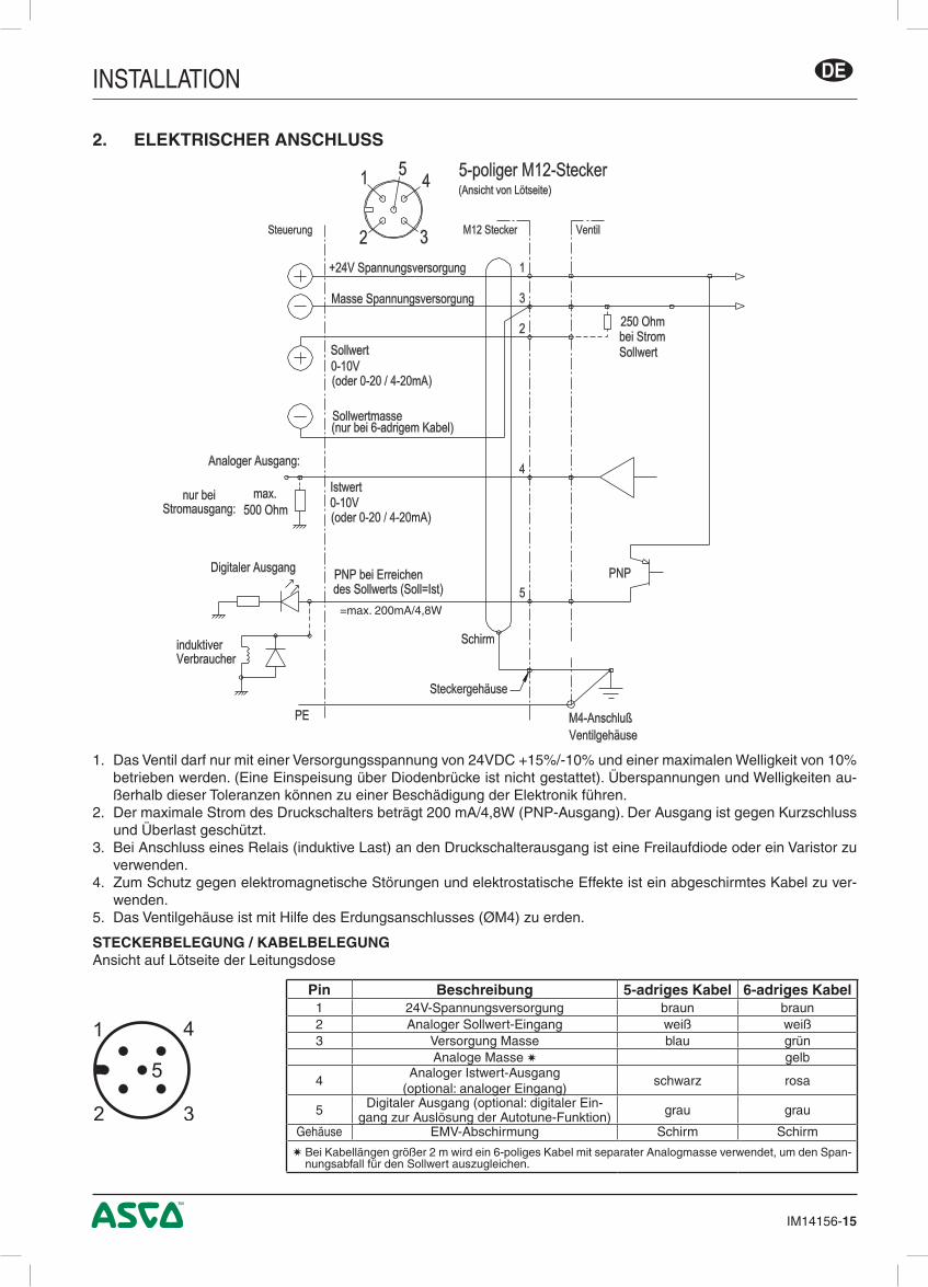
1) The valve must only be supplied with 24V DC at a tolerance of +15%/-10% and a max. ripple of 10% (no supply via diode bridge). Overvoltage or a ripple rate exceeding these tolerances can damage the electronics.
2) The max. current at the digital output is 200 mA/4.8W (PNP output). The output is protected against short circuit and overload.
3) If a relay (inductive load) is connected to the digital output, a freewheel diode or a varistor must be used.4) A shielded cable must be used for protection against interference and EMC.5) The valve body must be grounded with the earthing terminal PE (dia. M4)
2. ELECTRICAL CONNECTION
CONNECTOR PINNING / CABLE WIRINGView on soldered side of female connector
Pin Description 5-wire cable 6-wire cable1 24V voltage supply brown brown2 Analog setpoint input white white3 Supply ground blue green
Analog ground yellow
4Analog output (feedback) (optional: analog input)
black pink
5 Digital output (optional: digital input to acti-vate the autotune function) grey grey
Body EMC shield shield shield A 6-wire cable with separate analog ground is used for cable lengths over 2 m to set off the voltage drop for
the setpoint.
5-pin M12 female connector(view on soldered side)
250 Ohm at current setpoint
ValveM12 connector
+24V supply voltage
Supply voltage GND
Setpoint GND(only for 6-wire cable)
Setpoint0-10V(or 0-20 / 4-20mA)
Feedback0-10V(or 0-20 / 4-20mA)
Control
Analog output:
Only at current output: max. 500 ohm
Digital output:PNP when setpoint is reached (setpoint=feedback)
Inductive load
M4 connection on valve body
Connector housing
Shield
=200mA max./4.8W
1
2 3
5
4
IM14156-6
INSTALLATIONGB
4. FACTORY SETTINGS
- Setpoint offset: 0 l/min flow rate at a setpoint of 0 Volt or 0/4 mA. - Span: max. flow value l/min at a setpoint of 10 V / 20 mA. - Minimum hysteresis. - The control parameters, setpoint offset, setpoint span and window size of the digital output are factory-pro-
grammed.
Parameter set: factory settingsSetpoint offset: 0 %Setpoint span: 100 %Setpoint ramp: no rampShut-off: ON; the flow rate is 0 at a setpoint below 0.5%Controller structure: PIDProportional gain: 0,1Integration time: 0.2 secDerivation time: 0 msecWindow size: 5 %
5. FIELD-PROGRAMMABLE SETTINGS
DISPLAYThe actual flow rate is displayed in l/min during normal operation. In case of version 2000 l/min the flow rate is shown in m³/h.
Hnd indicates that the Manual mode has been selected.
PUSHBUTTONSTo enter the Manual mode, press and hold both pushbuttons simultaneously and power off and power up again."Hnd" appears in the display.Use the UP button to increase the flow rate and the DOWN button to decrease it. The actual flow rate is displayed.Quick presses on the buttons allow you to make slight changes in the flow rate. Longer presses allow you to make larger changes in the flow rate.Press both pushbuttons simultaneously to exit the "Manual mode" and return to the "Regular mode". Pressing the UP or DOWN button in "Regular mode" causes the display to blink and show the setpoint in %. Press the UP or DOWN button again to display the actual flow rate.
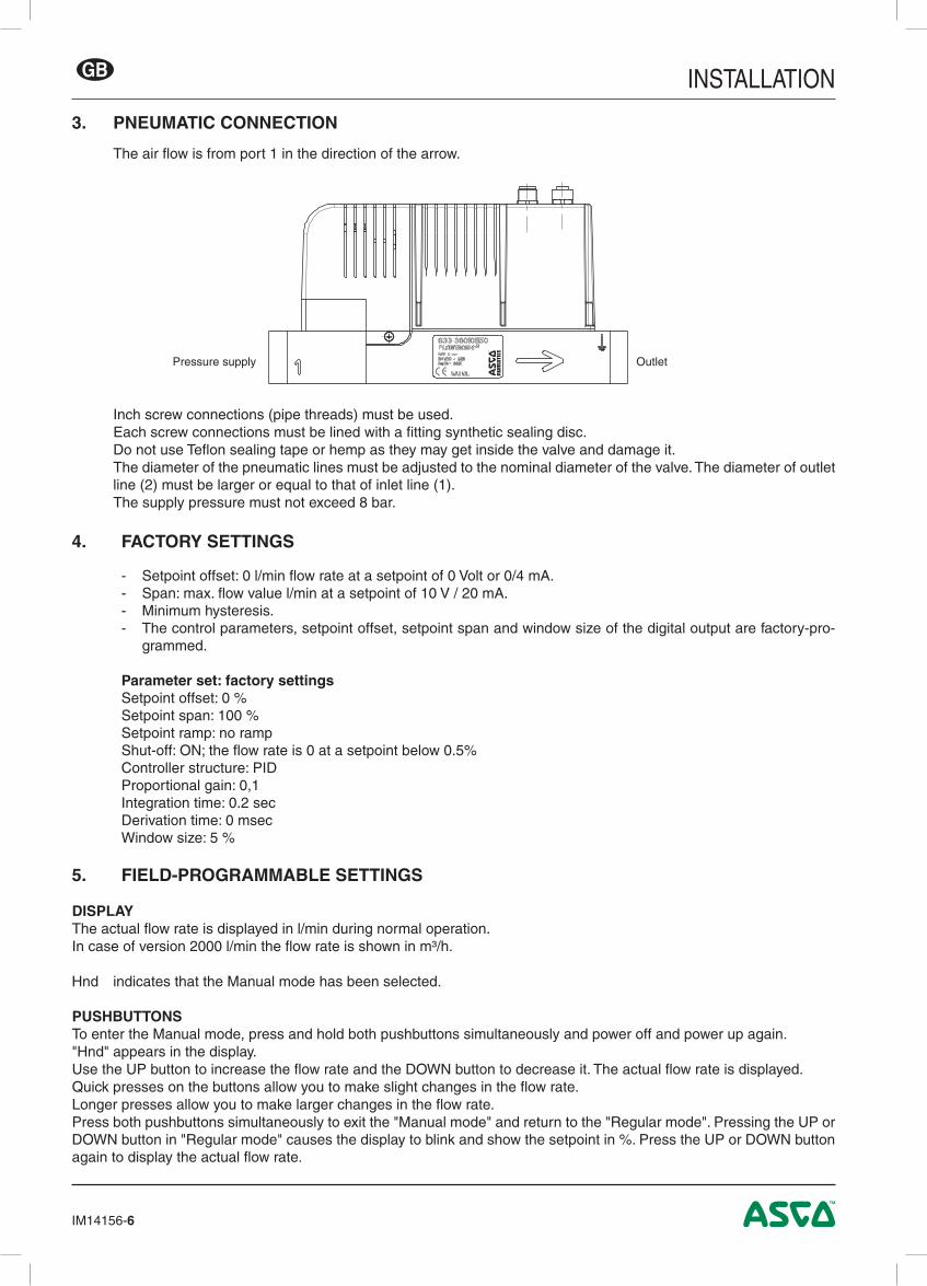
3. PNEUMATIC CONNECTION
The air flow is from port 1 in the direction of the arrow.
Inch screw connections (pipe threads) must be used.Each screw connections must be lined with a fitting synthetic sealing disc.Do not use Teflon sealing tape or hemp as they may get inside the valve and damage it.The diameter of the pneumatic lines must be adjusted to the nominal diameter of the valve. The diameter of outlet line (2) must be larger or equal to that of inlet line (1). The supply pressure must not exceed 8 bar.
OutletPressure supply

IM14156-7
INSTALLATION GB
5. FIELD-PROGRAMMABLE SETTINGS (cont'd)
AUTOTUNEAUTOTUNE determines the forward current the proportional valve needs to open. This control parameter, called forward offset, is permanently stored.
AUTOTUNE can be activated in the three following ways:1. Press and hold the AUTOTUNE button, switch the supply voltage off and on again, and release the AUTOTUNE but-
ton.2. Over the ASCO-FlowCom operating software.3. If the appropriate option has been selected over the operating software, AUTOTUNE can be activated over the digital
input (M12, Pin 5).
After having determined the forward offset, the device will automatically go into Regular mode.
6. TECHNICAL CHARACTERISTICS
CONSTRUCTION INSTALLATIONDirect operated poppet valveBody: AluminiumInternal parts: Aluminium, brass, stainless steelSeals: NBR
Assembly position: any (solenoid upright preferred)
6.1 Fluid characteristics
FLUID : Air or nitrogen (N2), filtered at 50 µm, without condensate, lubricated or notMAX. AIR PRESSURE (MAP) : 8 barBAND OF REGULATION (PMR) : 5 - 2000 l/min (up to max. 6 bar outlet pressure), consult us for other ranges)TEMPERATURE FLUID : 0° C to +50° C AMBIENT : 0° C to +40° CSETPOINT - ANALOG : 0 - 10 V (100 kΩ), 0/4 to 20 mA (resistance 250 Ω)FEEDBACK - ANALOG : 0 - 10 V, 0/4 to 20 mA (max. load 500 Ω)FLOW ACCURACY HYSTERESIS : ± 3% LINEARITY : ± 3% REPEATABILITY : ± 1,5%CALIBRATION CONDITIONS AMBIENT TEMPERATURE : 22,5°C ±2,5°C FLUID : AirDYNAMIC PERFORMANCE RESPONSE TIME : < 200 msOTHER FEATURES : Auto-tune, error display by 3 LEDs
6.2 Electrical characteristics
nominal diameter DN
voltage *max. power
(W)
max. current
(mA)insulation class
degree of protec-tion
electrical connection
2, 3, 5 and 624 V = +/-10%
30 1250H IP65
- 5 pin M12 connector - USB connection with 4 pin
M12 connector8 44 1800
* Max. ripple: 10 %

IM14156-8
INSTALLATIONGB
7. ACCESSORIES
Description CODESFLOwTRONICD software "ASCO-FlowCom-Light" - CD-ROM 881 00 895FLOwTRONICD software "ASCO-FlowCom-Expert" - CD-ROM 881 00 896G 1/2" adapter 881 60 701G 3/8" adapter 881 60 702USB cable for connection of FLOwTRONICD to PC 881 00 897Straight M12 female connector, 5 pins, with screw terminals 881 00 256Right-angle M12 female connector, 5 pins, with screw terminals 881 00 725Supply cable 2 m, 5x0,25 mm², straight connector 881 00 726Supply cable 2 m, 5x0,25 mm², right-angle connector 881 00 727Supply cable 5 m, 6x0,56 mm², straight connector 881 00 728Supply cable 5 m, 6x0,56 mm², right-angle connector 881 00 729Supply cable 10 m, 6x0,56 mm², straight connector 881 00 730Supply cable 10 m, 6x0,56 mm², right-angle connector 881 00 731
8. MAINTENANCE AND CARE
No special maintenance or care required.
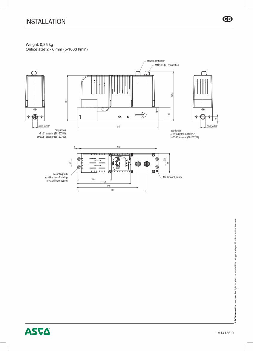
9. DIMENSIONS AND WEIGHT
Weight: 1,2 kg Orifice size 8mm (100-2000 l/min)
267 ± 0,5%
5045
15
136
138,
8
1420
,534,5
70
81
150,
1
G1/2" G1/2"
201224
2,35
IM14156-9
INSTALLATION GB
AS
CO
Nu
mat
ics
rese
rves
the
right
to a
lter
the
avai
labi
lity,
des
ign
and
spec
ifica
tions
with
out n
otic
e.
* (optional) G1/2" adapter (88160701)
or G3/8" adapter (88160702)
M12x1 USB connection
M4 for earth screw
M12x1 connector
Mounting with4xM4 screws from top or 4xM5 from bottom
* (optional) G1/2" adapter (88160701) or G3/8" adapter (88160702)
Weight: 0,85 kgOrifice size 2 - 6 mm (5-1000 l/min)

IM14156-10
INSTALLATIONGB
ASCO Numatics GmbH Otto-Hahn-Straße 7-11 75248 Ölbronn-Dürrn Germany
Tel: +49 7237 996-0 Email: [email protected] www.asconumatics.eu

IM14156-DE.R4
Installationshandbuch
2-Wege-Durchfl ussregelventilmit Digitaler Technik
Baureihe 607FLOWTRONICD
DE

IM14156-12
INSTALLATIONDE
INHALT1. Beschreibung ............................................................................................................................................ 13
1.1 Geräteauswahl ................................................................................................................................. 13
1.2 Bedienelemente ............................................................................................................................... 13
1.3 Manuelle Sollwert-Verstellung .......................................................................................................... 14
1.4 Betriebszustände ............................................................................................................................. 14
2. Elektrischer Anschluss ............................................................................................................................... 15
3. Pneumatischer Anschluss .......................................................................................................................... 16
4. Angaben zur werkseitigen Einstellung ....................................................................................................... 16
5. Einstellmöglichkeiten .................................................................................................................................. 16
6. Technische Daten ....................................................................................................................................... 17
6.1 Fluidtechnische Daten ..................................................................................................................... 17
6.2 Elektrische Daten ............................................................................................................................. 17
7. Zubehör ...................................................................................................................................................... 18
8. Wartung und Pflege ................................................................................................................................... 18
9. Abmessungen und Gewichte ..................................................................................................................... 18
ANMERKUNGENDIE IN DIESEM HANDBUCH ENTHALTENEN ANGABEN KÖNNEN OHNE VORHERIGE ANKÜNDIGUNG GEÄNDERT WERDEN.ASCO NUMATICS übernimmt keinerlei Haftung für technische oder redaktionelle Fehler oder Ungenauigkeiten oder für versehentlich entstehende Schäden oder Folgeschäden, die durch die Bereitstellung dieses Handbuchs oder aus der Anwendung desselben entstehen.DAS VORLIEGENDE HANDBUCH ENTHÄLT URHEBERRECHTLICH GESCHÜTZTE ANGABEN. KEIN TEIL DIESES HANDBUCHS DARF OHNE VORHERIGE SCHRIFTLICHE GENEHMIGUNG VON ASCO NUMATICS AUF IRGENDEINE ART UND WEISE VERVIELFÄLTIGT ODER ÜBERTRA-GEN WERDEN.
COPYRIGHT © 2016 - ASCO NUMATICS - Alle Rechte vorbehalten.
Dieses Produkt enthält elektronische Bauteile, die gegenüber elektrostati-schen Entladungen (ESD) empfindlich sind. Berührungen der elektrischen Bauteile durch Personen oder Gegenstände können zu einer elektrostati-schen Entladung führen, die das Produkt beschädigt oder zerstört.Um das Risiko einer elektrostatischen Entladung zu vermieden, sind die Handhabungshinweise und Empfehlungen nach EN 100015-1 zu beachten.Zum elektrischen Anschließen oder Trennen des Produkts ist die Versor-gungsspannung abzuschalten.E S D
A C H T U N GVORSICHT BEI HANDHABUNG
VON ELEKTROSTATISCH GEFÄHRDETEN
BAUTEILEN (EGB)
Dieses Produkt entspricht der Richtlinie 2014/30/EU und deren Ergänzungen über die Elektromagnetische Verträglichkeit. Es ist nach CE zugelassen. Eine Konformitätserklärung steht auf Anfrage zur Verfügung.
Geben Sie bitte für die entsprechenden Produkte die Artikelnummer und Seriennummer an.
Hiermit erklären wir, dass das in diesem Installationshandbuch beschriebene Gerät in der von uns gelieferten Ausführung zum Einbau oder Zusam-menbau mit anderen Maschinen bestimmt ist, und dass die Inbetriebnahme so lange untersagt ist, bis festgelegt wurde, dass die Maschine in die das Gerät eingebaut werden soll, den Bestimmungen der Richtlinie 2006/42/EG entspricht.Die Handhabung, Montage und Inbetriebnahme, sowie Einstell- und Justierarbeiten dürfen ausschließlich von autorisiertem Fachpersonal durchgeführt werden.
ACHTUNG! Wenn die Programmierschnittstelle am Ventil benutzt wird, können gefährliche Betriebszustände auftreten, da das Ventil möglicherweise nicht mehr auf den angelegten analogen Sollwert reagiert.Bei Inbetriebnahme und vor Änderungen der Ventileinstellungen sind Vorkehrungen gegen unkontrollierte Bewegung von Anlagenteilen zu treffen.
!

IM14156-13
INSTALLATION DE
1. BESCHREIBUNGDer Durchflussregler FLOwTRONICD wurde speziell für Anwendungen entwickelt, die höchste dynamische Anforde-rungen an die Durchflussregelung stellen. Es besteht aus einem hochdynamischen, direktbetätigten 2-Wege-Pro-portionalventil und einer Regeleinheit, die die gesamte Regelelektronik und Sensorik beinhaltet. Das FLOwTRONICD regelt exakt den Durchfluss und reagiert auf Störgrößen von außen innerhalb kürzester Zeit. Die hohe Genauigkeit wird durch die interne Erfassung des Durchflusses mit Hilfe von zwei Sensoren erreicht. Mit dem FLOwTRONICD wird der tatsächliche Volumendurchfluss direkt geregelt und schnell an die veränderten Bedingungen angepasst.
Durch den Einsatz einer vollständig digitalen Regelelektronik und einer USB-Schnittstelle kann FLOwTRONICD an die unterschiedlichsten Applikationen angepasst werden. Über Autotune und eine zusätzlichen PC-Software ASCO FlowCom (AFC) erfolgt die komfortable Inbetriebnahme. Eine Diagnose des FLOwTRONICD ist ebenfalls über die eingebauten LEDs oder über die PC-Software ASCO FlowCom möglich. FLOwTRONICD ist mit und ohne LED-Anzeige und Bedientasten lieferbar.
1.1 GERÄTEAUSWAHL
ØAnschluss
ØDN
(mm)
Durchfluss-regelbereich 1)
Max. Eingangsdruck
(bar)
Artikel-Nr.
mit Display ohne Display
Sollwertvorgabe / Istwert-Ausgang Sollwertvorgabe / Istwert-Ausgang
G (l/min) (bar) 0 - 10 V 0 - 20 mA 4 - 20 mA 0 - 10 V 0 - 20 mA 4 - 20 mA
1/4
2 5 - 50 8 60701073 60701081 60701089 60701074 60701082 60701090
310 - 100 8 60701055 60701063 60701071 60701056 60701064 6070107212 - 300 8 60701019 60701027 60701035 60701020 60701028 60701036
5 20 - 500 8 60701001 60701009 60701017 60701002 60701010 607010183/8 6 50 - 1000 8 60701037 60701045 60701053 60701038 60701046 607010541/2 8 100 - 2000 8 60701091 60701099 60701107 60701092 60701100 60701108
1) Messung ohne Drosselstelle am Ausgang / bezogen auf Normbedingungen (T=0°C; P=1013 mbar)
1.2 BEDIENELEMENTE
1 Abdeckung Proportionalmagnet2 Elektrische Versorgung, M12-Stecker3 USB-Anschluss, M12B-Dose4 Bedientasten5 3-stellige Anzeige für den Durchfluss6.1 Grüne LED AUS: Soll ≠ Ist EIN: Soll = Ist Blinkend: Übertemperatur6.2 Gelbe LED AUS: Normal EIN: Handbetrieb Blinkend: AUTOSAFE eingeschaltet6.3 Rote LED AUS: Normal EIN: Unterspannung Blinkend: Überspannung
3
2
6.3
5
4
1
6.1 6.2

IM14156-14
INSTALLATIONDE
1.3 MANUELLE SOLLWERT-VERSTELLUNG (HANDBETRIEB)
Wird die Versorgungsspannung unterbrochen, wird nach einem erneuten Zuschalten der Versorgungsspannung und bei gleichzeitigen Drücken der beiden Pfeiltasten unterhalb des Displays in den Betriebszustand „Handbetrieb“ gewechselt. Dieser Betriebszustand wird im Display durch die Zeichen "H n d" angezeigt.
Die Anzeige "H n d" verschwindet nach Loslassen der Pfeiltasten. Mittels der Pfeiltasten kann der Durchfluss (linke Pfeiltaste bzw. Pfeilrichtung nach unten => Reduzierung des
Durchflusses, rechte Pfeiltaste bzw. Pfeilrichtung nach oben => Erhöhung des Durchflusses) verändert werden. Während des Handbetriebs leuchtet die gelbe LED dauernd. Dieser Betriebszustand kann durch das gleichzeitige
Drücken beider Pfeiltasten oder durch das kurzzeitige Abtrennen der Versorgungsspannung verlassen werden.
1.4 BETRIEBSZUSTÄNDE
Shutoff: Wird der Sollwert kleiner 0,5 %, so wird das Regelventil stromlos geschaltet und der Durchfluss ist unterbrochen.
Übertemperatur: Erreicht die interne Regelelektronik eine Temperatur größer 100 °C, blinkt die grüne LED.
Unter-/Überspannung: Wird die Versorgungsspannung kleiner 19 V oder größer 30 V, so wird das Regelventil abgeschaltet und das Ventil
sperrt. Die rote LED leuchtet (Unterspannung) oder blinkt (Überspannung).
IM14156-15
INSTALLATION DE
1. Das Ventil darf nur mit einer Versorgungsspannung von 24VDC +15%/-10% und einer maximalen Welligkeit von 10% betrieben werden. (Eine Einspeisung über Diodenbrücke ist nicht gestattet). Überspannungen und Welligkeiten au-ßerhalb dieser Toleranzen können zu einer Beschädigung der Elektronik führen.
2. Der maximale Strom des Druckschalters beträgt 200 mA/4,8W (PNP-Ausgang). Der Ausgang ist gegen Kurzschluss und Überlast geschützt.
3. Bei Anschluss eines Relais (induktive Last) an den Druckschalterausgang ist eine Freilaufdiode oder ein Varistor zu verwenden.
4. Zum Schutz gegen elektromagnetische Störungen und elektrostatische Effekte ist ein abgeschirmtes Kabel zu ver-wenden.
5. Das Ventilgehäuse ist mit Hilfe des Erdungsanschlusses (ØM4) zu erden.
2. ELEKTRISCHER ANSCHLUSS
STECKERBELEGUNG / KABELBELEGUNGAnsicht auf Lötseite der Leitungsdose
=max. 200mA/4,8W
Pin Beschreibung 5-adriges Kabel 6-adriges Kabel1 24V-Spannungsversorgung braun braun2 Analoger Sollwert-Eingang weiß weiß3 Versorgung Masse blau grün
Analoge Masse gelb
4Analoger Istwert-Ausgang
(optional: analoger Eingang)schwarz rosa
5 Digitaler Ausgang (optional: digitaler Ein-gang zur Auslösung der Autotune-Funktion) grau grau
Gehäuse EMV-Abschirmung Schirm Schirm
Bei Kabellängen größer 2 m wird ein 6-poliges Kabel mit separater Analogmasse verwendet, um den Span-nungsabfall für den Sollwert auszugleichen.
1
2 3
5
4
IM14156-16
INSTALLATIONDE
4. ANGABEN ZUR WERKSEINSTELLUNG
- Nullpunkt: Durchfluss 0 l/min bei einem Sollwert von 0 Volt bzw. 0/4 mA. - Spanne: max.Durchflusswert l/min bei einem Sollwert von 10 V / 20 mA. - Minimale Hysterese. - Die Regelparameter, der Nullpunkt, die Spanne und die Fensterbreite (5 %) des Digitalausganges sind werk-
seitig programmiert.
Parametersatz: WerkNullpunkt: 0 %Spanne: 100 %Sollwertrampe: keineShutoff: EIN; bei Sollwert kleiner 0,5 % ist der Durchfluss 0Reglerstruktur: PIDProportionalverstärkung: 0,1Integrationszeit: 0,2 secDifferentialzeit: 0 msecFensterbreite: 5 %
5. EINSTELLMÖGLICHKEITEN
DISPLAYIm Normalbetrieb wird hier der aktuelle Durchfluss in l/min angezeigt. Bei der 2000 l/min-Version wird der Durchfluss in m³/h angezeigt.
Hnd Zeigt, dass der Handbetrieb aufgerufen wurde.
DRUCKTASTENUm den Handbetrieb aufzurufen, beide Tasten gedrückt halten und die Versorgungsspannung aus- und wieder einschalten.Im Display erscheint die Anzeige "Hnd".Die Taste "AUF" benutzen, um den Durchfluss zu erhöhen, und die Taste "AB", um den Durchfluss zu erniedrigen. Im Display wird der aktuelle Durchfluss angezeigt.Kurzes Betätigen der Tasten ergibt kleine Durchflussänderungen.Langes Betätigen der Tasten führt zu großen Durchflussänderungen.Beide Tasten gleichzeitig drücken um den "Handbetrieb" zu verlassen und in den "Normalbetrieb" zu gelangen. Durch Betätigen der Taste "AUF" oder "AB" im "Normalbetrieb" beginnt die Anzeige zu blinken und zeigt den angelegten Sollwert in % an. Durch erneutes Betätigen der Taste "AUF" oder "AB" wird wieder der aktuelle Durchfluss angezeigt.
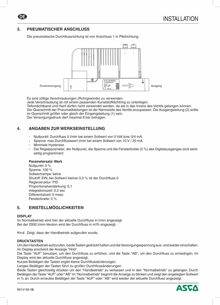
3. PNEUMATISCHER ANSCHLUSS
Die pneumatische Durchflussrichtung ist von Anschluss 1 in Pfeilrichtung.
Es sind zöllige Verschraubungen (Rohrgewinde) zu verwenden.Jede Verschraubung ist mit einem passenden Kunststoffdichtring zu unterlegen.Teflondichtband und Hanf dürfen nicht verwendet werden, da sie in das Innere des Ventils gelangen können.Der Querschnitt der Pneumatikleitungen ist der Nennweite des Ventils anzupassen. Die Ausgangsleitung (2) sollte im Querschnitt größer oder gleich der Eingangsleitung (1) sein. Der Versorgungsdruck darf maximal 8 bar betragen.
AusgangDruckversorgung

IM14156-17
INSTALLATION DE
5. EINSTELLMÖGLICHKEITEN (Fortsetzung)
AUTOTUNEAUTOTUNE ermittelt den Ansteuerstrom, den das Proportionalventil benötigt, um zu öffnen. Dieser als Vorsteuernullpunkt bezeichnete Regelparameter wird permanent abgespeichert.
Um AUTOTUNE zu starten, gibt es drei Möglichkeiten:1. Die Taste AUTOTUNE gedrückt halten, die Versorgungsspannung aus- und wieder einschalten und die Taste anschlie-
ßend loslassen.2. Über die Bediensoftware ASCO-FlowCom.3. Falls über die Bediensoftware die entsprechende Option ausgewählt wurde, kann AUTOTUNE über den digitalen
Eingang (M12, Pin 5) gestartet werden.
Nach der Ermittlung des Vorsteuernullpunkts geht das Gerät automatisch in den Normalbetrieb.
6. TECHNISCHE DATEN
KONSTRUKTIONSMERKMALE MONTAGEDirektgesteuertes VentilGehäuse: AluminiumInnenteile: Aluminium, Messing, EdelstahlDichtungsmaterialien: NBR
Einbaulage: beliebig, Magnet vorzugsweise nach oben
6.1 Fluidtechnische Daten
MEDIUM : Luft oder Stickstoff (N2), Filterung 50 µm, ohne Kondensat, geölt oder ungeöltBETRIEBSDRUCK MAX. : 8 barREGELBEREICH : 5 - 2000 l/min (bis max. 6 bar Ausgangsdruck), andere Regelbereiche auf An-
frageTEMPERATUR MEDIUM : 0 °C bis 50 °C UMGEBUNG : 0 °C bis 40 °CSOLLWERT - ANALOG : 0 - 10 Volt (100 kΩ), 0/4 bis 20 mA (Bürde 250 Ω)ISTWERT - ANALOG : 0 - 10 Volt, 0/4 bis 20 mA (max. Bürde 500 Ω)GENAUIGKEIT HYSTERESE : ± 3 % LINEARITÄT : ± 3 % WIEDERHOLGENAUIGKEIT : ± 1,5 %KALIBRIERUNGSBEDINGUNGEN UMGEBUNGSTEMPERATUR : 22,5 °C ±2,5 °C MEDIUM : LuftDYNAMISCHES VERHALTEN SCHALTZEIT : < 200 msSONSTIGES : Autotune, Status über 3 LEDs
6.2 Elektrische Daten
NennweiteDN
(mm)Spannung *
Leistungsaufnahme max. (W)
Stromaufnahme max.(mA)
Isolations- klasse
Schutzart Kabelanschluss
2, 3, 5 und 624 V = +/-10%
30 1250H IP65
- 5-polige M12-Leitungsdose - USB-Anschluss über 4-polige
M12-Leitungsdose8 44 1800
* Restwelligkeit: 10 %

IM14156-18
INSTALLATIONDE
7. ZUBEHÖR
Beschreibung Bestell-CodeFLOwTRONICD-Software "ASCO-FlowCom-Light" auf CD-ROM 881 00 895
FLOwTRONICD-Software "ASCO-FlowCom-Expert" auf CD-ROM 881 00 896
G 1/2"-Adapter 881 60 701
G 3/8"-Adapter 881 60 702
USB-Verbindungskabel zwischen FLOwTRONICD und PC 881 00 897
Gerade M12 Leitungsdose, 5-polig, mit Schraubklemmen 881 00 256
M12 Winkel-Leitungsdose, 5-polig, mit Schraubklemmen 881 00 725
Spannungsversorgungskabel 2 m, 5x0,25 mm², gerade Leitungsdose 881 00 726
Spannungsversorgungskabel 2 m, 5x0,25 mm², Winkel-Leitungsdose 881 00 727
Spannungsversorgungskabel 5 m, 6x0,56 mm², gerade Leitungsdose 881 00 728
Spannungsversorgungskabel 5 m, 6x0,56 mm², Winkel-Leitungsdose 881 00 729
Spannungsversorgungskabel 10 m, 6x0,56 mm², gerade Leitungsdose 881 00 730
Spannungsversorgungskabel 10 m, 6x0,56 mm², Winkel-Leitungsdose 881 00 731
8. WARTUNG UND PFLEGE
Keine besonderen Anforderungen.
9. ABMESSUNGEN UND GEWICHTE
Gewicht 1,2 kg Nennweite 8mm (100-2000 l/min)
267 ± 0,5%
5045
15
136
138,
8
1420
,534,5
70
81
150,
1
G1/2" G1/2"
201224
2,35

IM14156-19
INSTALLATION DE
Gewicht: 0,85 kgNennweite 2 - 6 mm (5-1000 l/min)
Än
der
un
gen
vo
rbeh
alte
n.
* (optional) G1/2"-Adapter (88160701)
oder G3/8"-Adapter (88160702)
* (optional) G1/2"-Adapter (88160701) oder G3/8"-Adapter (88160702)

IM14156-20
INSTALLATIONDE
ASCO Numatics GmbH Otto-Hahn-Straße 7-11 75248 Ölbronn-Dürrn Germany
Tel: +49 7237 996-0 Email: [email protected] www.asconumatics.eu

IM14156-FR.R4
Manuel d'installation
Vanne de régulation de débit à 2 orifi cesElectronique numérique
SÉRIE 607FLOWTRONICD
FR

IM14156-22
INSTALLATIONFR
SOMMAIRE1. Description ................................................................................................................................................. 23
1.1 Sélection du matériel ....................................................................................................................... 23
1.2 Composants de fonctionnement ...................................................................................................... 23
1.3 Réglage manuel du débit (mode Manuel) ........................................................................................ 24
1.4 Modes de fonctionnement ................................................................................................................ 24
2. Raccordement électrique ........................................................................................................................... 25
3. Raccordement pneumatique ...................................................................................................................... 26
4. Réglages usine .......................................................................................................................................... 26
5. Réglages programmables sur site .............................................................................................................. 26
6. Caractéristiques techniques ....................................................................................................................... 27
6.1 Caractéristiques du fluide ................................................................................................................ 27
6.2 Caractéristiques électriques ............................................................................................................. 27
7. Accessoires ................................................................................................................................................ 28
8. Maintenance et entretien ............................................................................................................................ 28
9. Encombrements et masse ......................................................................................................................... 28
ATTENTION! Des conditions d’exploitation dangereuses peuvent se développer en utilisant l’interface de programmation sur la vanneétant donné que la vanne ne réagira éventuellement plus à la consigne analogique appliquée.Assurer une protection contre des mouvements incontrôlés de l’équipement lors de la mise en service de la vanne et avant d’effectuer des modifications sur les réglages de la vanne.
E S D
!
Ce produit contient des composants électroniques sensibles aux décharges électrostatiques. Tout contact des connexions par une personne ou un objet chargé d’électricité statique pourrait entraîner la mise en panne ou la destruction de l’appareil.Pour réduire les risques de décharges électrostatiques, veuillez respecter les recommandations et précautions de manipulation définies par la norme EN100 015-1, avant toute intervention sur ce produit.Ne jamais brancher ou débrancher l’appareil lorsqu’il est sous tension.
NOTESLes informations contenues dans le présent manuel sont susceptibles d’être modifiées sans préavis.ASCO NUMATICS ne peut être tenu responsable des omissions techniques ou rédactionnelles, ni des dommages accidentels ou consécutifs à la fourniture ou l’utilisation du présent document.LE PRESENT MANUEL CONTIENT DES INFORMATIONS PROTEGEES PAR COPYRIGHT, AUCUNE PARTIE DU PRESENT DOCUMENT NE PEUT ETRE PHOTOCOPIEE OU REPRODUITE SOUS QUELQUE FORME QUE CE SOIT SANS AUTORISATION ECRITE PREALABLE DE ASCO NUMATICS.
COPYRIGHT © 2016 - ASCO NUMATICS - Tous droits réservés.
Ce produit est conforme aux exigences essentielles de la Directive 2014/30/UE sur la Compatibilité Electromagnétique, et amendements. Une déclaration de conformité peut être fournie sur simple demande.
Veuillez nous indiquer les références ou codes des produits concernés.
Par la présente nous déclarons que le produit décrit dans ce manuel d’installation, est destiné pour être installé dans une machine ou à être assemblé à une autre machine: Toutefois il est interdit de mettre le produit en fonctionnement tant que la machine dans laquelle il est déstiné à être incorporé ou l’ensemble de machines solidaires auquel il doit être assemblé n’aura pas été déclaré conforme aux dispositions de la Directive Machines 2006/42/CE.Toutes opérations de manutention, d’installation et de mise en service, ainsi que la mise au point et le réglage doivent être effectués uniquement par un personnel qualifié et autorisé.
ATTENTIONRESPECTER LES PRECAUTIONS
DE MANIPULATION DES PRODUITS SENSIBLES
AUX DECHARGESELECTROSTATIQUES

IM14156-23
INSTALLATION FR
1. DESCRIPTION
Le régulateur de débit FLOwTRONICD est parfaitement adapté pour les régulations de débit extrêmement dynamiques. Il est composé d’une vanne proportionnelle à 2 voies à commande directe pour un temps de réponse court, d'un bloc capteurs de pression et d'une électronique numérique de régulation. Le FLOwTRONICD régule et maintient le débit constant quelles que soient les perturbations externes. Le débit est mesuré à l'aide de 2 capteurs, ce qui permet une très haute précision.Le FLOwTRONICD peut être adapté à diverses applications grâce à l'électronique numérique configurable par PC via l'interface USB. La fonction auto-tune et le logiciel ASCO FlowCom permettent une mise en service simple et rapide. Le diagnostic du FLOwTRONICD se fait au moyen des LEDs intégrées au produit ou via logiciel ASCO FlowCom. Le FLOwTRONICD est disponible avec ou sans affichage LED et boutons en façade.
1.1 SELECTION DU MATERIEL
SELECTION DU MATERIEL
Ø raccordement DN
débit (1) pression d'entrée maxi
code
avec affichage sans affichage
point de consigne / retour sortie point de consigne / retour sortie
G (l/min) (bar) 0 - 10 V 0 - 20 mA 4 - 20 mA 0 - 10 V 0 - 20 mA 4 - 20 mA
1/4
2 5 - 50 8 60701073 60701081 60701089 60701074 60701082 60701090
310 - 100 8 60701055 60701063 60701071 60701056 60701064 6070107212 - 300 8 60701019 60701027 60701035 60701020 60701028 60701036
5 20 - 500 8 60701001 60701009 60701017 60701002 60701010 607010183/8 6 50 - 1000 8 60701037 60701045 60701053 60701038 60701046 607010541/2 8 100 - 2000 8 60701091 60701099 60701107 60701092 60701100 60701108
(1) Mesure sans restriction de débit à la sortie / Dans les conditions Normales (T=0°C; P=1013 mbar)
1.2 COMPOSANTS DE FONCTIONNEMENT
1 Protection de la bobine proportionnelle2 Alimentation, connecteur mâle M12
codage A3 Raccordement USB, connecteur femelle
M12 codage B4 Touches de commande5 Affichage du débit à 3 chiffres6.1 LED verte ETEINTE: Consigne ≠ retour ALLUMEE: Consigne = retour Clignotante: Surchauffe6.2 LED jaune ETEINTE: Fonctionnement normal ALLUMEE: Fonctionnement manuel Clignotante: AUTOSAFE activée6.3 LED rouge ETEINTE: Fonctionnement normal ALLUMEE: Sous-tension Clignotante: Surtension
3
2
6.3
5
4
1
6.1 6.2

IM14156-24
INSTALLATIONFR
1.3 REGLAGE MANUEL DE LA CONSIGNE (MODE MANUEL)
Pour passer en mode Manuel après une coupure de l’alimentation électrique, appuyer sur les deux boutons-pous-soirs à flèche qui se trouvent sous l’affichage pendant la remise sous tension. Le mode de fonctionnement est indiqué par l'affichage des lettres « Hnd ».L'affichage "Hnd" disparaît après avoir relâché les boutons-poussoirs.Appuyer sur le bouton-poussoir de gauche ou flèche vers le BAS pour diminuer le débit, appuyer sur le bou-ton-poussoir de droite ou flèche vers le HAUT pour augmenter le débit. Le voyant jaune est constamment allumé pendant le mode Manuel.Quitter ce mode de fonctionnement en appuyant simultanément sur les deux boutons-poussoirs à flèche ou en coupant l’alimentation pendant un temps > 5 sec.
1.4 MODES DE FONCTIONNEMENT
Shut off (fermeture) :Si la valeur de consigne devient inférieure à 0,5% de la PMR, le courant de la vanne de régulation est coupé et le débit est interrompu.Surchauffe :Si la température du système électronique de contrôle interne dépasse 100°C, le voyant vert se met à clignoter.Sous-tension / surtension :Si la tension d’alimentation est inférieure à 19 V ou supérieure à 30 V, la bobine est mise hors tension et la vanne est fermée (pas de débit).Le voyant rouge reste - constamment allumé pour indiquer une sous-tension-clignote pour indiquer une surtension.

IM14156-25
INSTALLATION FR
2. RACCORDEMENT ELECTRIQUE
RACCORDEMENT CONNECTEUR / RACCORDEMENT DE CABLERépérage vu côté soudure du connecteur femelle
Broche Description Câble 5 fils (2m) Câble 6 fils (5m, 10m)
1 Alimentation en tension 24V marron marron
2 Entrée de la consigne analogique blanc blanc
3 Masse d'alimentation bleu vert
Masse analogique jaune
4 Sortie analogique (valeur de retour) noir rose
5 Sortie numérique (pressostat) gris gris
Enveloppe Blindage CEM blindage blindage) Un câble de 6 fils avec masse analogique séparée est utilisé pour les longueurs de câble de plus
de 2 m afin de compenser la chute de tension pour la consigne.
Connecteur femelle M12 5 broches (vue du côté soudure)
250 Ohm à la consigne courante
VanneConnecteur M12
Alimentation +24V
Masse d’alimentation GND
Masse consigne(seulement pour câbleà 6 fils)
Consigne 0-10V(ou 0-20 / 4-20mA)
Retour0-10V(ou 0-20 / 4-20mA)
Contrôle
Sortie analogique:
Seulement pour sortie courant max. 500 ohm
Sortie numérique:PNP si consigne atteinte(consigne = retour)
Charge inductive
Connexion M4 sur corps de la vanne
Boîtier du connecteur
Blindage
= 200mA max./4,8 W
1) La vanne doit être alimentée en 24V, courant continu, variation +10%/-10%, avec un taux d'ondulation maxi. de 10% (pas d'alimentation par pont de diode). Une surtension ou un taux d'ondulation en dehors de ces tolérances peuvent détériorer l'électronique.
2) Le courant maxi. sur le pressostat est de 200 mA/4,8W (sortie PNP). La sortie est protégée contre les court-circuits et les surcharges.
3) Si vous connectez un relais (charge inductive) sur la sortie pressostat, il est nécessaire d'utiliser une diode de roue libre ou une varistance.
4) Utiliser un câble blindé contre les parasites et les effets électrostatiques. 5) Le corps de la vanne doit être relié à la terre par l'intermédiaire de la borne de masse PE (ØM4).
1
2 3
5
4

IM14156-26
INSTALLATIONFR
4. REGLAGES USINE
- Réglage du zéro : Débit de 0 l/min pour une consigne de 0 V / 0 mA / 4 mA. - Réglage de la pente : Valeur de débit maximum en l/min pour une consigne de 10 V / 20 mA. - Hystérésis minimal. - Les paramètres de contrôle, l’écart de la consigne, la pente de consigne et la taille de la fenêtre (5 %) de la
sortie numérique sont programmés en usine.
Paramètres de réglage : réglage usineRéglage du zéro : 0 %Réglage de la pente : 100 %Réglage rampe : pas de rampeShut off (fermeture) : ON; le débit est 0 pour une consigne inférieure à 0,5% de la PMRStructure du régulateur : PIDGain proportionnel : 0,1Temps d’intégration : 0,2 secTemps de dérivation : 0 millisec.Taile de la fenêtre : 5%
5. REGLAGES PROGRAMMABLES SUR SITE
AFFICHAGELa débit actuel est affiché en l/min au cours d’un fonctionnement normal. Dans le cas de la version 2000 l/min, le débit est affiché en m³/h.
Hnd indique que le mode Manuel a été sélectionné.
BOUTONS-POUSSOIRS Pour passer en mode Manuel, appuyer et maintenir enfoncés les deux boutons-poussoirs simultanément pendant la mise sous tension.«Hnd» apparaît à l’affichage.Utiliser le bouton pour augmenter le débit et le bouton pour le diminuer. Le débit actuel est affiché.Appuyer brièvement sur les boutons pour effectuer de petites modifications du débit.Appuyer plus longtemps pour effectuer des modifications rapides du débit.Appuyer simultanément sur les deux boutons-poussoirs pour sortir du mode Manuel et revenir au mode Normal.Appuyer sur les boutons ou en mode Normal, l'affichage clignote, puis indique la valeur de la consigne en %. Appuyer encore une fois sur les boutons ou pour faire afficher le débit actuel.
3. RACCORDEMENT PNEUMATIQUE
Le sens de circulation de l'air est indiqué par la flèche.
Les 2 orifices sont disponibles avec un taraudage Gaz.Chaque connexion vissée doit être montée avec un joint d’étanchéité.Ne pas utiliser de ruban d’étanchéité en PTFE ou de chanvre car ils pourraient pénétrer à l’intérieur de la vanne et l’endommager.Le diamètre des conduits pneumatiques doit être adapté suivant le diamètre nominal de la vanne. Le diamètre de la ligne de sortie (2) doit être plus grand ou égal à celui de la ligne d’entrée (1).La pression d’alimentation ne devra pas dépasser la valeur de 8 bar.
SortieAlimentation

IM14156-27
INSTALLATION FR
5. REGLAGES PROGRAMMABLES SUR SITE (suite)
AUTOTUNE (FONCTION AUTO-REGLAGE)La fonction AUTOTUNE détermine le courant de commande requis pour activer l'ouverture de la vanne proportionnelle. Ce paramètre de contrôle, appelé « décalage avancé », est enregistré en permanence.
La fonction AUTOTUNE peut être activée de trois manières différentes:1. En maintenant enfoncée la touche AUTOTUNE, couper puis rétablir l'alimentation en tension, et relâchez ensuite la
touche.2. En se servant du logiciel d'exploitation ASCO-FlowCom.3. Une fois l'option appropriée sélectionnée en passant par le logiciel d'exploitation, AUTOTUNE peut être démarré en
passant par l'entrée numérique (M12, Pin 5).
Après avoir déterminé le décalage avancé, l'appareil passe automatiquement en fonctionnement normal.
6. CARACTERISTIQUES TECHNIQUES
CONSTRUCTION MONTAGEVanne à commande directeCorps: aluminiumPièces internes: aluminium, laiton, acier inoxGarnitures d'étanchéité: NBR
Position de montage: toute position, tête magnétique de préférence vers le haut
6.1 Caractéristiques du fluide
FLUIDE CONTROLE : Air ou azote (N2), filtré 50 µm, sans condensat, lubrifié ou nonPRESSION MAXI ADMISSIBLE (PMA) : 8 barPRESSION MAXI de REGULATION (PMR) : 5 -2000 l/min (jusqu'à 6 bar maxi), nous consulter pour d'autres plages
de régulationTEMPERATURE FLUIDE : 0 °C à +50 °C AMBIANTE : 0 °C à +40 °CCONSIGNE - ANALOGIQUE : 0 - 10 V (100 kΩ), 0/4 à 20 mA (résistance 250 Ω)RETOUR - ANALOGIQUE : 0 - 10 V, 0/4 à 20 mA (charge maxi 500 Ω)PRECISION DE DEBIT HYSTERESIS : ± 3% LINEARITE : ± 3 % REPRODUCTIBILITE : ± 1,5 %CONDITIONS DE CALIBRAGE TEMPERATURE AMBIANTE : 22,5°C ±2,5°C FLUIDE : AirPERFORMANCE DYNAMIQUE TEMPS DE REPONSE : < 200 msAUTRES CARACTERISTIQUES : Fonction auto-tune, affichage de défauts par 3 LEDs
6.2 Caracteristiques électriques
diamètre nominal DN
tension *puissance maxi
(W)courant maxi
(mA)classe d'iso-
lationdegré de
protectionraccordement électrique
2, 3, 5 et 624 V = +/-10%
30 1250H IP65
- Connecteur M12 à 5 broches - Raccordement USB par connecteur
M12 à 4 broches8 44 1800
* Taux d'ondulation maxi: 10 %

IM14156-28
INSTALLATIONFR
7. ACCESSOIRES
Description CODESLogiciel «ASCO-FlowCom-Light» pour le FLOwTRONICD - CD-ROM 881 00 895Logiciel «ASCO-FlowCom-Expert» pour le FLOwTRONICD - CD-ROM 881 00 896Adaptateur G 1/2" 881 60 701Adaptateur G 3/8" 881 60 702Câble USB pour le raccordement du FLOwTRONICD au PC 881 00 897Connecteur femelle droit M12 codage A à 5 broches, avec bornes à vis 881 00 256Connecteur femelle coudé M12 codage A à 5 broches, avec bornes à vis 881 00 725Câble d'alimentation en tension 2 m, 5x0,25 mm², connecteur droit 881 00 726Câble d'alimentation en tension 2 m, 5x0,25 mm², connecteur coudé 881 00 727Câble d'alimentation en tension 5 m, 6x0,56 mm², connecteur droit 881 00 728Câble d'alimentation en tension 5 m, 6x0,56 mm², connecteur coudé 881 00 729Câble d'alimentation en tension 10 m, 6x0,56 mm², connecteur droit 881 00 730Câble d'alimentation en tension 10 m, 6x0,56 mm², connecteur coudé 881 00 731
8. MAINTENANCE ET ENTRETIEN
Aucune maintenance ni aucun entretien n'est nécessaire.
9. ENCOMBREMENTS ET MASSE
Masse: 1,2 kg Diamètre nominal 8 mm (100-2000 l/min)
267 ± 0,5%
5045
15
136
138,
8
1420
,534,5
70
81
150,
1
G1/2" G1/2"
201224
2,35

IM14156-29
INSTALLATION FR
Masse: 0,85 kgDiamètre nominal 2 - 6 mm (5-1000 l/min)
AS
CO
Nu
mat
ics
se r
éser
ve le
dro
it de
mod
ifier
ses
fabr
icat
ions
san
s pr
éavi
s.
*(optionnel) Adaptateur G1/2 (88160701)
ou adaptateur (88160702)
Connecteur M12x1 USB
M4 pour vis de Terre
Connecteur M12x1
Montage avec 4 vis M4 par le dessus Ou 4 vis M5 par le dessous
*(optionnel) Adaptateur G1/2 (88160701) ou adaptateur (88160702)

IM14156-30
YOUR NOTES / IHRE NOTIZEN / VOS NOTES

IM14156-31
YOUR NOTES / IHRE NOTIZEN / VOS NOTES

IM14156-32
INSTALLATION
ASCO Numatics GmbH Otto-Hahn-Straße 7-11 75248 Ölbronn-Dürrn Germany
Tel: +49 7237 996-0 Email: [email protected] www.asconumatics.eu